An enhanced analytical and numerical thermal model of frictional clutch system using functionally graded materials
-
Nasr A. Jabbar


Abstract
When a component was built from a functionally graded material (FGM), the temperature of contact was determined using an analytical model (FGM). The analytical solution is applied using the concept of equivalent properties. In order to fully examine the dynamic of the equivalent property principle, a numerical analysis was done. The FGM (silicon carbide and aluminum) friction liner was used. It focuses on a few characteristics that have an impact, such as load, velocity, friction material type, and slip time, which appear in dimensionless form. The results show that for loads and velocities, the ratio of the rate of dissipation to the rate of generation of heat transfer is one, whereas the behavior differs for friction material and slip time. Furthermore, this study’s chosen FGM exhibits superior thermal behavior compared to Al and Sic, bolstering its viability as a friction liner in the clutch system.
Nomenclature
- A
-
Total area of clutch faces (m2)
- C
-
- c
-
Specific heat (J kg−1 m−1)
- K
-
Thermal conductivity (W m−1 K−1)
- I 1, I 2
-
Moment of inertia of two sides of the clutch
- n
-
number of turns during minute (rpm)
- q
-
Nominal value of the specific power of friction (W m−2)
- Q
-
The total amount of heat produced during the slip (W)
- t
-
Time (s)
- T
-
Torque (Nm)
- t s
-
Slip time (s)
-
-
Temperature (K)
-
-
Initial temperature (K)
Greek Symbols
-
-
Temperature rise (K)
-
-
Temperature rise scaling factor (K)
- ρ
-
Density of metals
-
-
Dimensionless time
-
-
Dimensionless slip time
-
-
Thermal diffusivity (m2 s−1)
1 Introduction
A car’s friction clutch is crucial because it significantly influences the speed of power transfer. The clutch connects and disconnects the motor from the gearbox and transfers torque from the engine to the wheels. Figure 1 depicts the three components of the system. When the clutch is engaged, the frictional heat produced by the shifting of the temperature is converted from mechanical energy into frictional contact between the surfaces of the clutch plates. The temperature field may increase to high levels during repeated connected engagements, leading to a significant decrease in the friction coefficient and ultimately leading to the inadequacy of clutch components [1,2,3,4]. Executing a thorough analysis of the temperature distribution strategy and heat generation is crucial to optimize the dry clutch transmission [5]. A new material science discovery that overcame geometrical and dimensional constraints sparked the evolution of the clutch framework toward an ideal design. During the last half of the century, discoveries in industrial and modern tribology were the driving force behind advancements in designs that compared and additionally loaded friction applications from various modern domains. For instance, efforts to replace asbestos had a significant impact on material progress. Fiber-based materials have expanded as a result of the discovery of flexible resins [6]. However, with the use of recently discovered friction materials and some effective machining techniques, equal development and material advancement allowed for further lubrication development [7]. New friction materials are constantly sought after, so it is important to focus on them from several angles. The first is thermal analysis. Different factors, such as sliding and friction coefficient in the dry state, set boundaries for the dry clutch’s operation, making other factors – such as speed, friction material, engagement frequency, face thickness, and roughness – all discernible. These factors have a significant impact on the total and distribution of heat produced by friction, which in turn affects the clutch’s performance and lifespan. Thermal examination research is the primary concern of researchers and design engineers, and any effort to focus on it broadly and identify as many degrees as possible that achieve the ideal working conditions. As a result, the heat issue in the dry clutch was examined using a variety of techniques, including numerical analysis [8,9,10,11,12,13,14,15,16], experimental [16–20] and analytical [8,21–24].
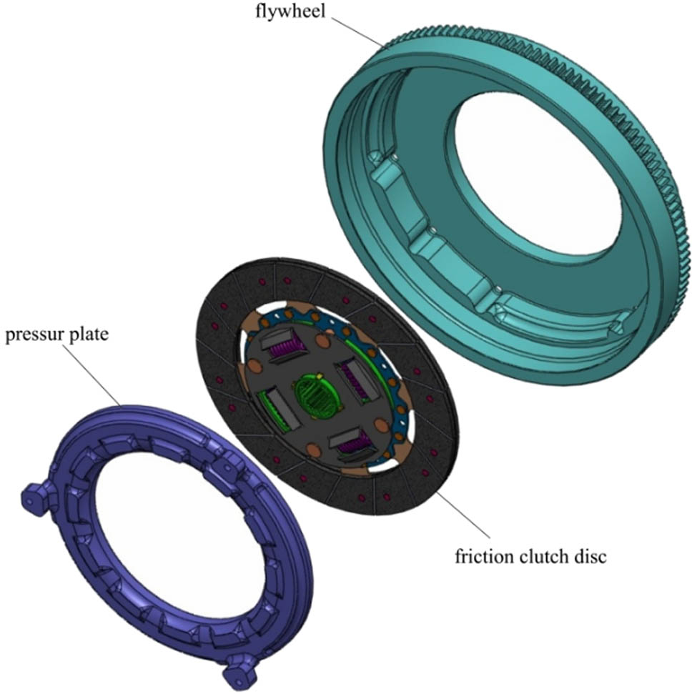
The main components of the clutch system.
In this work, first, a numerical model of the clutch system was established to obtain a thermal solution that would simulate the thermal problem during sliding time, which was used to make comparisons between the results of the normal model (layers) and the principle of equivalent properties. To determine whether the equivalent principle worked where functionally graded material (FGM) served as a friction lining. Secondarily, a mathematical model for the clutch system was used to overcome the heat problem that arose during the sliding period, which depends on how you apply the equivalence principle to FGM. The effects of many parameters, such as torque, variety of friction materials, slip time, and velocity, have been examined. The novelty in this work is the development of the analytical solution to make it applicable to FGMs by using the principle of equivalent properties.
2 The analytical model
2.1 Energy dissipation: A two-inertia system
In order to perform an analysis of the fundamental power transmission system depicted in Figure 2, the following assumptions must be met [25]:
It is assumed that torque T is always constant.
The friction coefficient remains constant.
Perfect rigidity is postulated for the system.
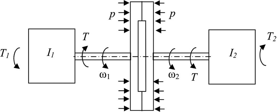
The basic system of power transmission.
The dynamical relationships are as follows:
The Boundary Conditions:
at side 1: at T = T 1,
at side 2: at T = T 2,
When these equations are integrated, and the boundary conditions are substituted, give;
Thus, the rate at which heat is generated per unit area of the friction surface during a single clutch engagement is given by
Figure 3 shows that the rate of energy loss during the sliding phase goes down in a straight line with time.
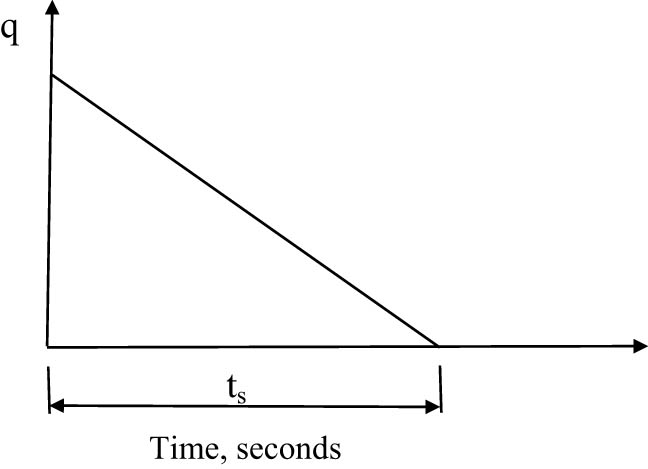
Behavior of heat flux per time during a clutch application.
By substituting Eq. (2) in Eq. (3) and equating with 4 obtain,
For a special case, at T 1 = T 2 = 0, when no external torques are acting on the system and it consists just of two inertias I 1 and I 2 rotating at different speeds [25],
2.2 The solution of the heat problem
Figure 4 shows a cross-section of a single-plate clutch operating under the influence of an axial clamping force P. The inner plate is made up of two friction plate materials riveted to thin spring steel segments. The two outer plates are made of steel and have various thicknesses, d 1 for the pressure plate and d 3 for the flywheel plate.
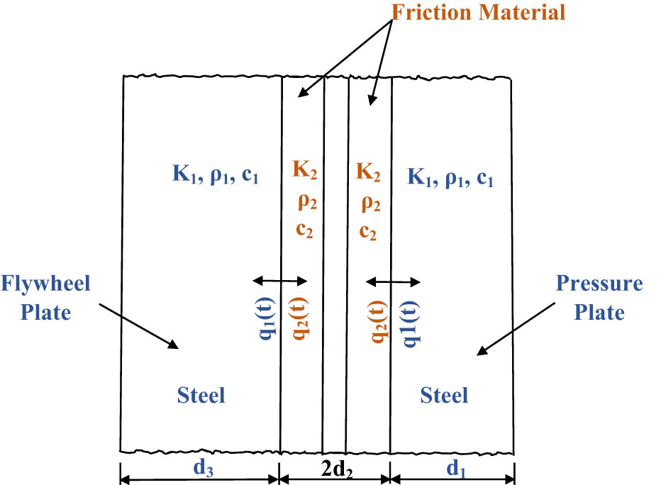
Diagrammatic sketch demonstrating the heat created at a single-plate friction clutch rubbing surfaces and its flow.
In this case, the rate of heat generation would be directly related to the tangential velocity and hence to the radial position on the plate surface, which would contradict the requirement that the pressure be uniform over the plate. The rate of energy loss at surfaces where rubbing occurs, in contrast, is solely a function of time. The rates of heat transfer between two surfaces in contact are not equal but rather dependent on their differing thermal characteristics [25].
Since only a small portion of the friction surface is heated during the slipping period (t s) in typical clutch applications, the contacting bodies can be thought of as having an infinite thickness in this scenario. Odier [26] and Hasselgruber [27] have thought about this heat conduction issue and have derived formulations for the growth in surface temperature that are as follows [25]:
3 The selected materials
The metal chosen for the investigation is Sic–Al, which is functionally graded in terms of thickness and comes in three layers. The interface’s first layer is made up of 57% aluminum and 43% silicon carbide, followed by a second layer that is made up of 19% silicon carbide and 81% aluminum, and a third layer that is entirely made up of aluminum (Table 1).
Displays all of the problem’s parameters
| Parameter | Value |
|---|---|
| Inner radius of clutch disc and axial cushion [m] | 0.06 |
| Outer radius clutch disc and axial cushion [m] | 0.09 |
| Frictional facing thickness [m] | 0.003 |
| Inner radius of the pressure plate | 0.064 |
| Outer radius of pressure plate [m] | 0.094 |
| Inner radius of flywheel [m] | 0.031 |
| Outer radius of the flywheel [m] | 0.125 |
| Pressure plate thickness d 1 [m] | 0.005 |
| Flywheel thickness of d 3 [m] | 0.01 |
| Coefficient of friction (μ) of material Sic and Al | 0.6, 0.47 |
| Angular sliding velocity (n) [rpm] | 5,300 |
| Density of materials: Sic and Al [kg m−3] | 3,100, 2,770 |
| Specific heat of materials: Sic and Al [J kg−1 K−1] | 750, 923.5 |
| Thermal conductivity of material Sic and Al [W m−1 K−1] | 120, 160 |
| Density [kg m−3], specific heat [J kg−1 K−1], and thermal conductivity [W m−1 K−1] of the flywheel, pressure plate, and axial cushion | 7,200, 400, 56 |
| Slipping time (t s) [s] | 0.4 |
| Torque [N m] | 126 |
| Initial temperature [K] | 300 |
4 Equivalent principle of FGM properties
Consider steady-state heat transfer in the context of a unit-length multi-structure design with n layers of varying thickness t i and any property λ i . Because the flux led via layers is similar in each layer of the discrete structure and should be similar in homogenized material, if it is first assumed the heat flow is one-dimensional and perpendicular to the layer direction, it can be written [28]:
The above equation is used to compute thermal conductivity, where λ sy is the effective characteristics of the FGM in the y direction, also known as the thickness direction. While employing thermal energy balance for specific heat [29],
where c T is the sample’s specific heat capacity, M is the sample’s mass, c 1,2,3,4 is the specific heat capacity of the appropriate layer, and m 1,2,3,4 is the sample’s mass of the respective layer. And density is calculated as follows [30]:
where ρ 1,2,3,4 is the density of each layer and n i is the total number of layers.
A used numerical model was examined to demonstrate the capability of the method for computing the effective properties offered (as per Eqs. (2)–(4)), where it used the model boundaries that were established in 2012 by Abdullah and Schlattmann [30]. The details of a model are illustrated in Figures 5 and 6, and the numerical technique steps (FE) to solve the transient thermal problem are depicted as a flowchart in Figure 7. Two FGM numerical models were compared, one of which was built using the standard method or, at the very least, is made up of several layers, and the other whose properties were determined by the equations. The results depicted in Figure 8 indicated very good agreement between the two models, confirming the validity of the suggested approach.
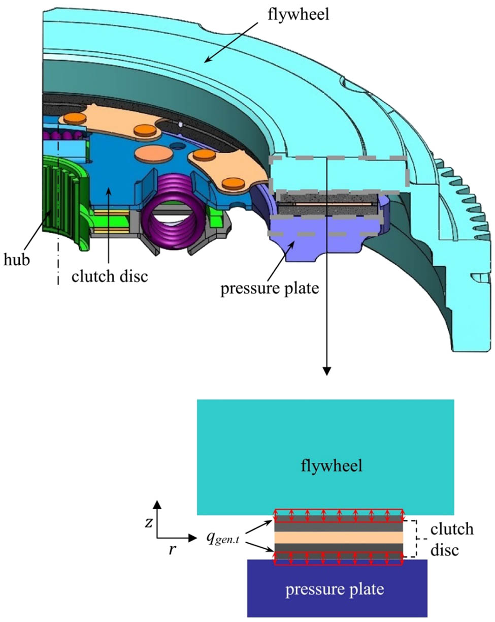
Axisymmetric model of a clutch system with boundary conditions.
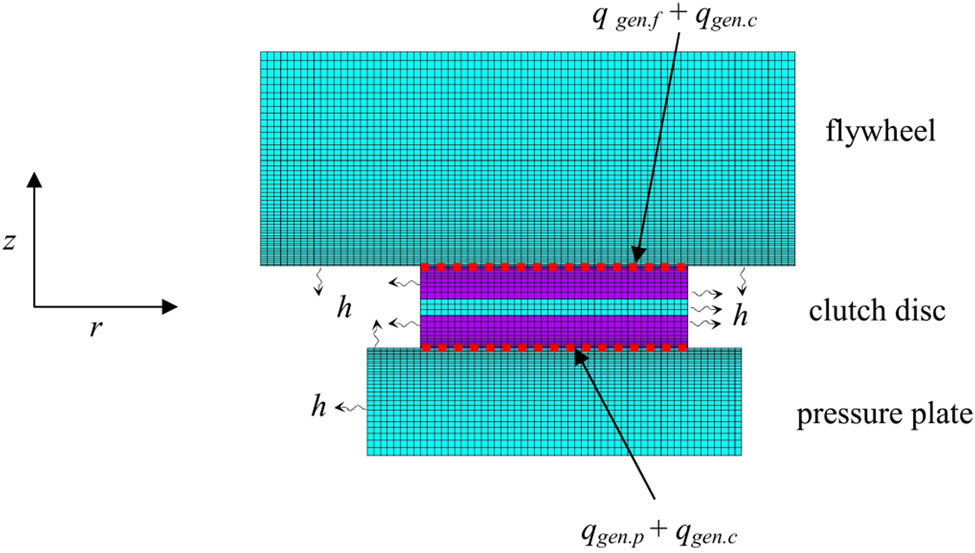
FE model with boundary conditions of a single-disc clutch system (no. of elements = 6,488).
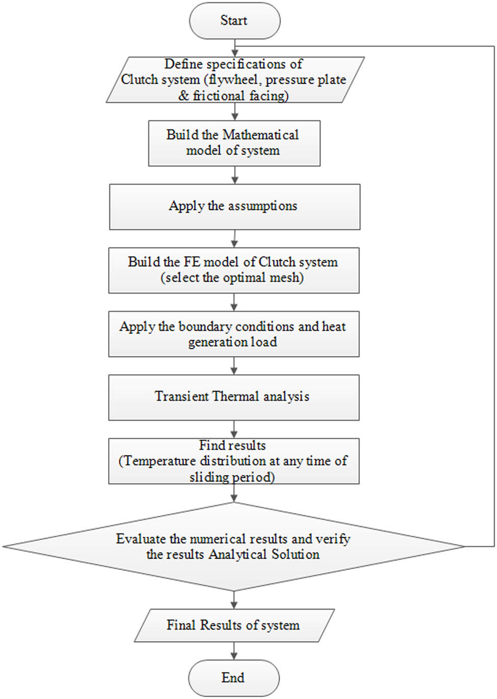
The flowchart of the developed numerical analysis using FEM.
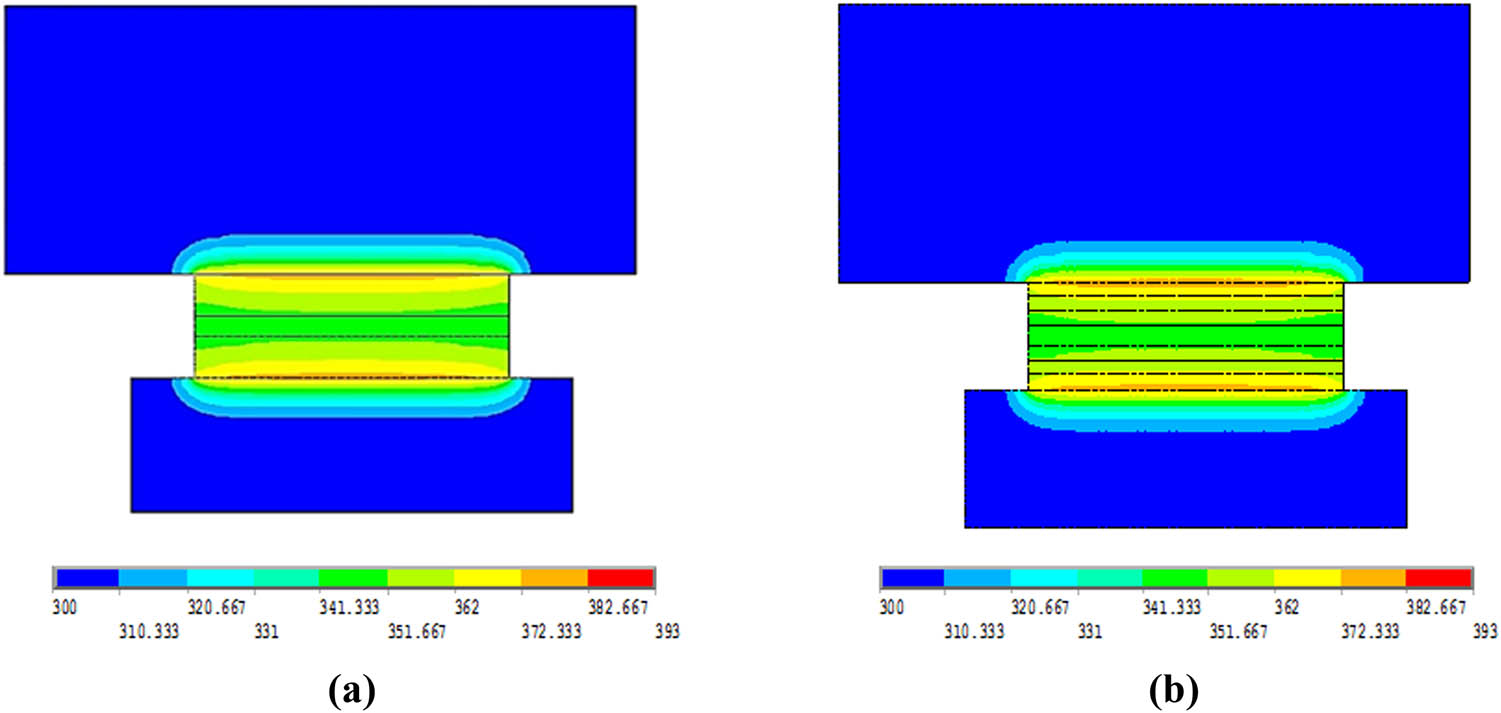
The numerical examination of equivalent properties approach (temperatures in Kelvin): (a) FGM_equivalent properties, (b) FGM_3 Layers.
5 Validation of the analytical processing
A validation test was carried out to make sure the produced solution was error-free. As shown in Figure 9, a comparison analytical model was run using only the numerical portion of Sabri et al.’s research [5]. Table 2 and Figure 7 show the data and boundary conditions used in the comparison. The largest inaccuracy discovered was 3.3310−4.
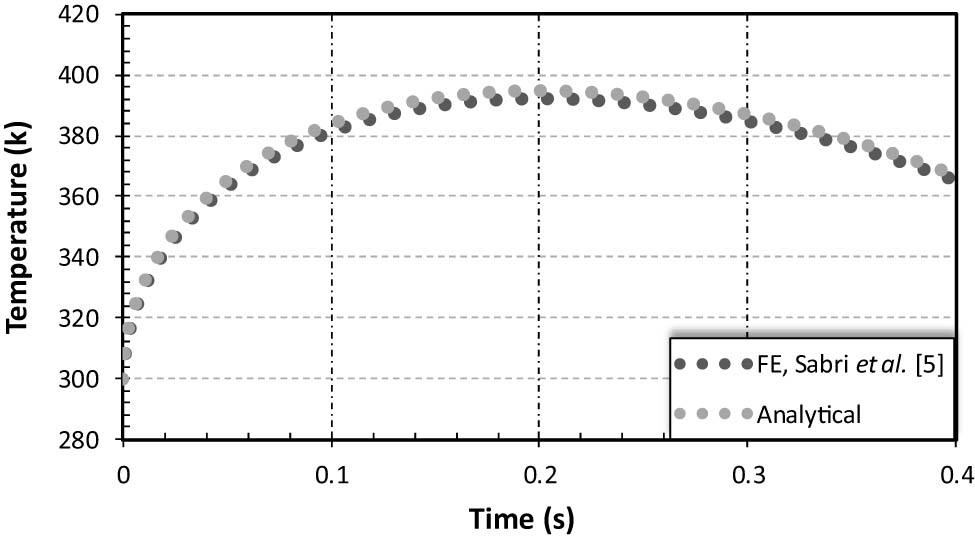
The comparison between the analytical and numerical solutions.
The important data about the working conditions and material used for comparison [5]
| Parameter | Value |
|---|---|
| Frictional facing thickness [m] | 0.004 |
| Angular sliding velocity (
|
295 |
| Density of friction material [kg m−3] | 1,000 |
| Specific heat of friction materials [J kg−1 K−1] | 1,000 |
| Thermal conductivity of friction material [W m−1 K−1] | 0.75 |
| Slipping time (t s) [s] | 0.4 |
| Applied pressure [MPa] | 1 |
| Initial temperature [K] | 300 |
6 Results and discussions
In order to obtain the range of temperatures under some parametric analysis, this study includes an analytical solution. The boundaries and factors without dimensions were displayed [31]:
In all figures, the vertical axis shows the relation between energy dissipation and energy generation, while the horizontal axis represents the total time to slip time.
6.1 Effect of the friction material on the clutch’s thermal behavior
The type of friction material used has a significant impact on the disc clutch case’s thermal and tribological conductivity. The type of friction material used has a significant impact on the disc clutch case’s thermal and tribological conductivity. This section examines the thermal behavior of three different disc clutch lining materials. Aluminum Al, FGM, and silicon carbide Sic were used as the materials. Figure 10 shows that the temperature of the Sic–Al liner during the sliding phase is significantly lower than that of the other two Sic and alumina lining types. The Sic–Al liner is the best option from a thermal perspective.
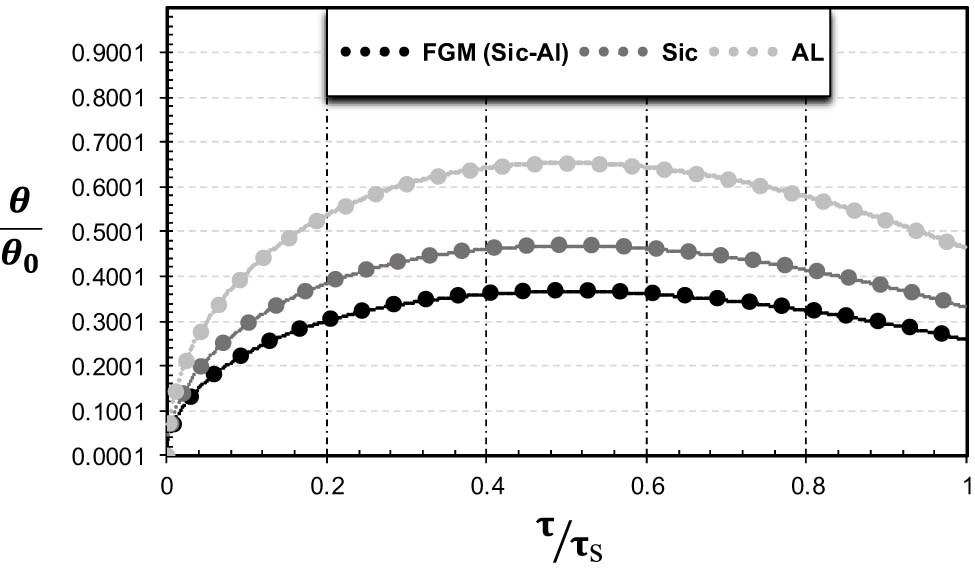
Temperature distribution at the dry clutch’s component interfaces for various materials when the torque is 126 Nm, and the speed is 5,300 rpm.
6.2 Influence of the speed of rotation
The friction torque and thermal streams entering and subsequently affecting the thermal behavior of the clutch plate are impacted by the rotating speed. Figure 11 depicts the progression of the maximum clutch plate temperature as a function of slip time at various speed rates. The dimensionless figure shows that the rate of dissipation to generation energy is constant for varying velocity values at constant torque and slip time.
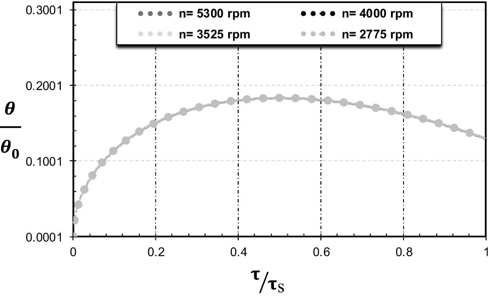
Temperature distribution at the dry clutch’s component interface for various speeds, torque of 126 Nm, and slip time of 0.4 s.
6.3 Effect of loads on the disc temperature
Figure 12 depicts how applying pressure to the clutch full plate’s two contact faces affects how the clutch behaves thermally as a function of the slip time. The magnitudes of the chosen pressure for the study were (1, 0.5, 0.125, and 0.62) MPa [12]. The clutch plate’s temperature increases in direct proportion to the amount of stress it is under. This happens as a result of the incoming heat stream being directly affected by the pressure being applied to the plate. When other factors are constant, the dimensionless structure responds to changing pressure values in the same form, where it is under constant effect with dimensionless time.
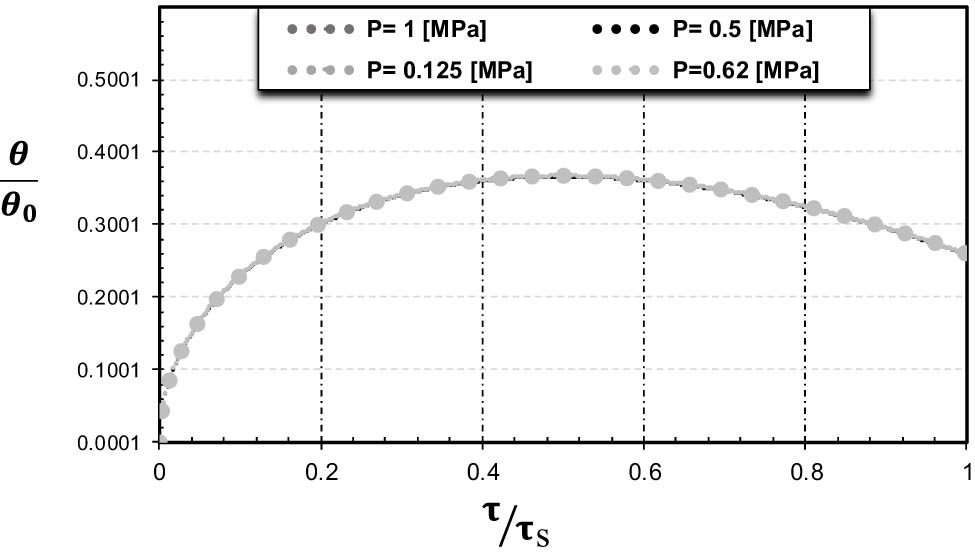
Temperature distribution at the dry clutch’s component interface for various loads at 5,300 rpm and 0.4 s of slip.
6.4 Effect of sliding time on the disc temperature
Figure 13 depicts the analytical results of temperature fluctuations in the contacting surfaces during various slipping periods. The magnitudes of the study’s chosen slip time were 0.25, 7.75, and 12.75 s [30]. The curves that address the thermal pattern of behavior of the clutch system can be seen to have a few important points. First and foremost,
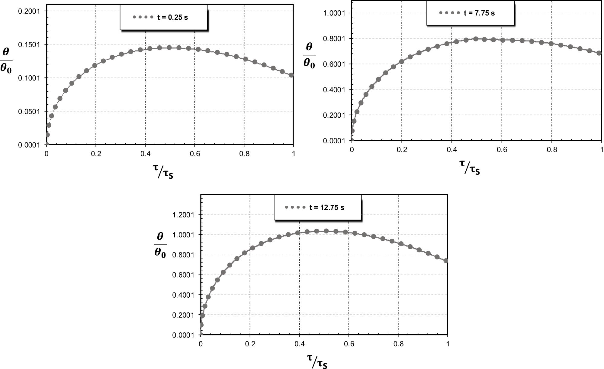
Temperature distribution at the dry clutch’s component interface for various slip periods, with a velocity of 5,300 rpm and a constant torque of 126 Nm.
The quantity of heat generated is a function of time, beginning at zero at the beginning of the slip, increasing until it reaches its greatest value at the halfway point, and then decreasing from its most extreme value to zero as the clutch is fully engaged. variety through the engagement duration, and sliding velocity. This is due to the start of the engaging stage, after with contacts. Numerous characteristics, including torque variation across the engagement length and sliding velocity, were affected by the temperatures that were produced during the sliding period. This is because after the clutch and flywheel make contact, the torque of the transmission begins to steadily increase. Transmission torque is now lower than motor torque because it is insufficient to overcome the negative torque generated by the wheels [32]. At the halfway point of the engagement stage, the vehicle starts to move, the clutch velocity closes in on the motor velocity, and the transmitted torque overcomes the negative torque. As a result of the increased speed and torque, a greater load will be required to overcome the beginning or negative rates, which causes the rate of heat generation to increase at a noticeably faster rate.
7 Conclusions and remarks
The transient temperature field in a friction material, in which a pad is constructed of a FGM, was calculated using a mathematical model. It was anticipated that as one moved away from the contact surface, an FGM’s thermal conductivity would grow exponentially. For the FGM (Sic + Al), a numerical study was done to compare the normal and equivalent characteristics. Following the applications of the dimensionality formula to the results, it was discovered that some parameters, such as velocity and load, exhibited the same behavior regarding the relationship between temperature and time, indicating that the rate of heat generation and dissipation is constant independent of changes in the parameter values. The sliding time and the variety of friction materials showed a difference in thermal behavior with time because the generation of heat is subject to different characteristics in each case, which indicates the great importance of these two factors on the heat generated and then on the work efficiency and life of the clutch system. The FGM also demonstrated that, when compared to the other materials of which it is composed, it has good thermal behavior, increasing the likelihood that it can be used in this application. On the other hand, the work system necessitates good mechanical properties, which these kinds of materials have.
-
Funding information: Authors state no funding involved.
-
Author contributions: All authors have accepted responsibility for the entire content of this manuscript and consented to its submission to the journal, reviewed all the results and approved the final version of the manuscript. Methodology, investigation, writing – review and editing, resources: NAJ & IYH; validation, funding acquisition, resources, writing – review and editing: MJJ & HSSA; formal analysis, funding acquisition, resources, conceptualization, and supervision: MNM & OIA.
-
Conflict of interest: Authors state no conflict of interest.
-
Data availability statement: The study did not report any data.
References
[1] Al-Zubaidi S, Senatore A, Abdullah OI, Scuotto N. Effect of sliding speed on the thermal fields and frictional behaviours of asbestos-free frictional materials used for dry clutch system. In IOP Conference Series: Materials Science and Engineering. Vol. 881, Issue 1, IOP Publishing; 2020, July. p. 012086.10.1088/1757-899X/881/1/012086Search in Google Scholar
[2] Wang H, Wang B, Pi D, Wang E, Wang X. Two-layer structure control of an automatic mechanical transmission clutch during hill start for heavy-duty vehicles. IEEE Access. 2020;8:49617–28.10.1109/ACCESS.2020.2979901Search in Google Scholar
[3] Della Gatta A, Iannelli L, Pisaturo M, Senatore A, Vasca F. A survey on modeling and engagement control for automotive dry clutch. Mechatronics. 2018;55:63–75.10.1016/j.mechatronics.2018.08.002Search in Google Scholar
[4] Jabbar NA, Hussain IY, Abdullah OI. Thermal and thermoelastic problems in dry friction clutch: A comprehensive review. Heat Transf. 2021;50:7855–78.10.1002/htj.22257Search in Google Scholar
[5] Sabri LA, Topczewska K, Jweeg MJ, Abdullah OI, Abed AM. Analytical and numerical solutions for the thermal problem in a friction clutch system. Computation. 2021;9:122.10.3390/computation9110122Search in Google Scholar
[6] Al-Shabibi AM. Transient behavior of initial perturbation in multidisk clutch system. Tribol Trans. 2014;57:1164–71.10.1080/10402004.2014.945198Search in Google Scholar
[7] Al-Shabibi AM. Solution of heat conduction problem in automotive clutch and brake systems. Heat Transf Summer Conf. 2008;48470:321–6.10.1115/HT2008-56467Search in Google Scholar
[8] Xiong C, Chen M, Yu L. Analytical model and material equivalent methods for steady state heat partition coefficient between two contact discs in multi-disc clutch. Automob Eng. 2019;234:857–71.10.1177/0954407019846389Search in Google Scholar
[9] Al-Shabibi AM, Barber JR. Transient solution of the unperturbed thermoelastic contact problem. J Therm Stresses. 2009;32:226–43.10.1080/01495730802507980Search in Google Scholar
[10] Fatin EG. Thermal modeling and simulation of dry friction clutches in heavy duty trucks. M.Sc. thesis. Istanbul Technical University; 2015.Search in Google Scholar
[11] Kılıç M, Çakmak T, Sevilgen G. Clutch pressure plat compactness effect on the clutch system heat dissipation. 12th International Conference on Heat Transfer, Fluid Mechanics and Thermodynamics; 2016.Search in Google Scholar
[12] Mouffak E, Bouchetara M. Transient thermal behavior of automotive dry clutch discs by using Ansys software. Mechanika. 2016;22(6):562–70.10.5755/j01.mech.22.6.17277Search in Google Scholar
[13] Pica G, Cervone C, Senatore A, Lupo M, Vasca F. Dry dual clutch torque model with temperature and slip speed effects. Intell Ind Syst. 2016;2:133–47.10.1007/s40903-016-0049-6Search in Google Scholar
[14] Abdullah OI, Schlattmanna J. Thermoelastic analysis of grooved friction clutches using finite element method. Tribol Trans. 2017;60(6):1011–102.10.1080/10402004.2016.1243284Search in Google Scholar
[15] Jenan SS, Ihsan YH, Abdullah OI. Finite element simulation of thermal behavior of dry friction clutch system during the slipping period, Ph.D, Baghdad University, College of Engineering, mechanical Department; 2019.Search in Google Scholar
[16] Çakmak T, Kılıç M. Clutch transient heat transfer simulation for hill start vehicle test condition. 13th International Conference on Heat Transfer, Fluid Mechanics and Thermodynamics; 2017.Search in Google Scholar
[17] Liu H, Lee JC, Noh YJ, Cho JH, Lee HR, Koh JE, et al. A study on thermal analytical model for a dry dual-clutch. J Drive Control. 2015;12(1):1–8.10.7839/ksfc.2015.12.1.001Search in Google Scholar
[18] Abdullah OI, Schlattmann J. Thermal behavior of friction clutch disc based on uniform pressure and uniform wear assumptions. Friction. 2016;4(3):228–37.10.1007/s40544-016-0120-zSearch in Google Scholar
[19] Gkinis T, Rahman R, Rahnejat H, Martin O. Heat generation and transfer in automotive dry clutch engagement. J Zhejiang Univ-Sci A (Appl Phys Eng). 2018;19(3):175–88.10.1631/jzus.A1700481Search in Google Scholar
[20] Ye K, Liu Q, Gao B, Chen H. Thermal-friction modeling and analysis for automotive dry clutch systems. Proceedings of the 35th Chinese Control Conference; 2016.10.1109/ChiCC.2016.7553702Search in Google Scholar
[21] Sherza JS, Hussain IY, Abdullah OI. Heat flux in friction clutch with time dependent torque and angular velocity. In 2018 International Conference on Advanced Science and Engineering (ICOASE). IEEE; 2018, October. p. 474–8.10.1109/ICOASE.2018.8548879Search in Google Scholar
[22] Akgöz B, Civalek Ö. Effects of thermal and shear deformation on vibration response of functionally graded thick composite microbeams. Compos Part B: Eng. 2017;129:77–87.10.1016/j.compositesb.2017.07.024Search in Google Scholar
[23] Brischetto S, Torre R. 3D shell model for the thermo-mechanical analysis of FGM structures via imposed and calculated temperature profiles. Aerosp Sci Technol. 2019;85:125–49.10.1016/j.ast.2018.12.011Search in Google Scholar
[24] Tornabene F, Viscoti M, Dimitri R. Thermo-mechanical analysis of laminated doubly-curved shells: Higher order equivalent layer-wise formulation. Compos Struct. 2024;335:117995.10.1016/j.compstruct.2024.117995Search in Google Scholar
[25] Newcomb TP. Temperatures reached in friction clutch transmissions. J Mech Eng Sci. 1960;2(4):273–87.10.1243/JMES_JOUR_1960_002_037_02Search in Google Scholar
[26] Odier JCR. Contribution to the study of the influence of temperature on braking problems. Paris: C.R. Academic Science; 1954. p. 1288.Search in Google Scholar
[27] Hasselgruber H. Temperature calculations for mechanical friction clutches. Braunschweig, German: Vieweg und Sohn; 1959. p. 16.Search in Google Scholar
[28] Turant J, Radaszewska E. Thermal properties of functionally graded fibre material. Fibres Text East Europe. 2016;4(118):68–73.10.5604/12303666.1201133Search in Google Scholar
[29] Rong KF. Study and development of novel composite materials for the application of car brake rotor. M.sc. thesis. Australia: Curtin University; 2014.Search in Google Scholar
[30] Abdullah OI, Schlattmann J. Finite element analysis of temperature field in automotive dry friction clutch. Tribol Ind. 2012;34(4):206–2016.Search in Google Scholar
[31] Yevtushenko A, Kuciej M, Topczewska K, Zamojski P. Temperature in the friction couple consisting of functionally graded and homogeneous materials. Materials. 2022;15(10):3600.10.3390/ma15103600Search in Google Scholar PubMed PubMed Central
[32] Faidh-Allah MH. The temperature distribution in friction clutch disc under successive engagements. Tribol Ind. 2018;40(1):92–9.10.24874/ti.2018.40.01.08Search in Google Scholar
© 2024 the author(s), published by De Gruyter
This work is licensed under the Creative Commons Attribution 4.0 International License.
Articles in the same Issue
- Research Articles
- Flutter investigation and deep learning prediction of FG composite wing reinforced with carbon nanotube
- Experimental and numerical investigation of nanomaterial-based structural composite
- Optimisation of material composition in functionally graded plates for thermal stress relaxation using statistical design support system
- Tensile assessment of woven CFRP using finite element method: A benchmarking and preliminary study for thin-walled structure application
- Reliability and sensitivity assessment of laminated composite plates with high-dimensional uncertainty variables using active learning-based ensemble metamodels
- Performances of the sandwich panel structures under fire accident due to hydrogen leaks: Consideration of structural design and environment factor using FE analysis
- Recycling harmful plastic waste to produce a fiber equivalent to carbon fiber reinforced polymer for reinforcement and rehabilitation of structural members
- Effect of seed husk waste powder on the PLA medical thread properties fabricated via 3D printer
- Finite element analysis of the thermal and thermo-mechanical coupling problems in the dry friction clutches using functionally graded material
- Strength assessment of fiberglass layer configurations in FRP ship materials from yard practices using a statistical approach
- An enhanced analytical and numerical thermal model of frictional clutch system using functionally graded materials
- Using collocation with radial basis functions in a pseudospectral framework to the analysis of laminated plates by the Reissner’s mixed variational theorem
- A new finite element formulation for the lateral torsional buckling analyses of orthotropic FRP-externally bonded steel beams
- Effect of random variation in input parameter on cracked orthotropic plate using extended isogeometric analysis (XIGA) under thermomechanical loading
- Assessment of a new higher-order shear and normal deformation theory for the static response of functionally graded shallow shells
- Nonlinear poro thermal vibration and parametric excitation in a magneto-elastic embedded nanobeam using homotopy perturbation technique
- Finite-element investigations on the influence of material selection and geometrical parameters on dental implant performance
- Study on resistance performance of hexagonal hull form with variation of angle of attack, deadrise, and stern for flat-sided catamaran vessel
- Evaluation of double-bottom structure performance under fire accident using nonlinear finite element approach
- Behavior of TE and TM propagation modes in nanomaterial graphene using asymmetric slab waveguide
- FEM for improvement of damage prediction of airfield flexible pavements on soft and stiff subgrade under various heavy load configurations of landing gear of new generation aircraft
- Review Article
- Deterioration and imperfection of the ship structural components and its effects on the structural integrity: A review
- Erratum
- Erratum to “Performances of the sandwich panel structures under fire accident due to hydrogen leaks: Consideration of structural design and environment factor using FE analysis”
- Special Issue: The 2nd Thematic Symposium - Integrity of Mechanical Structure and Material - Part II
- Structural assessment of 40 ft mini LNG ISO tank: Effect of structural frame design on the strength performance
- Experimental and numerical investigations of multi-layered ship engine room bulkhead insulation thermal performance under fire conditions
- Investigating the influence of plate geometry and detonation variations on structural responses under explosion loading: A nonlinear finite-element analysis with sensitivity analysis