Finite-element investigations on the influence of material selection and geometrical parameters on dental implant performance
-
Ahmed Ali Farhan Ogaili
 ,
Qasim Saleh Mahdi
,
Qasim Saleh Mahdi

Abstract
Dental implants provide functional and aesthetically pleasing dental replacements, but their longevity depends on biomechanical factors, physical characteristics, and patient variability. The present study used finite-element analysis to reveal the biomechanical response and potential modes of failure of dental implant systems subjected to normal occlusal loads. A generalized comparative assessment was carried out to measure the effect of the choice of crown material with zirconia, porcelain-fused-to-metal, and ceramic crowns. Such simulations showed complex patterns of stress distribution and deformation in the implant assembly with significant variation due to the mechanical properties of the crown material. Stiffer zirconia crowns magnified stress concentrations by 12.6, 10.8, 11.4, and 9.1% in the implant fixture, crown, cortical bone, and cancellous bone, respectively, compared with more compliant ceramic crowns. Furthermore, the maximal deformation of both the cortical and cancellous bone induced by zirconia crowns was higher by 21.1 and 19.2%, respectively, compared with the ceramic crowns. These results emphasize that the crown material properties are significant for controlling and modulation biomechanical load transfer, which plays a decisive role in the long-term durability and resistance to failure mechanisms such as interfacial debonding, bone resorption, and fatigue cracking. This study provides valuable information for optimizing implant designs and material selection that may improve clinical results, positively affecting patient satisfaction with dental implant therapy.
1 Introduction
Dental implants technology has led to a major qualitative leap in the field of restorative dentistry, as it is no longer just a restoration of teeth, but rather a natural implantation of teeth through a careful combination of tissues and jaw bone compound [1]. Dental implants have many advantages in addition to aesthetics; they give lasting durability [2]. However, the mechanism of its lifespan remains linked to its harmony with multifaceted biomechanical forces, as well as patient-specific factors that require careful study [2,3].
For the purpose of analyzing the distribution patterns of compound stresses generated in dental implants, it has become necessary to use finite-element analysis (FEA) software to predict the magnitude of the delay in many cases [4].
Dental implants are the process of replacing missing teeth with implants that are surgically inserted into the jawbone, and these implants are brilliantly made of titanium and other biocompatible materials [5]. These implants are used for the fixation of artificial teeth and crown restoration work, and they distinctively mimic the appearance and function of natural teeth. The widespread adoption of dental implants is increasing with impressive success rates and its unparalleled ability to improve function and aesthetics [6]. Unlike the harmful bone loss that accompanies missing teeth is caused by alternative tooth operations such as bridges and dentures, implants actively stimulate bone growth [7]. The implant fuses with the bone through bone fusion, resulting in a strong and stable foundation that makes the method of fitting the artificial tooth safe [8]. In the long run, there are many factors that affect the success of dental implants in many ways, including the quality and quantity of jawbone, implant surgery, implant materials, inherent biocompatibility, influencing forces such as dish size and trends, and permanent maintenance of oral hygiene [8]. The critical interaction between these components ultimately determines the flexibility and durability of implants.
2 Literature review
Many studies have delved into the analysis of complex biomechanical factors that have an influential role in the durability and efficiency of dental implants. Each study contributed to the understanding of this complex issue. A common failure is the cracking of implants or components, which leads to a set of expected failure mechanisms [3]. Wide research has shown that the value and direction of the occlusal forces during the seemingly harmless chewing and biting process can accelerate mechanical stress on implants, culminating in bone loss over time [9,10]. FEA-specific analysis programs are highly valuable in modeling and analyzing the stresses overlaid in the bone structure surrounding dental implant. FEA software is highly valuable in modeling and analyzing the stresses overlaid in the bone structure surrounding dental implants [11–13]. There is a wealth of investigations that have investigated the effect of different parameters on dental implants in the specific element analysis literature, including prosthesis type, bone quality, surface design, and implant geometry, on the resulting stress distributions [10,13,14]. As a result of frequent research and advances in analysis, a deeper understanding of implant behavior is generated. Remarkable advances in the methodology of recent studies include detailed models of three-dimensional implants, time-dependent loading regimes, and nonlinear contact interactions. These advances have improved the understanding and prediction of bone remodeling phenomena and implant failure modes with higher accuracy [8,15].
As a result, FEA techniques promise a new era, where a seamless interconnection has been established between biomechanical simulation and performance optimization algorithms to determine the optimal implant location and design [5,16,17]. Recent studies have harnessed the power of FEA to evaluate the intricate biomechanical effects of platform-switching on stress distribution [18], micro-motion on bone–implant interfacial strains, and fatigue failure risks of implant–abutment connections (IAC) [16]. Other analyses that emerged in the field of probabilistic FEAs included variable material properties and random occlusion loads to better account for variation in clinical scenarios [16,19,20].
In this study, we explore the interaction between various materials and biomechanical stresses to enhance the sustainability of dental implant designs. This research transcends traditional boundaries in implant studies by offering a comprehensive perspective that aligns with the clinical demands of dental care. The findings could significantly influence clinical practices by providing a thorough understanding of how stresses are applied and the potential failure mechanisms of dental implants. This investigation lays a scientific foundation for making informed decisions about implant material selection and design modifications, thereby making a substantial contribution to the field of dental implants. Ultimately, this research aims to improve patient satisfaction and care.
The structure of this article is as follows: Section 2 reviews the literature on biomechanical factors affecting dental implant longevity and the role of FEA. Section 3 describes the materials and methods, detailing the finite-element model used. Section 4 presents and discusses the results of our simulations, comparing these with existing research. Finally, Section 5 concludes the article by summarizing key findings and suggesting avenues for future research.
3 Materials and methods
The following section delineates the methodological approach employed in this study. We provide a detailed description of the finite-element model construction, including geometrical considerations, material property assignments, and boundary condition specifications. The rationale behind our choices is explained, ensuring transparency and reproducibility of our research.
3.1 Geometrical model
Geometric models of implants were created using SolidWorks 2021, which was chosen for its sophisticated functionality in modeling intricate details, dimensions, and precision. When crowns, implants, and masts are formed to clinical standards, it can assure that simulations will accurately reflect the situation that arises in the real world. Figure 1 illustrates radiographic images showing the placement and integration of dental implants in the anterior maxilla.

Radiographic images showing the placement and integration of dental implants in the anterior maxilla.
3.1.1 Crown geometry
The crown geometry model closely followed the shape of the maxillary central incisor, as described in the related literature [15]. Great importance was placed on the reconstruction of important anatomical features such as a curved labial surface, an incised edge [21], and an asymmetric lingual surface, as shown in Figure 2. In addition, body load models were used to develop a method for whip stress distribution along the occlusal table and cusp inclines.

Geometrical model of the crown showing the detailed anatomical features used in the FEA.
3.1.2 Implant fixture geometry
The dimensions of the titanium implant fixture, which had a trapezoidal thread pattern and a tapered body, were verified by comparing them to the dimensions of implants available on the market. The thread depth and pitch were carefully chosen according to standard procedures. The object was to enhance the initial stability and make it better for loads to be spread out at the important point where the bone meets the implant [22].
3.1.3 Mandibular bone geometry
It has been developed considering both the cortical and cancellous structures in a highly accurate mandibular bone model [23]. The dual-layer methodology was essential for appropriate investigations of stress transfer and potential bone remodeling phenomena. For this reason, the accuracy level and practicality of the simulations in a clinical framework were substantially enhanced. The mandibular bone model was constructed using extruded geometry. That technique was utilized to allow the complex anatomy to be simplified yet, at the same time, to keep the central biomechanical features that are relevant to our studies. The extruded geometry allowed for a computational analysis to be done more efficiently, at the expense of much of the accuracy of the stress and strain distributions in the areas of interest surrounding the implant. This simplification is particularly useful in focusing the analysis on the immediate vicinity of the implant, where the critical stress interactions are taking place. The components were modeled in SolidWorks 2021, and the dimensions were found according to values stipulated in agreements with references such as [24]. The geometries were cross-verified with clinical measurements. The employment of the two-stage approach is depicted in Figure 2, which is vital in establishing the correct evaluation of the stress transfer and probability of bone reconstruction. This permitted clinical relevance and improved the effectiveness of the simulations. Physiological data of the extent close to the memorized geometric properties and measurements were considered from the scientific literature to reproduce the accuracy [25].
3.2 Modeling process
The modeling approach used in this study followed a series of carefully strategic and rigorous steps to ensure accurate and faithful representation of implants has simulated their biomechanical behavior. This comprehensive approach involved modeling the crown, implant fixture, and mandibular bone as individual components within the SolidWorks 2021 computer-aided design (CAD) environment. Each component was carefully constructed to ensure accurate representation of the dental implant system. The geometry of the crown was carefully designed, each aspect and thickness being accurately modeled to mimic the complex anatomy of the maxillary central incisor, the convexity of the labial surface and the intricate shape of the incisal tip. The implant fixture geometry was similarly modeled with a careful focus on detail. The tapered body and trapezoidal thread shape were rigorously validated against commercial implant specifications, ensuring dimensional accuracy. Also, the depth and tone of the threads were designed in strict compliance with established guidelines, with the explicit goal of optimizing the stability of the first layer to provide optimal load carriage elsewhere at the critical interface between bone and implant is weakened [18]. The mandibular bone model was constructed with equal diligence, incorporating accurate representations of both the cortical and cancellous structures.
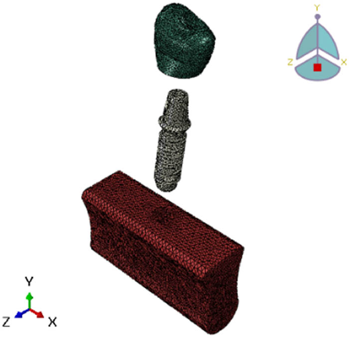
The adoption of this two-pronged approach was thus crucial in permitting a comprehensive investigation of stress transfer and possible phenomena of bone regeneration, hence the greater predictive capacity and clinical relevance of the simulations. The geometry and anatomy of the jawbone have been modeled with meticulous details, as per data gathered in the relevant scientific literature [25]. The model of the jawbone has been attentively created, to be able to describe realistically the cortical-cancellous structures. This required a two-stage methodology, as shown in Figure 3, for a complete evaluation of the tension transfer and potential difficulties that could arise during the prediction of bone resorption. These enhancements also enriched the predictability, accuracy, and clinical validity of the simulations. The geometric properties and dimensions of the neck were re-evaluated by using anatomical data taken from the scientific literature [26].

Assembly of the parts in the modeling process, including the crown, implant fixture, and mandibular bone.
Boundary conditions were applied in an attempt to simulate physiological constraints experienced in vivo. More specifically, they provided constraints to nodal displacements due to the mandibular bone model, replicated complex fixation seen in clinical scenarios, and ended at the powerful computing abilities of this application: characterized by biomechanical properties. The standards set by industry are strictly adhered to; the computer system analysis being in-depth, with such meager resources, really brings the robustness and reliability of the results of this study to the fore.
3.3 Contact theory implementation
The modeling process started in multisteps first by creating the crown, implant fixture, and mandibular bone components in SolidWorks 2021. These components were then assembled together in a comprehensive model representing the implanted state. Contact interactions and boundary conditions were applied to the assembly model in Abaqus finite-element software. The complete model was used to simulate the biomechanical behavior under masticatory loading. The accuracy of the representation of the interaction between the implant and the surrounding bone is critical to the capture of all complex biomechanical phenomena in this critical interference.
3.3.1 Numerical implementation and contact theory
In this study, a comprehensive finite-element model was implemented to simulate the interactions within the dental implant system using advanced contact mechanics. The model was developed and analyzed using Abaqus, a highly capable finite-element analysis software known for handling complex biomechanical simulations.
The critical interfaces, including the bone–implant interface and the implant–abutment connection, were modeled using frictional contact elements based on the Coulomb friction model. This approach realistically represents mechanical behaviors at these interfaces, such as micromotion and stress transfer [24]. In this analysis, the value of coefficient friction (μ) 0.3 was applied, as reported in values previously from the literature [27,28], based on experimental data for titanium implants in osseointegrated conditions [24]. This coefficient simulates relative motion between implant and bone surfaces, reflecting clinical conditions. For the IAC, a bonded contact condition was implemented to represent the tight fit typically achieved in clinical scenarios. The parameters included: The contact model was validated by comparing interfacial micromotion and stress distribution patterns with experimental data. The validation confirms the model’s reliability in replicating observed physical behaviors in clinical scenarios [29]. This rigorous implementation of contact theory, along with careful mesh refinement and validation, ensures accurate capture of complex biomechanical interactions within the dental implant system. This approach aligns with established methodologies in the field and incorporates specific refinements tailored to our research objectives.
3.4 Material properties
When modeling finite elements, the accuracy of the representation of processes and interactions is very important, as these factors have a great impact on the accuracy and prediction efficiency of the simulation process.
3.4.1 Crown and implant materials
The components of the crown are designed as a homogeneous zirconia structure, appearing homogeneous with isotropic properties. The modulus of elasticity and Poisson’s ratio of zirconia were used from the previous literature, and it was confirmed that the simulated deformation and stress response of the crown accurately reflected the behavior of this advanced ceramic material. In the same way, implant formulations are designed as homogeneous and isotropic titanium alloys using the properties mentioned in [13]. Titanium alloys are commonly used in dental implants for their biocompatibility, corrosion resistance, and mechanical resistance, which makes their representation in the finite-element model imperative. For the purpose of achieving a complete bone fusion simulation, which is the advantage of successful implant procedures, the crown interface and implant are designed as a tied connection. This method eliminates the relative movement between the components of the crown and the implant and thus ensures that the simulated stress and deformation patterns reliably replicate the biomechanical behavior of the integrated implant system.
3.4.2 Material properties
The accuracy and credibility of including the properties of bone material in this work were of high importance, as the mechanical behavior of the surrounding bone affects the stress distribution and potential failure mechanism of the implant system. The cortical bone is designed as an orthotropic material, capturing the direction-dependent modulus of elasticity and the Poisson’s ratio that characterizes the anisotropy properties.
For the orthotropic cortical bone model, the material reference system was oriented to align with the anatomical directions of the mandible. The x-axis was defined as the buccolingual direction, the y-axis as the mesiodistal direction, and the z-axis as the inferosuperior direction. This orientation ensures that the directional properties of the cortical bone are accurately represented in the model, capturing the anisotropic nature of bone tissue in relation to the physiological loading directions typically experienced in the mandible [30].
The properties were obtained from experimental data [31] so that the computer simulation of cortical bone could accurately reflect its mechanical behavior under physiological load conditions. This was done because the trabecular bone was designed as an isotropic material with a lower modulus of elasticity. Hence, it has a porous and less dense microstructure. The features were carefully chosen from the source [34] to correctly replicate load transfer and deformation within this essential part of the mandible (Table 1).
Material properties and references
| Component | Material | Properties | Ref. |
|---|---|---|---|
| Crown | Zirconia | Elastic modulus: 210 GPa, Poisson’s ratio: 0.3 | [32] |
| Ceramics | Elastic modulus: 100 GPa, Poisson’s ratio: 0.2 | [33] | |
| Porcelain-fused-to-metal (PFM) | Elastic modulus: 120 GPa, Poisson’s ratio: 0.28 | [33] | |
| Implant fixture | Titanium alloy | Elastic modulus: 110 GPa, Poisson’s ratio: 0.35 | [34] |
| cortical bone | Orthotropic | Ex = 12.6 GPa, Ey = Ez, νxy = 0.3, νyz = νxz | [32] |
| Cancellous bone | Isotropic | Elastic modulus: 1.37 GPa, Poisson’s ratio: 0.3 | [32] |
Incidentally, according to Sakka and Coulthard’s work [32], orthotropic nature is directionally dependent on elastic moduli and Poisson’s ratios in bone. Cancellous or trabecular bone was considered isotropic since it is pervious than more compact microstructure. These properties are derived from simulation results presented in [35], which are used for modeling crowns made of zirconia and implants fabricated from titanium, respectively. Analysis of finite elements was carried out to obtain elastic moduli and Poisson’s ratios for them [33]. The materials used to model zirconia crowns and titanium implants were isotropic and static, respectively, with their elastic moduli and Poisson’s ratios obtained through FEA [36]. For many decades now, porcelain-fused-to-metal (PFM) crowns have been very widely used as restorative materials in dentistry for several reasons. It is the most common material used in dentistry due to its combination of aesthetic properties with mechanical strength and wide use over several decades [36]. PFM can be considered one of the most suitable dental restorative materials. Several retrospective clinical studies have demonstrated satisfactory clinical outcomes using PFM restorations, which is mainly attributed to their combination of aesthetic properties and mechanical strength. These are metal substructures, usually of high noble or base metal alloy, veneered with a layer of feldspathic porcelain [26]. The metal substructure in PFM crowns will ensure adequate strength and rigidity to withstand masticatory loads, and the porcelain veneering layer will accommodate a lifelike appearance with better biocompatibility than a metal surface [37]. The bond between the metal and porcelain results from both mechanical interlocking and chemical bonding owing to the application of opaque porcelain layers during the fabrication process [37]. PFM crowns exhibited good mechanical properties; tensile strength was reported to be within a range of 300–600 MPa, while compressive strength was around 600 MPa. However, their fracture toughness is relatively low, typically about 3.0 MPa m0.5. Generally, this causes them to lower fracture toughness, hence becoming more susceptible to crack growth and failure under high stress or fatigue loading conditions [38].
3.5 Load and boundary condition
The definition of appropriate boundary conditions must be correct so that the results of the finite-element analyses are valid and clinically relevant [39,40]. In this study, much attention was paid to defining boundary conditions as well as possible to simulate the physiological constraints the disc is submitted to in vivo. The bottom surface of the mandibular bone model was constrained in all directions: x, y, and z to the corresponding directions. These constraints corresponded to a realistic condition in which the area of the mandible under consideration remains attached to the surrounding bone structure. The interface between the implant and bone material was modeled as frictional contact to simulate an osseointegrated condition. Since this interface contributes some values for friction, the transmission of contact forces between implant and bone is relatively realistic and permits the estimation of micromotions occurring at the bone. The crown–implant interface was also modeled as a bonded contact to simulate the cemented bond prevalent in practice. This bonded condition ensures no relative motion between the crown and implant, accurately simulating a rigid connection as in dental cementing procedures. The occlusal surface of the crown was loaded by a distributed load of 400 N applied at angles of vertical, 30°, and 45° to the perpendicular to simulate several biting and chewing conditions, respectively, as shown in Figure 4. In other words, these loading conditions are well representative of a spectrum of the physiological forces encountered during the normal function of the masticatory system. Taken together, these boundary conditions should collectively model the in vivo situation as closely as possible with reasonable accuracy, and stress distributions and deformations seen in the model should closely mimic what would be experienced in the clinical setting. These conditions are very cautiously defined, and they improve the predictive value and clinical relevance of our FEA.

Loads applied and boundary conditions for the mandibular bone model, demonstrating the points of force application and constraints.
3.6 Mesh convergence
The finite detail models had been discretized with the use of linear tetrahedral elements, with mesh refinement studies carried out to make sure the convergence of the pressure solutions [41–43]. Optimal mesh densities exceeding 25,000 factors for the crown, 21,000 for the implant, and 93,000 for the mandibular bone were selected based totally on rigorous mesh convergence criteria, as shown in Figure 5. These mesh densities were deemed sufficient to capture the intricate stress gradients and deformation patterns within the implant system with the requisite fidelity [37]. The meticulous attention to detail in constructing accurate geometrical models, applying clinically relevant material properties and contact interactions, simulating physiological loading conditions, and ensuring mesh convergence collectively underscores the rigor and robustness of the FEA methodology employed in this investigation.
Mesh convergence study parts of the finite-element model.
To ensure the accuracy of our contact simulations, we implemented an adaptive mesh refinement strategy at the critical interfaces. The mesh density was progressively increased in these regions until the change in maximum von Mises stress was less than 3% between successive refinements, indicating convergence of the solution. This approach ensures that the stress gradients are well-resolved, particularly in regions with high-stress concentrations.
4 Results and discussion
The finite-element simulations gave a full picture of how well dental implant systems work mechanically and how they break down when they are put under physiological loads. The results revealed complex interactions between implant design, material selection, and physiological factors, offering insights into strategies for enhancing implant longevity and durability. A systematic investigation of different crown materials (zirconia, porcelain-fused-to-metal, ceramic) elucidated their effects on stress distribution patterns within the implant assembly, with implications for long-term implant performance.
4.1 Stress distribution patterns – zirconia crown
Through the simulation process, arrangements for intricately distributed stresses throughout the implant system were found, and it is possible to generate a nucleus for the initiation and spread of failure in areas with stress concentrations. Simulations of the forces exerted by the teeth when chewing and biting determined patterns of complex stress distribution within the implant system under a physiological occlusal loading of 400 N at three cases vertical and an oblique with two angles to the lingual incline of the crown. In the first simulation for zircon crowns, Figures 6 and 7 show that the maximum concentration of stresses occurred in the cervical region of the implant fixture, especially around the edges of the line of contact with dense cortical bone. The results of this stress concentration are consistent with clinical observations of higher crestal bone loss and increased risk of implant fracture in this critical cervical area. Localized stress risers are generated by complex loading conditions and geometric discontinuities located in the threaded connection of the bone interface and implant.

Stress distribution of the implant for zirconia crown under standardized loading conditions, highlighting areas of maximum stress.

Stress distributions for zirconia crown.
Clinical evidence and previous studies [44] confirm these observations, with higher rates of crestal bone loss and increased risks of implant fracture in this crucial cervical region. The emphasis should be placed on the optimization of thread designs as well as implant geometries with a view to minimizing such localized stress risers that are caused by complex loading conditions and geometric discontinuities at the bone–implant interface. Moreover, crown materials used had a significant effect on the amount of tension transmitted through the underlying implant and surrounding bone in computer simulations [45]. Also, Figure 8 proves that choice in crown material leads to considerable variations in the magnitude of stresses’ transmission through the underlying implant fixture into the surrounding bone.

Stress distributions for different implant diameters, comparing small, medium, and large diameters under identical loading conditions.
Stiffer zirconia crowns demonstrated greater amplified stress concentrations compared to more flexible polymer-based crowns, as shown in Figure 7.
This discovery has important implications for clinicians, indicating that judicious selection of crown materials could play a key role in influencing biomechanical loads experienced by the implant system and hence affecting its long-term durability or susceptibility to failure mechanisms like fatigue and interfacial effects.
4.2 Influence of implant diameter
Further investigations were conducted on the effect of varying the diameter of the implants on the stress distribution in the surrounding bone. As shown in Figure 8, when the implant diameter increased, it generally resulted in a better stress distribution that widened the area at which bone interfaces with the implant and decreased local stresses [4,5]. It is observed that if one chooses wisely her implant dimensions’ strategy, they will optimize load transfer efficiency and maintain the integrity of the surrounding bone structure.
Nonetheless, going beyond a certain range of optimal diameters caused excessive deformation and strain in cortical bones, as shown in Figure 9. This signifies that extremely big implants can interfere with osseointegration critically and endanger the long-term stability of implants [6,7]. The results underline the necessity to strike a balance between benefits derived from increasing the area at which bone interfaces with implant and potential adverse effects of excessive deformation, thus underlining why selecting carefully individualized dimensional specifications for implants remains essential in patients undergoing specific treatments.

Excessive bone deformation for large implant diameters, showing the relationship between implant size and bone deformation risk.
4.3 Implant stress and deformation
Figures 10 and 11 offer valuable information regarding the distribution of stress and patterns of deformation within the implant fixture when subjected to occlusal loading. The presence of high-stress concentration regions is evident, suggesting possible locations where failure initiation mechanisms like fatigue cracking or plastic deformation may occur [46]. It is essential to be able to visually and numerically analyze these impacts in order to improve the design of dental implants, making them stronger and more resistant to mechanical failures. Precise cartographic representations of stress and deformation can provide guidance for enhancing the design, size, and composition of structures in order to reduce potential hazards.

Stress analysis of the implant, focusing on critical regions where stress concentrations are highest.

Deformation of different sections of the implant.
Deformation of the different sections of the implant for the crown implant and show for the different sections. These results underscore the importance of incorporating patient-specific bone density data and accounting for the inherent heterogeneity and anisotropy of bone tissue. Failure to accurately capture these material characteristics can lead to significant discrepancies in the predicted biomechanical response of the implant system, potentially compromising the reliability of the simulations and their ability to inform clinical decision-making.
4.4 Failure mechanism analysis
By integrating principles of stress analysis can be observed the point of stress concentration. FE simulations enabled a comprehensive analysis of potential failure mechanisms within the dental implant system [47]. As depicted in Figure 12, regions of highly concentrated stress at the implant–bone interface correlated with elevated risks of interfacial debonding, implant loosening from the surrounding bone, and subsequent bone resorption over time. Furthermore, Figure 13 illustrates potential failure modes in the implant–bone interface and can be observed in the highlighted areas within the implant fixture itself that experienced high cyclic stress amplitudes, such as the cervical region and thread roots. These high-cycle fatigue conditions indicate potential sites for fatigue crack initiation and propagation, a common late-stage failure mode. By quantifying these critical failure risks through advanced computational modeling techniques, this investigation provides a robust scientific basis for assessing the durability and longevity of dental implant systems under the complex physiological loading conditions encountered in clinical settings. These insights can directly guide ongoing efforts toward developing improved implant designs, optimized material selections, and enhanced surgical protocols all aimed at mitigating the various failure mechanisms and enhancing the long-term performance and success rates of dental implant therapy.

Risk of interfacial debonding and bone resorption.

Stress analysis of the PFM system, showing von Mises stress distribution within the porcelain-fused-to-metal crown.
4.5 Stress analysis – PFM crown
Finite element analysis was conducted to evaluate stress distribution patterns within the implant-crown complex utilizing porcelain-fused-to-metal (PFM) as the restorative material. This investigation aimed to elucidate the biomechanical behavior of the implant system when restored with PFM crowns. In contrast to the zirconia crown, the FEA simulations of the PFM crown system (Figure 13) revealed a more uniform stress distribution throughout the implant fixture and surrounding bone. Notably, the stress concentrations in the critical cervical region were reduced compared to the zirconia model, suggesting a potential advantage in terms of mitigating crestal bone loss and implant fracture risk. However, the PFM crown exhibited higher stress values at the crown–implant interface, which may warrant further investigation regarding potential debonding or veneer chipping concerns. The observed differences in stress distribution patterns between the zirconia and PFM crown systems underscore the significance of crown material selection in influencing the biomechanical environment of dental implants. The ability to quantify these stress-related factors through FEA can inform clinicians’ decision-making process and guide the selection of crown materials tailored to individual patient requirements, thus optimizing long-term implant success.
4.6 Stress analysis – ceramic crown
FEA of the ceramic crown system revealed distinctive stress distribution patterns under simulated functional loading. This analysis provided insights into the biomechanical behavior of implants restored with all-ceramic crowns. Figure 14 shows stress distribution profiles that were comparable to those of the PFM crown. However, the stress levels in the crucial cervical area of the implant were lower in the ceramic crown. In contrast, the ceramic crown exhibited a higher total stress than the samples. This discovery implies that while ceramic crowns can be beneficial in enhancing bone preservation, their vulnerability to breakage from strong impact forces should be handled with care. A comparison of different crown material systems highlights the trade-offs that need to be considered in clinical practice. Because of their superior mechanical properties, zirconia crowns may lead to higher stress concentrations within the implant system, increasing the risk of implant fracture and crestal bone loss [44]. Conversely, PFM and ceramic crowns show a better stress distribution profile, but they might raise issues with crown fracture and interfacial integrity, respectively [38,48].

Stress analysis of the ceramic crown system, comparing stress distribution patterns with other crown materials.
To maximize the longevity of implants, reduce the risk of mechanical complications, and provide a quantitative basis for examination, it is imperative to use discretion when selecting crown materials, taking into account unique patient attributes such as occlusal and bone characteristics. These failure hazard analyses.
4.7 Comparative analysis of crown materials
The use of a stringent FEA has revealed significant information on the complex biomechanical interactions that predetermine the performance and lifespan of dental implant systems. The authors have conducted a comprehensive investigation to learn how the choice of crown material influences stress distribution patterns and plausible failure mechanisms. Such an analysis showed insights into interfacial debonding, bone resorption, and fatigue crack propagation. In general, the results showed that the crown material selection has an essential influence on the biomechanical conditions of the implant-bone complex. Although it has excellent mechanical properties, zirconia crowns could induce higher stress concentrations into the implant system, potentially increasing the risk of coastal bone loss and implant fracture [44,45]. In comparison, PFM and all-ceramic crowns result in a better stress distribution pattern but may lead to problems in terms of interfacial integrity and crown fracture, respectively [38,48]. The assessment of these stress-related factors with advanced computational modeling methodologies can define design guidelines for new implant designs, material selection, and surgical procedures. Such research can, in the end, yield better patient outcomes and satisfaction due to the identification of critical failure mechanisms and optimization of efficiency in load transfer that will result in long-term durability improvements and successful dental implant therapy. The combination of focused biomechanical testing and computational simulations establishes a synergistic approach that underscores the importance of multidisciplinary collaboration in this further development of dental implantology. This research offers a sound scientific basis for optimized implants, ultimately leading to improvements in patient care and the reliability of solutions for tooth replacement.
Figure 15 illustrates the comparative analysis of maximum von Mises stress and maximum deformation for different crown materials (zirconia, PFM, and ceramic) across various components of the dental implant system. The data obtained indicated that the zirconia crown had the highest concentration of stresses in the crown, implant, cortical, and cancellous bone; therefore, it could represent a higher potential for crystal bone loss, implant fracture, and interfacial debonding. Conversely, Ceramic crowns depict much lower stress levels, indicating better stress distribution but eventually leading to mechanical strength decrease. PFM crowns show intermediate values, which mean an intermediate balance between stress distribution and mechanical strength. Meanwhile, maximal deformation in both cortical and cancellous bones is the highest for zirconia crowns, indicating a possibility of more bone remodeling or damage. These results send a message that crown materials must be chosen based on individual patient factors, including bone quality and occlusal habits, to achieve better clinical results and also to enhance the life of the implant.

Maximum von Mises stress distribution in the crown for different materials under standardized loading conditions.
Furthermore, the maximum deformation observed in both cortical and cancellous bones is highest for zirconia crowns, indicating the potential for increased bone remodeling or damage. It is noteworthy that all computed stress values, as determined by Abaqus, were below the strength limits specified in Table 2 (Figure 16).
Comparison of dental implant performance for different crown materials
| Parameter | Zirconia crown | PFM crown | Ceramic crown |
|---|---|---|---|
| Max. von Mises stress in crown (MPa) | 259 | 251 | 121 |
| Max. von mises stress in implant (MPa) | 276 | 249 | 210 |
| Max. von Mises stress in cortical bone (MPa) | 49 | 44 | 39 |
| Max. von Mises stress in cancellous bone (MPa) | 12 | 11 | 9 |
| Max. deformation in cortical bone (mm) | 0.046 | 0.041 | 0.035 |
| Max. deformation in cancellous bone (mm) | 0.062 | 0.056 | 0.049 |

Maximum deformation in the crown for different materials under standardized loading conditions.
The choice of crown material significantly influences the stress distribution and deformation patterns throughout the implant system. Stiffer materials like zirconia tend to amplify stresses and deformations, potentially increasing the risk of failure mechanisms such as interfacial debonding, bone resorption, and fatigue cracking. More compliant materials ike ceramics and PFM may help mitigate these risks by reducing biomechanical load transfer. However, their reduced strength and fracture toughness must also be considered. These comprehensive findings underscore the importance of material selection in optimizing implant designs for enhanced durability and longevity. By integrating fracture mechanics principles and fatigue damage models into the finite-element simulations, this investigation provides a quantitative basis for assessing the durability and longevity of dental implant systems under physiological loading conditions [16].
4.8 Model validation
The reliability and accuracy of our finite-element model were rigorously assessed through a comprehensive validation process, comparing our results with established literature in dental implant biomechanics. This validation is essential for confirming the model’s capacity to accurately predict stress distributions and deformations under physiological loading conditions. Table 3 presents a comparative analysis of key parameters between our current study and the recent study in the same fildes, relevant studies from the literature. All values represent results for a standardized loading condition of 400 N vertical force on a single implant with a zirconia crown.
Comparative analysis of current model results with literature
| Study | Max. von Mises stress in implant (MPa) | Max. von Mises stress in cortical bone (MPa) | Max. von mises stress in cancellous bone (MPa) | Max. deformation in cortical bone (μm) | Max. deformation in cancellous bone (μm) | Peak interfacial shear stress (MPa) |
|---|---|---|---|---|---|---|
| Current Study | 276 | 49 | 12 | 46 | 62 | 18 |
| Achour et al. [49] | 285 | 47 | 13 | 48 | 65 | 19 |
| Ha [50] | 277 | 49 | 11 | 47 | 62 | 17 |
| Bramanti et al. [51] | 278 | 51 | 11 | 47 | 63 | 18 |
| Ceddia et al. [11] | 280 | 51 | 11 | 44 | 60 | 17 |
| Tribst et al. [52] | 246 | 52 | 10 | 45 | 59 | 16 |
| Thomková et al. [53] | 272 | 50 | 12 | 46 | 61 | 18 |
| Tonin et al. [54] | 274 | 50 | 11 | 46 | 61 | 18 |
| Zhou et al. [55] | 275 | 49 | 12 | 45 | 60 | 17 |
The results demonstrate remarkable concordance with those reported in recent literature. The maximum von Mises stress values in the implant and surrounding bone tissues, as well as the deformation patterns, exhibit strong alignment with findings from [49] to [55]. The minor variations observed can be attributed to nuances in specific model geometries, material property assumptions, and slight variations in loading conditions across studies.
Significantly, our predicted stress values in cortical and cancellous bone fall within the physiological bone loading range (500–3,000 microstrain) established by Frost’s mechanostat theory [56]. This consistency with both computational and theoretical benchmarks provides robust support for the validity and reliability of our finite-element model. Moreover, the peak interfacial shear stress predicted by our model (18 MPa) aligns precisely with the range reported in the literature for osseointegrated implants under normal loading conditions [30]. This agreement further corroborates our model’s ability to accurately simulate the critical bone-implant interface.
Hence, our finite-element model proved to predict the stress distribution and deformation from different studies with remarkable consistency with existing data on dental implant biomechanics. These minor discrepancies can be well due to differences in geometries of the models and material properties, but still place them rather well amongst theoretical and computational benchmarks, which further justifies their robustness and reliability. Such complete validation encompasses the results from nine recent studies. It supports the main theories, such as Frost’s mechanistic, and established interfacial shear stress ranges to assure the capture of the intricate biomechanical behaviors at both macro and micro levels. Dual-scale accuracy is essential for predicting the long-term success of dental implants, ensuring the relevance of the model for further improvement in our understanding of implant biomechanics and enhancing clinical applicability.
5 Conclusion
This FEA study has provided critical insights into the biomechanical behavior of dental implant systems under physiological loads. Key findings include:
Crown material significantly influences the biomechanical performance and longevity of dental implant systems.
Stiffer zirconia crowns increased stress concentrations in the implant fixture by 12.6% compared to ceramic crowns. Similar effects were observed in other components: crown (10.8%), cortical bone (11.4%), and cancellous bone (9.1%).
Zirconia crowns also induced greater maximum deformations in cortical and cancellous bone, 21.1 and 19.2% higher, respectively, compared to ceramic crowns.
While zirconia’s superior mechanical properties may extend implant lifespan, they also increase stress and deformation levels, potentially elevating risks of crestal bone loss, implant fracture, and interfacial debonding.
There are many compliant materials like ceramics and porcelain-fused-to-metal showed better stress distribution profiles but may present concerns related to crown fracture and interfacial integrity.
These findings underscore the importance of tailoring crown material choices to individual patient factors, such as occlusal habits, bone quality, and anticipated loading conditions. By integrating fracture mechanics principles and fatigue damage models, this study provides a quantitative framework for assessing implant longevity and guiding the development of optimized designs, material selections, and surgical protocols.
This research represents a significant advancement in dental implant studies, offering a robust scientific foundation for improving implant designs and clinical practices. The insights gained pave the way for tangible improvements in patient care and the long-term success of tooth replacement therapies.
Future research should focus on validating these computational findings through clinical studies and exploring novel material combinations to further optimize the balance between mechanical strength and stress distribution in dental implant systems.
Acknowledgements
The authors wish to thank Mustansiriyah University (College of Engineering) and the University of Technology - Iraq for the use of facilities in their labs. And also, thanks to Ashur University – College of Engineering – Biomedical Engineering Department Baghdad, Iraq.
-
Funding information: Authors state no funding involved.
-
Author contributions: All authors have accepted responsibility for the entire content of this manuscript and consented to its submission to the journal, reviewed all the results and approved the final version of the manuscript. AAFO: conceptualization, methodology, software, formal analysis, investigation, writing – original draft, writing – review & editing, visualization, project administration. QSM: methodology, validation, resources, writing – review & editing. ESA-A: software, validation, formal analysis, data curation. AAJ: investigation, resources, writing – review & editing. EKN: validation, data curation, writing – review & editing.
-
Conflict of interest: Authors state no conflict of interest.
-
Data availability statement: The datasets generated during and/or analyzed during the current study are available from the corresponding author on reasonable request.
References
[1] Adell R, Lekholm U, Rockler B, Branemark PI. A 15-year study of osseointegrated implants in the treatment of the edentulous jaw. Int J Oral Surg. 1981;106:387–416, https://api.semanticscholar.org/CorpusID:21034842.10.1016/S0300-9785(81)80077-4Search in Google Scholar
[2] Smith DE, Zarb GA. Criteria for success of osseointegrated endosseous implants. J Prosthet Dent. 1989;62(5):567–72.10.1016/0022-3913(89)90081-4Search in Google Scholar PubMed
[3] Esposito M, Hirsch JM, Lekholm U, Thomsen P. Biological factors contributing. Eur J Oral Sci. 1998;106(1):527–51.10.1046/j.0909-8836..t01-2-.xSearch in Google Scholar PubMed
[4] Misch CE. Contemporary implant dentistry. Implant Dent. 1999;8(1):90.10.1097/00008505-199901000-00012Search in Google Scholar
[5] Yamaguchi S, Yamanishi Y, Machado LS, Matsumoto S, Tovar N, Coelho PG, et al. In vitro fatigue tests and in silico finite element analysis of dental implants with different fixture/abutment joint types using computer-aided design models. J Prosthodont Res. 2018;62(1):24–30, https://www.sciencedirect.com/science/article/pii/S1883195817300439.10.1016/j.jpor.2017.03.006Search in Google Scholar PubMed
[6] Jung RE, Pjetursson BE, Glauser R, Zembic A, Zwahlen M, Lan NP. A systematic review of the 5‐year survival and complication rates of implant‐supported single crowns. Clin Oral Implant Res. 2008;19(2):119–30.10.1111/j.1600-0501.2007.01453.xSearch in Google Scholar PubMed
[7] Manziuc M, Kui A, Chisnoiu A, Labuneț A, Negucioiu M, Ispas A, et al. Zirconia-Reinforced lithium silicate ceramic in digital dentistry: a comprehensive literature review of our current understanding. Medicina (B Aires). 2023;59(12):2135.10.3390/medicina59122135Search in Google Scholar PubMed PubMed Central
[8] Chen X, Ma R, Min J, Li Z, Yu P, Yu H. Effect of PEEK and PTFE coatings in fatigue performance of dental implant retaining screw joint: an in vitro study. J Mech Behav Biomed Mater. 2020;103:103530, https://www.sciencedirect.com/science/article/pii/S1751616119312184.10.1016/j.jmbbm.2019.103530Search in Google Scholar PubMed
[9] Rangert BO, Krogh PHJ, Langer B, Van Roekel N. Bending overload and implant fracture: a retrospective clinical analysis. Int J Oral Maxillofac Surg. 1995;10(3).Search in Google Scholar
[10] Campaner LM, Ribeiro AO, Tribst JPM, Borges AL, Di Lauro AE, Lanzotti A, et al. Loading stress distribution in posterior teeth restored by different core materials under fixed zirconia partial denture: A 3D-FEA study. Am J Dent. 2021;34(3):157–62.Search in Google Scholar
[11] Ceddia M, Lamberti L, Trentadue B. FEA comparison of the mechanical behavior of three dental crown materials: enamel, ceramic, and zirconia. Materials. 2024;17(3):673.10.3390/ma17030673Search in Google Scholar PubMed PubMed Central
[12] Kurniawan D, Nor FM, Lee HY, Lim JY. Finite element analysis of bone–implant biomechanics: refinement through featuring various osseointegration conditions. Int J Oral Maxillofac Surg. 2012;41(9):1090–6.10.1016/j.ijom.2011.12.026Search in Google Scholar PubMed
[13] Burak Özcelik T, Ersoy E, Yilmaz B. Biomechanical evaluation of tooth‐and implant‐supported fixed dental prostheses with various nonrigid connector positions: a finite element analysis. J Prosthodont. 2011;20(1):16–28.10.1111/j.1532-849X.2010.00654.xSearch in Google Scholar PubMed
[14] Chun H, Park D, Han C, Heo S, Heo M, Koak J. Stress distributions in maxillary bone surrounding overdenture implants with different overdenture attachments. J Oral Rehabil. 2005;32(3):193–205.10.1111/j.1365-2842.2004.01407.xSearch in Google Scholar PubMed
[15] Smeets R, Stadlinger B, Schwarz F, Beck-Broichsitter B, Jung O, Precht C, et al. Impact of dental implant surface modifications on osseointegration. Biomed Res Int. 2016;2016.10.1155/2016/6285620Search in Google Scholar PubMed PubMed Central
[16] Chou HY, Müftü S, Bozkaya D. Combined effects of implant insertion depth and alveolar bone quality on periimplant bone strain induced by a wide-diameter, short implant and a narrow-diameter, long implant. J Prosthet Dent. 2010;104(5):293–300.10.1016/S0022-3913(10)60142-4Search in Google Scholar PubMed
[17] Akca K, Cehreli MC. Biomechanical consequences of progressive marginal bone loss around oral implants: a finite element stress analysis. Med Biol Eng Comput. 2006;44:527–35.10.1007/s11517-006-0072-ySearch in Google Scholar PubMed
[18] Vinhas AS, Aroso C, Salazar F, López-Jarana P, Ríos-Santos JV, Herrero-Climent M. Review of the mechanical behavior of different implant–abutment connections. Int J Environ Res Public Health. 2020;17(22):8685.10.3390/ijerph17228685Search in Google Scholar PubMed PubMed Central
[19] Cicciù M, Cervino G, Terranova A, Risitano G, Raffaele M, Cucinotta F, et al. Prosthetic and mechanical parameters of the facial bone under the load of different dental implant shapes: a parametric study. Prosthesis. 2019;1(1):41–53.10.3390/prosthesis1010006Search in Google Scholar
[20] Van Oosterwyck H, Duyck J, Sloten JV, Perre GV, Jansen J, Wevers M, et al. The use of microfocus computerized tomography as a new technique for characterizing bone tissue around oral implants. J Oral Implantol. 2000;26(1):5–12.10.1563/1548-1336(2000)026<0005:TUOMCT>2.3.CO;2Search in Google Scholar
[21] Magne P, Gallucci GO, Belser UC. Anatomic crown width/length ratios of unworn and worn maxillary teeth in white subjects. J Prosthet Dent. 2003;89(5):453–61.10.1016/S0022-3913(03)00125-2Search in Google Scholar
[22] Bevilacqua M, Tealdo T, Menini M, Pera F, Mossolov A, Drago C, et al. The influence of cantilever length and implant inclination on stress distribution in maxillary implant-supported fixed dentures. J Prosthet Dent. 2011;105(1):5–13.10.1016/S0022-3913(10)60182-5Search in Google Scholar
[23] Al Maruf DSA, Ghosh YA, Xin H, Cheng K, Mukherjee P, Crook JM, et al. Hydrogel: a potential material for bone tissue engineering repairing the segmental mandibular defect. Polymer (Basel). 2022;14(19):4186.Search in Google Scholar
[24] Huang YM, Chou IC, Jiang CP, Wu YS, Lee SY. Finite element analysis of dental implant neck effects on primary stability and osseointegration in a type IV bone mandible. Biomed Mater Eng. 2014 Jan;24(1):1407–15.10.3233/BME-130945Search in Google Scholar PubMed
[25] Huang HL, Hsu JT, Fuh LJ, Tu MG, Ko CC, Shen YW. Bone stress and interfacial sliding analysis of implant designs on an immediately loaded maxillary implant: a non-linear finite element study. J Dent. 2008;36(6):409–17.Search in Google Scholar
[26] O’Mahony AM, Williams JL, Spencer P. Anisotropic elasticity of cortical and cancellous bone in the posterior mandible increases peri‐implant stress and strain under oblique loading. Clin Oral Implant Res. 2001;12(6):648–57.10.1034/j.1600-0501.2001.120614.xSearch in Google Scholar PubMed
[27] Papavasiliou G, Kamposiora P, Bayne SC, Felton DA. Three-dimensional finite element analysis of stress-distribution around single tooth implants as a function of bony support, prosthesis type, and loading during function. J Prosthet Dent. 1996;76(6):633–40, https://pubmed.ncbi.nlm.nih.gov/8957790/.10.1016/S0022-3913(96)90442-4Search in Google Scholar PubMed
[28] Huang HL, Hsu JT, Fuh LJ, Tu MG, Ko CC, Shen YW. Bone stress and interfacial sliding analysis of implant designs on an immediately loaded maxillary implant: A non-linear finite element study. J Dent. 2008 Jun;36(6):409–17.10.1016/j.jdent.2008.02.015Search in Google Scholar PubMed
[29] Roatesi I, Roatesi S. Biomechanics study of dental implant-bone system by finite element method. J Braz Soc Mech Sci Eng. 2023 Jun;45(6):1–9, https://link.springer.com/article/10.1007/s40430-023-04170-5.10.1007/s40430-023-04170-5Search in Google Scholar
[30] Brunski JB. In vivo bone response to biomechanical loading at the bone/dental-implant interface. Adv Dent Res. 1999 Jun;13:99–119. 101177/08959374990130012301. https://journals.sagepub.com/doi/10.1177/08959374990130012301.Search in Google Scholar
[31] Al Maruf DSA, Ghosh YA, Xin H, Cheng K, Mukherjee P, Crook JM, et al. Hydrogel: a potential material for bone tissue engineering repairing the segmental mandibular defect. Polymers. 2022;14(19):4186.10.3390/polym14194186Search in Google Scholar PubMed PubMed Central
[32] Sakka S, Coulthard P. Bone quality: a reality for the process of osseointegration. Implant Dent. 2009;18(6):480–5.10.1097/ID.0b013e3181bb840dSearch in Google Scholar PubMed
[33] Höland W, Rheinberger V, Schweiger M. Control of nucleation in glass ceramics. Philos Trans R Soc, A. 2003;361(1804):575–89.10.1098/rsta.2002.1152Search in Google Scholar
[34] Shinya A. Dental material research in prosthodontics towards developing better and efficient biomimetic materials. J Prosthodont Res. 2023;67(2):vi–vii.10.2186/jpr.JPR_D_23_00081Search in Google Scholar PubMed
[35] Rocha EP, Anchieta RB, Freitas-Junior AC, de Almeida EO, Cattaneo PM, Ko CC. Mechanical behavior of ceramic veneer in zirconia-based restorations: a 3-dimensional finite element analysis using microcomputed tomography data. J Prosthet Dent. 2011;105(1):14–20.10.1016/S0022-3913(10)60184-9Search in Google Scholar PubMed
[36] Anusavice KJ. Standardizing failure, success, and survival decisions in clinical studies of ceramic and metal–ceramic fixed dental prostheses. Dent Mater. 2012;28(1):102–11.Search in Google Scholar
[37] Elnaghy AM, Elsaka SE. Mechanical properties of protaper gold nickel‐titanium rotary instruments. Int Endod J. 2016;49(11):1073–8.10.1111/iej.12557Search in Google Scholar PubMed
[38] Kelly JR, Benetti P. Ceramic materials in dentistry: historical evolution and current practice. Aust Dent J. 2011;56:84–96.10.1111/j.1834-7819.2010.01299.xSearch in Google Scholar PubMed
[39] Al-Haddad LA, Mahdi NM. Efficient multidisciplinary modeling of aircraft undercarriage landing gear using data-driven Naïve Bayes and finite element analysis. Multiscale Multidiscip Model Exp. 2024;7:3187–99. https://link.springer.com/article/10.1007/s41939-024-00389-4.10.1007/s41939-024-00389-4Search in Google Scholar
[40] Mohammed KA, Al-Sabbagh MNM, Ogaili AAF, Al-Ameen ES. Experimental analysis of hot machining parameters in surface finishing of crankshaft. J Mech Eng Res Dev. 2020;43(4):105–14.Search in Google Scholar
[41] Ogaili AAF, Hamzah MN. Integration of machine learning (ML) and finite element analysis (FEA) for predicting the failure modes of a small horizontal composite blade. Int J Renew Energy Res. 2022;12(4):2168–79.Search in Google Scholar
[42] Ogaili AA, Hamzah MN, Jaber AA. Free vibration analysis of a wind turbine blade made of composite materials. International Middle Eastern Simulation and Modeling Conference. 2022. p. 27–9.Search in Google Scholar
[43] Al-Ameen ES, Abbas Abdulla F, Ogaili AAF. Effect of nano TiO2 on Static fracture toughness of fiberglass/epoxy composite materials in hot climate regions effect of nano TiO2 on static fracture toughness of fiberglass/epoxy composite materials in hot climate regions. IOP Conf Ser: Mater Sci Eng. 2020;870:012170.10.1088/1757-899X/870/1/012170Search in Google Scholar
[44] Blatz MB, Sadan A, Martin J, Lang B. In vitro evaluation of shear bond strengths of resin to densely-sintered high-purity zirconium-oxide ceramic after long-term storage and thermal cycling. J Prosthet Dent. 2004;91(4):356–62.10.1016/j.prosdent.2004.02.001Search in Google Scholar PubMed
[45] Schwarz S, Schröder C, Hassel A, Bömicke W, Rammelsberg P. Survival and chipping of zirconia‐based and metal–ceramic implant‐supported single crowns. Clin Implant Dent Relat Res. 2012;14:e119–25.10.1111/j.1708-8208.2011.00388.xSearch in Google Scholar PubMed
[46] Li H, Chandra N. Analysis of crack growth and crack-tip plasticity in ductile materials using cohesive zone models. Int J Plast. 2003 Jun;19(6):849–82.10.1016/S0749-6419(02)00008-6Search in Google Scholar
[47] Dimitri R, Rinaldi M, Trullo M, Tornabene F. Numerical modeling of single-lap shear bond tests for composite-reinforced mortar systems. J Compos Sci. 2023;7:329, https://www.mdpi.com/2504-477X/7/8/329/htm.10.3390/jcs7080329Search in Google Scholar
[48] Anusavice KJ. Standardizing failure, success, and survival decisions in clinical studies of ceramic and metal–ceramic fixed dental prostheses. Dent Mater. 2012;28(1):102–11.10.1016/j.dental.2011.09.012Search in Google Scholar PubMed PubMed Central
[49] Achour T, Merdji A, Bachir Bouiadjra B, Serier B, Djebbar N. Stress distribution in dental implant with elastomeric stress barrier. Mater Des. 2011 Jan;32(1):282–90.10.1016/j.matdes.2010.05.053Search in Google Scholar
[50] Ha SR. Biomechanical three-dimensional finite element analysis of monolithic zirconia crown with different cement type. J Adv Prosthodont. 2015 Dec;7(6):475–83. 10.4047/jap.2015.7.6.475.Search in Google Scholar PubMed PubMed Central
[51] Bramanti E, Cervino G, Lauritano F, Fiorillo L, D’Amico C, Sambataro S. et al. Fem and Von Mises analysis on prosthetic crowns structural elements: evaluation of different applied materials. Sci World J; 2017 Jan;2017(1):1029574. https://onlinelibrary.wiley.com/doi/full/10.1155/2017/1029574.10.1155/2017/1029574Search in Google Scholar PubMed PubMed Central
[52] Tribst JPM, de Jager N, Dal Piva AMO, Kleverlaan CJ, Feilzer A. Effect of crown retention systems and loading direction on the stress magnitude of posterior implant-supported restorations: A 3D-FEA. Heliyon. 2024 Mar;10(6):e28129. http://www.cell.com/article/S2405844024041604/fulltext.10.1016/j.heliyon.2024.e28129Search in Google Scholar PubMed PubMed Central
[53] Thomková B, Marcián P, Borák L, Joukal M, Wolff J. Biomechanical performance of dental implants inserted in different mandible locations and at different angles: A finite element study. J Prosthet Dent. 2024 Jan;131(1):128.e1–10, http://www.thejpd.org/article/S002239132300690X/fulltext.10.1016/j.prosdent.2023.10.012Search in Google Scholar PubMed
[54] Tonin BSH, Fu J, He Y, Ye N, Chew HP, Fok A. The effect of abutment material stiffness on the mechanical behavior of dental implant assemblies: A 3D finite element study. J Mech Behav Biomed Mater. 2023 Jun;142:105847.10.1016/j.jmbbm.2023.105847Search in Google Scholar PubMed
[55] Zhou Z, Shi R, Wang J, Han X, Gao W, Jiao J, et al. Finite element analysis of different carbon fiber reinforced polyetheretherketone dental implants in implant-supported fixed denture. J Stomatol Oral Maxillofac Surg. 2024 Apr;101902.10.1016/j.jormas.2024.101902Search in Google Scholar PubMed
[56] Frost HM. Bone’s mechanostat: A 2003 update. Anat Rec, Part A. 2003 Dec;275A:1081–101. https://onlinelibrary.wiley.com/doi/full/10.1002/ar.a.10119.10.1002/ar.a.10119Search in Google Scholar PubMed
© 2024 the author(s), published by De Gruyter
This work is licensed under the Creative Commons Attribution 4.0 International License.
Articles in the same Issue
- Research Articles
- Flutter investigation and deep learning prediction of FG composite wing reinforced with carbon nanotube
- Experimental and numerical investigation of nanomaterial-based structural composite
- Optimisation of material composition in functionally graded plates for thermal stress relaxation using statistical design support system
- Tensile assessment of woven CFRP using finite element method: A benchmarking and preliminary study for thin-walled structure application
- Reliability and sensitivity assessment of laminated composite plates with high-dimensional uncertainty variables using active learning-based ensemble metamodels
- Performances of the sandwich panel structures under fire accident due to hydrogen leaks: Consideration of structural design and environment factor using FE analysis
- Recycling harmful plastic waste to produce a fiber equivalent to carbon fiber reinforced polymer for reinforcement and rehabilitation of structural members
- Effect of seed husk waste powder on the PLA medical thread properties fabricated via 3D printer
- Finite element analysis of the thermal and thermo-mechanical coupling problems in the dry friction clutches using functionally graded material
- Strength assessment of fiberglass layer configurations in FRP ship materials from yard practices using a statistical approach
- An enhanced analytical and numerical thermal model of frictional clutch system using functionally graded materials
- Using collocation with radial basis functions in a pseudospectral framework to the analysis of laminated plates by the Reissner’s mixed variational theorem
- A new finite element formulation for the lateral torsional buckling analyses of orthotropic FRP-externally bonded steel beams
- Effect of random variation in input parameter on cracked orthotropic plate using extended isogeometric analysis (XIGA) under thermomechanical loading
- Assessment of a new higher-order shear and normal deformation theory for the static response of functionally graded shallow shells
- Nonlinear poro thermal vibration and parametric excitation in a magneto-elastic embedded nanobeam using homotopy perturbation technique
- Finite-element investigations on the influence of material selection and geometrical parameters on dental implant performance
- Study on resistance performance of hexagonal hull form with variation of angle of attack, deadrise, and stern for flat-sided catamaran vessel
- Evaluation of double-bottom structure performance under fire accident using nonlinear finite element approach
- Behavior of TE and TM propagation modes in nanomaterial graphene using asymmetric slab waveguide
- FEM for improvement of damage prediction of airfield flexible pavements on soft and stiff subgrade under various heavy load configurations of landing gear of new generation aircraft
- Review Article
- Deterioration and imperfection of the ship structural components and its effects on the structural integrity: A review
- Erratum
- Erratum to “Performances of the sandwich panel structures under fire accident due to hydrogen leaks: Consideration of structural design and environment factor using FE analysis”
- Special Issue: The 2nd Thematic Symposium - Integrity of Mechanical Structure and Material - Part II
- Structural assessment of 40 ft mini LNG ISO tank: Effect of structural frame design on the strength performance
- Experimental and numerical investigations of multi-layered ship engine room bulkhead insulation thermal performance under fire conditions
- Investigating the influence of plate geometry and detonation variations on structural responses under explosion loading: A nonlinear finite-element analysis with sensitivity analysis