Recycling harmful plastic waste to produce a fiber equivalent to carbon fiber reinforced polymer for reinforcement and rehabilitation of structural members
-
Hussein Talab Nhabih
 ,
Mohammad R. K. M. Al-Badkubi
,
Mohammad R. K. M. Al-Badkubi

Abstract
The main idea of this research is to manufacture plastic fibers (PFs) by recycling harmful plastic waste after washing it with water and drying it, then cutting it into strips and immersing them in liquid nitrogen, using a rotating iron basin mixer containing iron balls that touch these strips, producing fibers that are woven later to be similar to carbon-fiber-reinforced polymer (CFRP). This process is the first in the world, and the cost of manufacturing these fibers is very low compared to the cost of producing CFRP, as the cost of producing these fibers is 25 times less than the cost of producing CFRP. All the physical, chemical, and mechanical properties of the manufactured PFs were investigated and compared with the properties of CFRP. In this research, it was found that the manufactured PFs have properties similar to the properties of CFRP. The experimental work consists of casting five reinforced concrete beams with a cross-section of 125 mm × 200 mm and a length of 1,200 mm. They were divided into two groups, each group containing two beams, one of which was reinforced by CFRP, and the other was repaired by CFRP. The second group also contained two beams, one of which was reinforced by PF, and the other was repaired by PF, while the fifth beam was a control beam. From the experimental results, a significant increase in the ultimate load of the beams reinforced by PF or CFRP ranged between 45.45 and 51%, respectively. This is due to the role of manufactured PFs and CFRP in restricting the width of cracks in the bending zone of reinforced or repaired concrete beams. Also, there was a change in the type of failure when changing the type of fiber, where the failure was ductile and gradual in the beams reinforced or repaired with manufactured PFs, unlike what was in the beams reinforced or repaired by CFRP, where the failure was brittle and sudden.
1 Introduction
Plastic material has a vital and effective role in all aspects of life, as plastic is used in all industries because of its good properties, such as strength, flexibility, lightweight, low cost, ease of formation, and also effective in insulating heat and electricity, and its capability to be made it suitable for the purposes of its use and its confrontation to corrosion by solvents, acids, and alkalis; however, the damage caused by the accumulated amounts of plastic waste to the environment and humanity has led to a study of the problem in many countries [1]. The harm caused by plastic waste is attributed to the fact that it contains polymeric resources that do not decompose because of usual factors, whether biological factors such as bacteria, fungi, yeasts, or environmental factors such as heat, humidity, light, sunlight, oxygen, chemicals, etc., as it takes 34 years to decompose, as well as containing added chemicals for the purpose of refining its properties and lowering its cost. The production of different types of plastics is increasing dramatically in the world, as studies estimate that plastic production annually consumes 3–5% of the total global production of crude oil and that in 2012, 280 million tons of plastic were produced worldwide [2]. These huge quantities produced were used in most industries, with around half of their quantity ending up as waste cubes in the form of garbage that filled the world's continents, seas, and oceans. Common plastic waste disposal methods such as burial, incineration, or dumping of plastic waste in oceans, seas, or rivers have great damage to the environment and living aquatic organisms, as the burning of plastic waste falls under the item of prohibitions, which should reach the level of prohibition and criminalization, because the burning of this waste results in numerous toxic gas components that cause global warming and among the most important gases resulting from them are dioxins, which is one of the most dangerous carcinogenic gases [3]. Burning plastic emits methane gases, carbon dioxide, and other gases that deplete the ozone layer and contribute to global warming. Likewise, the burial method is not a solution because it needs a large area of land, which is increasing day by day with the increase in the population and the rise in their economic and civilized level [4]. Also, this waste is difficult to decompose and negatively affects the soil and agricultural crops, as it acts as a buffer layer between the soil and the roots of agricultural plants. Therefore, several modern methods have emerged for disposing and utilizing plastic waste, which includes recycling and energy production. This study aims to recycle plastic waste and benefit from it by manufacturing fibers with properties comparable to the properties of polymeric carbon fibers used to strengthen and repair structural members at a very low cost [5].
Theriault and Benmokrane [3] used glass-fiber-reinforced polymer (GFRP) and carbon fiber-reinforced polymer (CFRP) to strengthen the concrete beams externally, where the researchers conducted their studies on eight concrete beams in the shape of a T-section. One of these beams was left unwrapped, while part of them was coated with GFRP, and the other part was coated with CFRP. After testing the beams, the researchers noticed that the failure load increased by 22% in the beams coated with GFRP and by 48% in the beams coated with CFRP compared to the beams not coated. In addition, the researchers observed that the deflection increased in the GFRP-coated beams by a significant amount upon failure. Chaallal et al. [6] conducted a new investigation to improve the flexural strength of beams by reinforcing them with polymeric fibers such as GFRP and hybrid fibers AFRP. After conducting experimental tests on the beams, they found that the flexural strength increased by 36% using hybrid fiber AFRP and by 40% using GFRP. Achintha and Burgoyne [7] studied the flexural behavior of beams strengthening by CFRP. Nine samples were found to fail. Eight samples strengthened by CFRP. The test variables included the number of fiber layers (one and two layers). All samples failed due to deboned fibers from the concrete surface. The researcher concluded that increasing the number of fiber layers increases the probability of fiber separation failure from the concrete surface. Rahimi and Hutchinson [8] decided to experimentally investigate the behavior of beams strengthening or repairing with CFRP in the flexural state. The practical program consisted of 14 examination beams. Similar beams were made, using one of them for strengthening and the other for repairing to make a comparison between them. All beams were tested with a simple support and subjected to a two-point load, with the major variables being the amount of distribution and the site of the fiber segments. The bending beams included additional fixation at the ends of the main CFRP stiffener to prevent the CFRP plate from separating. Experimental test results demonstrate that using CFRP as an external stiffener has an important effect on the maximum load, crack shape, and deflection. It was concluded that the use of CFRP external reinforcement or repair of flexural beams can enhance the maximum load capacity to 70% of the capacity of the ideal source beam [9].
In this research, fibers were made from toxic plastic waste as a low-cost alternative to CFRP and as a way to remove this waste. All the properties of these fibers have been studied and tested in a laboratory. To compare their efficiency to that of CFRP in terms of structural member strengthening and repair, five beams with simple support were cast and tested. Laboratory results showed that the efficiency of the manufactured plastic fibers (PFs) is approximately 90% of that of CFRP, and its cost is 25 times less than that of CFRP. Also, the type of failure is more ductile than the failure of beams strengthened by CFRP.
2 Experimental work
In this section, the used materials, experimental tests for manufactured PFs, reinforced concrete beams, the process of strengthening and repairing with CFRP and manufactured PF, test setup, and loading condition are explained.
2.1 Used materials
2.1.1 PFs manufactured from plastic waste
PFs were manufactured by washing the plastic waste from drinking water bottles or soft drinks in the local markets with water to remove the dirt attached to them, then start cutting them in the form of longitudinal strips, then collecting them in the form of bundles by tying them with a cloth thread and immersing them in a ceramic container containing liquid nitrogen. After 5 min, it is taken out and placed in a revolving container containing iron balls for the purpose of knocking plastic tapes together, so they turn into random, discontinuous fibers. After that, the fibers are spun in the shape of longitudinal threads by a thickness of 1 mm; then these threads are woven longitudinally by collecting them transversely with a regular thread to obtain a mat by a thickness of 1 mm and a length determined by the length of the fiber threads and a width determined by the number of fiber threads, as shown in Figure 1.

Stages of manufacturing PFs from plastic waste.
2.1.2 CFRP sheet and epoxy
In this study, the CFRP sheet Sika wrap Hex 230C produced by Sika Company was used to strengthen and repair the samples. An epoxy of medium viscosity called Sikadur 330C [10] was also used in this study, which consists of two main parts: Resin A and Hardener B, as shown in Figure 2. To form the mixture of epoxy, which is used in the process of gluing the fibers to the surface of the concrete, Resin A is mixed with Hardener B in a weight ratio of 1:4 as recommended by the company that produces this substance, which is listed in Table 1.

CFRP sheet, manufactured PFs, and epoxy.
Physical properties of the used epoxy Sikadur 330C
| Properties | Result of testing |
|---|---|
| Density (20 C) | 1,310 g/l |
| Viscosity | Not flowable and pasty |
| Tensile strength | 30 MPa at 23 C and 7 days |
| Flexural-and-modulus | 3,800 MPa at 23 C and 7 days |
| Mix ratio | by weight, 4:1 = A:B |
| Pot life | +10 C: 90 min |
| +30 C: 35 min |
2.1.3 Ordinary concrete
Ordinary Portland cement [11], washed natural fine aggregate sand, graded gravel 5–19 mm, and purified water, were used to produce ordinary concrete [12]. After the end of the curing period for concrete cubes by size 150 mm × 150 mm × 150 mm, a compression test was conducted at 28 days, and the compressive strength was equal to 22 MPa, which is the average for three cubes according to the British specifications BS1881-part 116:2000 [13]. The split tensile strength was equivalent to 2.84 MPa, which represents the average for two cylinders with dimensions 150 mm × 300 mm according to the American specifications ASTM C496/C496M [14]. The flexural strength was equal to 4.33 MPa, which is the average for two prisms with dimensions 100 mm × 100 mm × 400 mm according to the American specifications ASTM C78-22 [15].
2.1.4 Steel bars
Grooved steel bars of Ukrainian origin were used to reinforce the test samples with a diameter of 10 and 8 mm for bending reinforcement and a size 10 mm for shear reinforcement. To determine some of the mechanical properties of these bars, a tensile test was performed for three samples for each diagonal size. Then, the rate was taken according to American specifications ASTM A370-05 [16], as shown in Table 2.
Results of the tensile test of the reinforcing steel bars
| Diameter D (mm) | Yield strength f y (MPa) | Ultimate strength f u (MPa) | Elongation (%) |
|---|---|---|---|
| 10 | 420 | 560 | 13.5 |
| 8 | 435 | 578 | 12.4 |
2.2 Experimental tests for manufactured PFs
After completing the process of manufacturing PFs from harmful plastic waste, a group of laboratory tests were conducted to study and compare their properties with those of CFRP, such as testing the tensile strength of fibers alone, tensile and bending strength, and impact strength of fibers after mixing them with epoxy. Where a piece of fiber was prepared and coated with a layer of epoxy on both sides, according to the recommendations of the epoxy-producing company [17], and after 7 days had passed, which is the period of epoxy curing, it was cut with a special machine to the shape and dimensions shown in Figure 3, and a tensile test was conducted for it according to German Standard DIN No. 50155. Bending and impact test samples were in the form of strips with a length of 250 mm and a width of 50 mm. Tables 3 and 4 show some mechanical properties of CFRP and manufactured PFs alone and after coating them with epoxy, respectively. Each result in the tables represents the average of three test samples.

Testing devices and the shape of test samples for fiber strips.
Results of testing manufactured PFs and CFRP alone
| Manufactured PF | CFRP | ||||
|---|---|---|---|---|---|
| Thickness mm | Modulus of elasticity (GPa) | Tensile strength (MPa) | Thickness (mm) | Modulus of elasticity (GPa) | Tensile strength (MPa) |
| 1 | 168 | 2,480 | 0.131 | 205 | 3,610 |
Results of testing manufactured PFs and CFRP after coating them with epoxy
| Fiber type | Tensile strength (MPa) | Modulus of elasticity (GPa) | Impact strength (N m) | Bending strength (MPa) | Thickness (mm) |
|---|---|---|---|---|---|
| Manufactured PF | 423 | 78 | 1 | 189 | 2.3 |
| CFRP | 668 | 103 | 1.3 | 230 | 1.6 |
2.3 Reinforced concrete beams
This study was conducted on five beams with dimensions (125 mm wide and 200 mm high) and length of 1,200 mm. The beams were designed to prevent shear failure, that is, only flexural failure occurs. All of them were reinforced in the tension area from the bottom with two steel bars by a diameter of 10 mm, and the top was reinforced by two steel bars by a diameter of 8 mm, with shear reinforcing stirrups by a diameter of 10 mm located at a spreading distance of 85 mm between one stirrup and another, as exposed in Figure 4 [18].

Dimensions and details of the reinforcing steel for the test samples.
One beam was considered as a sample of control, with no external wrapping by strips of CFRP or manufactured PFs and was coded with symbol B. The residual four beams were alienated into two groups, each consisting of two beams that were strengthened or repaired the flexion area externally with strips of CFRP or manufactured PFs, with a strip length of 1,100 mm and a width of 10 mm, and they are coded with the following symbols (B-R-CFRP, B-R-PF, B-S-CFRP, and B-S-PF), where letter S indicates strengthening and letter R denotes repair, which means that the beam is loaded with a service load of 70% of the ultimate load of the control model to represent the state of damage in the structural members in practice, and then it is repaired by gluing CFRP strips or manufactured PFs strips and then reloaded to the point of failure. The test model design details are shown in Figure 5.
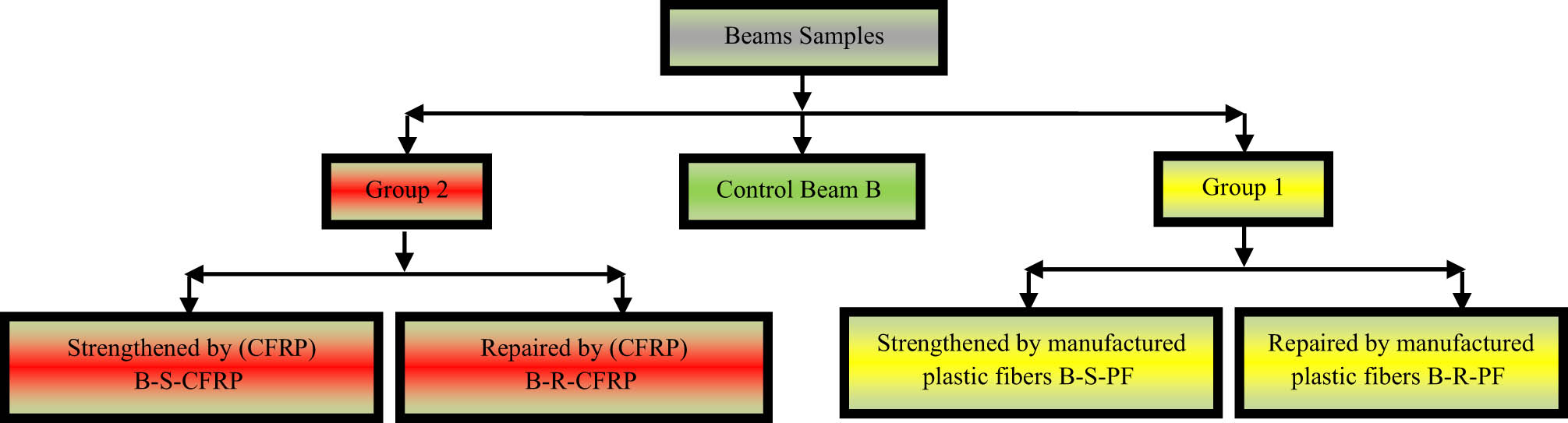
Schematic representation of beam samples.
2.4 Process of strengthening and repairing with CFRP and manufactured PF
After completing the casting of the beams and the curing period, the outer surface of the test beams should be thoroughly washed to remove dust particles and traces of oil left over from greasing the mold before casting [19]. Then, the beams are allowed to dry in the laboratory air. After that, the surface is polished by a special machine (kosra), the purpose of which is to remove a layer of cement mortar accumulated on the beam surface, which is usually weak, and the strong gravel layer extracted to prevent the phenomenon of fiber bands separating from the concrete surface [20]. After that, the CFRP strips and manufactured PF strips are prepared according to the required dimensions and numbers, and the fiber-cutting process is carried out using a sharp tool such as scissors. Then a mixture of epoxy Sikadur 330 C is prepared according to the instructions for using the material, where the amount required for work is prepared from the resin A and the hardener B, and each of them is mixed separately, and then mixed with each other in a ratio of two weights (1:4) [21] inside a plastic container and mix for at least 3 min in order to obtain a homogeneous mixture. The surface of the beam is treated at the bottom (in the tension area) with a layer of epoxy according to the recommendations of the company producing it using a trowel at a rate of 1.1 kg/m2, i.e., approximately 0.84 mm thick, then strips of CFRP or manufactured PFs are placed on the surface of the beam over the epoxy and pressed against the fibers. To ensure good saturation and to eliminate the voids that may occur between the fibers and the surface of the beam as a result of the presence of some air voids, as well as to obtain a constant thickness of the epoxy sheet, the outer surface of the fibers is coated with another layer of epoxy at a rate of 0.5 kg/m2 of fibers, i.e., with a thickness of approximately 0.38 mm. Beams are left for at least 7 days prior to examination to ensure complete hardening of the epoxy [22] (Figure 6).

Casting process and strengthening of reinforced concrete beams with fibers.
2.5 Test setup and loading condition
The beam models were tested in a device with a 1,000 kN force detection ability using a hydraulic jack and a computer. Two hinged supports supported the beam samples. All beams were tested until they broke down. The force applied to the test models was gradually increased by 5 kN. The test results, which were recorded from the beginning to the end of the tests, including the load of the first crack, the ultimate load, and deflections. In each load stage, remarks of crack enlargement on the concrete beam are indicated by a bottomless felt marker. The test setup and loading condition of beam samples are shown in Figure 7.

Test setup and loading condition for beam samples.
3 Results of beam samples
The results of the tests of the beam samples were analyzed on the basis of the cracking behavior, the load–deflection curves, the ultimate load, and the failure mode.
3.1 Cracking behavior
Crack formation was monitored throughout the tested beams to estimate the crack behavior of the strengthened or repaired beams in comparison to the control beam. However, this study pays close attention to the behavior of fiber separation from the concrete surface, the load of first crack, and the cracking pattern of all beams as follows.
3.1.1 Load of first crack
Strengthening with fiber for the reinforced concrete beams showed a significant increase in the load of first crack compared to the control beam (Table 5). The increase in the load of first crack for B-S-CFRP and B-S-PF was 27.8 and 22.2%, respectively. This means that CFRP and manufactured PF delay the appearance of cracks due to the limitation of the beam in the flexural region, and the efficiency of manufactured PF is almost the same as that of CFRP in increasing the first cracking load.
First cracking load and the amount of increase in it for the tested beams
| Beam samples | First cracking load (kN) | Increase in the first cracking load (%) |
|---|---|---|
| B | 18 | — |
| B-S-CFRP | 23 | 27.8 |
| B-S-PF | 22 | 22.2 |
3.1.2 Cracking pattern
In beam B, the first crack appeared due to an 18 kN load in the middle of the sample, i.e., in the region of maximum moment from the bottom, and then it started to rise toward the top, indicating a flexural crack, and as the load progressed, cracks began to appear next to the first crack and approached the support area. Flexure-shear cracks appeared near the support area and widened transversely until the beam failed (Figure 8). For the two beams strengthened with CFRP and manufactured PF (B-S-CFRP, B-S-PF), the first crack appeared by a load of 23 and 22 kN, respectively, in the middle of the beam, i.e., in the area of maximum moment. Figure 8 shows the number, length, and width of cracks have decreased due to CFRP or manufactured PF strengthening. For the two beams repaired using CFRP or manufactured PF (B-R-CFRP, B-R-PF), the number of cracks increased by a small amount because these two beams were loaded twice before repair and after repair. We also note that the efficiency of the manufactured PF is similar to that of CFRP in restricting and not spreading cracks due to loads.

Cracking pattern in the tested samples.
3.2 Load–deflection curves
To find out the structural performance of the tested beams, the load–deflection curves were drawn, as shown in Figure 9. In general, we can notice that the drawn curves consist of three stages. In the first stage, all the components of the tested beam (concrete, steel reinforcement, and fibers) are in the elastic stage. In the second stage, the concrete in the tensile area begins to crack, so the slope of this stage is less. In the third stage, which is the stage of failure, the steel reinforcement in the tensile region begins to yield and then fail, so its slope is less. For the two beams strengthened or repaired with CFRP (B-S-CFRP and B-R-CFRP), it shows a brittle behavior, as the greatest deflection decreased compared to the control beam by 40 and 36.6%, respectively. For the two beams strengthened or repaired with manufactured PFs (B-S-PF, B-R-PF), they showed ductile behavior as the deflection decreased compared to the control beam by a very small amount 6.3, and 2.8%, respectively. This behavior is considered a positive point for manufactured PF, as these fibers do not reduce ductility, and the failure is gradual and not sudden as in the strengthened or repaired by CFRP beams, so the failure is safer.

Load–deflection curves for the tested beams.
3.3 Failure mode and ultimate load
From Table 6, it can be seen that the amount of increase in the ultimate load of the beam strengthened by CFRP (B-S-CFRP) was 51% compared to the beam (B), and the quantity of increase in the ultimate load of the beam strengthened by manufactured PF (B-S-PF) was 45.45% compared to the beam (B). This indicates the efficiency of manufactured PF and its closeness to the efficiency of CFRP.
Failure mode and ultimate load for all the tested beams
| Beam samples | Ultimate load (kN) | Increasing in ultimate load (%) | Failure mode |
|---|---|---|---|
| B | 55 | — | Typical flexure failure |
| B-S-CFRP | 83 | 51 | Debonding failure |
| B-S-PF | 80 | 45.45 | Debonding failure |
| B-R-CFRP | 70 | 27.27 | Debonding failure |
| B-R-PF | 65 | 18.18 | Debonding failure |
For the two beams repaired using CFRP or manufactured PF (B-R-CFRP, B-R-PF), we note that both types of fibers were able to return the repaired beam to its ability to bear loads and repair the damage caused by loading by 70% of the failure load of the beam B with an increase in ultimate load by 27.27 and 18.18%, respectively. We also note that the efficiency of manufactured PFs in repairing structural members is almost the same as that of CFRP.
With regard to the failure mode of the control beam, it is a typical flexural failure and, as planned in this study, either the failure mode for the rest beams which strengthened or repaired by CFRP or manufactured PF is the failure of the fiber separation from the surface of the concrete, followed by a flexural failure. This kind of failure is common and expected in beams strengthened or repaired by fibers, due to the large number of cracks in the center of the beam, i.e., in the place of maximum moment, so these fibers begin to separate from the surface of the concrete without breaking or tearing.
4 Conclusions
The economic feasibility of the above study is to manufacture PFs from plastic waste locally with high efficiency and at a cost of 2 dollars per meter with a width of 50 cm, while the price of 1 m of CFRP with a width of 50 cm is more than 50 dollars. In addition, it is an effective and fast method to recycle plastic waste at a very low cost. The manufactured PFs have a low cost compared to the cost of the expensive CFRP. Manufactured PFs are quick to prepare and manufacture and do not need developed factories as needed by CFRP. It gives a ductile behavior, and the failure of the structural members strengthened with these fibers is a gradual failure, unlike the CFRP, whose behavior is brittle, and the failure of the strengthened members has a sudden and brittle failure, so the strengthened and repaired of the structural members with manufactured PFs are safer. These fibers PF can be woven in different directions (only in one direction, in two perpendicular directions, inclined at an angle of 45°), unlike the CFRP available in the local markets, which are woven in only one direction. The manufacture of these fibers is an effective and modern way to dispose of and recycle plastic waste, which is difficult to recycle. Manufactured PFs have the same properties as CFRP, such as lightweight, corrosion and rust resistance, high tensile strength, shock resistance, acid and alkali resistance, little thickness, weather resistance, ease of application and execution, and fire resistance because it is coated with a layer of epoxy.
-
Funding information: The authors state no funding involved.
-
Author contributions: All authors have accepted responsibility for the entire content of this manuscript and consented to its submission to the journal, reviewed all the results and approved the final version of the manuscript. HTN: developing the basic idea, conducting experiments, analyzing the results, writing the manuscript, and correspondence. MRKMA-B: contributing to analyzing the results, writing the manuscript, reviewing, and editing. AAE-b: contributing to writing, providing scientific sources, and reviewing. MMS: conducting experiments, contributing to writing, linguistic review and editing.
-
Conflict of interest: The authors state no conflict of interest.
References
[1] Al-Salem S, Lettieri P, Baeyens J. Recycling and recovery routes of plastic solid waste (PSW): A review. Waste Manage. 2019;29(10):2625–43.10.1016/j.wasman.2009.06.004Search in Google Scholar PubMed
[2] Markus K, David G, Andreas P, Cecilia H, Ulrika D. Everything you (don’t) want to know about plastics. Report by; 2019. Atursky ddsforeningen.Search in Google Scholar
[3] Theriault M, Benmokrane B. Effects of FRP reinforcement ratio and concrete strength on flexural behavior of concrete beams. J Compos Constr. 2016;2:7–16.10.1061/(ASCE)1090-0268(1998)2:1(7)Search in Google Scholar
[4] Ingle R, Masal R, Gargade A. Obtaining fuels from plastic waste. Int J Recent Innov Trends Comput Commun. 2014;2(4):2321–8169.Search in Google Scholar
[5] Alagusunda P, Harik I, Choo C. Flexural behavior of R/C beams strengthened with CFRP sheets or fabric. Research Report. KTC-02-13/SBR200-99-IF. Kentucky TranAsportation Center. University of Kentucky; 2018.Search in Google Scholar
[6] Chaallal O, Nollet MJ, Perraton D. Strengthening of reinforced concrete beams with externally bonded fiber- reinforced-plastic plates: Design guidelines for shear and flexure. Can J Civ Eng. 2011;25(4):692–704.10.1139/l98-008Search in Google Scholar
[7] Achintha PM, Burgoyne CJ. A fracture-mechanics model for debonding of external fiber reinforced polymer plates on reinforced concrete beams. The Tenth East-Pacific Conference on Structural Engineering and Construction. Bangkok, Thailand; 2016.Search in Google Scholar
[8] Rahimi H, Hutchinson A. Concrete beams strengthened with externally bonded FRP plates. ASCE. J Compos Constr. 2021;5(1):44–56.10.1061/(ASCE)1090-0268(2001)5:1(44)Search in Google Scholar
[9] Al-Sulaimani GJ, Sharif AM, Basunbul IA. Shear repair for reinforced concrete by fiber glass bonding. ACI Struct J. 2014;91:458–64.Search in Google Scholar
[10] Dai JG. Interfacial models for fiber reinforced polymer (FRP) sheets externally bonded to concrete. Ph.D dissertation. Japan: Hokkaido University; 2016.Search in Google Scholar
[11] Iraqi Specification Standards IQS No. 5. Portland cement, central agency for standardization and quality control. Baghdad, Iraq: Planning Council; 2004 (in Arabic).Search in Google Scholar
[12] Iraqi Specification Standards IQS No.45. Aggregate from natural sources for concrete and construction. Baghdad, Iraq: Central Agency for Standardization and Quality Control Planning Council; 2004 (in Arabic).Search in Google Scholar
[13] BS 1881-Part 116:1983. Method for Determination of Compressive Strength of Concrete Cubes. London: British Standards Institute BSI; 2018. p. 11.Search in Google Scholar
[14] ASTM C 496 C 496 M-21. Standard test method for splitting tensile strength of cylindrical concrete specimens. Annual Book of ASTM Standards. Vol. 04.02. West Conshohocken, PA, United States: Concrete and Aggregates; 2021. p. 5.Search in Google Scholar
[15] ASTM C 78-22. Standard test method for flexural strength of concrete (using simple beam with third-point loading). Annual Book of ASTM Standards. American Society for Testing and Materials; 2022.Search in Google Scholar
[16] ASTM A370-22. Standard test method and definition for mechanical testing of steel products. Annual Book of ASTM Standards. Vol. 01.01. Philadelphia, PA: ASTM; 2005.Search in Google Scholar
[17] Al-Mahaidi R. Use of FRP composites for strengthening of concrete buildings and bridges. Melbourne. Australia: Monash University; 2021.Search in Google Scholar
[18] American Concrete Institute, ACI Committee 318. Building Code Requirements for Structural Concrete (ACI 318-05) and Commentary (ACI 318R-05). Farmington Hills, MI: American Concrete Institute; 2015.Search in Google Scholar
[19] Abdel S, Grace GN, Soliman AK, Saleh KR. Behavior and ductility of simple and continuous FRP reinforced beams. J Compos Constr. 2008;2:186–94.10.1061/(ASCE)1090-0268(1998)2:4(186)Search in Google Scholar
[20] ACI Committee 440. Guide for the design and construction of externally bonded FRP systems for strengthening concrete structures. Detroit: American Concrete Institute; 2022.Search in Google Scholar
[21] Arnes RA, Mays GC. Fatigue performance of concrete beams strengthening with CFRP plates. J Compos Constr. 2009;3(2):215.10.1061/(ASCE)1090-0268(1999)3:2(63)Search in Google Scholar
[22] Carolin A. Carbon fiber reinforced polymers for strengthening of structural elements. Ph.D. Thesis. Sweden: University of Lulea; 2013. p. 194.Search in Google Scholar
© 2024 the author(s), published by De Gruyter
This work is licensed under the Creative Commons Attribution 4.0 International License.
Articles in the same Issue
- Research Articles
- Flutter investigation and deep learning prediction of FG composite wing reinforced with carbon nanotube
- Experimental and numerical investigation of nanomaterial-based structural composite
- Optimisation of material composition in functionally graded plates for thermal stress relaxation using statistical design support system
- Tensile assessment of woven CFRP using finite element method: A benchmarking and preliminary study for thin-walled structure application
- Reliability and sensitivity assessment of laminated composite plates with high-dimensional uncertainty variables using active learning-based ensemble metamodels
- Performances of the sandwich panel structures under fire accident due to hydrogen leaks: Consideration of structural design and environment factor using FE analysis
- Recycling harmful plastic waste to produce a fiber equivalent to carbon fiber reinforced polymer for reinforcement and rehabilitation of structural members
- Effect of seed husk waste powder on the PLA medical thread properties fabricated via 3D printer
- Finite element analysis of the thermal and thermo-mechanical coupling problems in the dry friction clutches using functionally graded material
- Strength assessment of fiberglass layer configurations in FRP ship materials from yard practices using a statistical approach
- An enhanced analytical and numerical thermal model of frictional clutch system using functionally graded materials
- Using collocation with radial basis functions in a pseudospectral framework to the analysis of laminated plates by the Reissner’s mixed variational theorem
- A new finite element formulation for the lateral torsional buckling analyses of orthotropic FRP-externally bonded steel beams
- Effect of random variation in input parameter on cracked orthotropic plate using extended isogeometric analysis (XIGA) under thermomechanical loading
- Assessment of a new higher-order shear and normal deformation theory for the static response of functionally graded shallow shells
- Nonlinear poro thermal vibration and parametric excitation in a magneto-elastic embedded nanobeam using homotopy perturbation technique
- Finite-element investigations on the influence of material selection and geometrical parameters on dental implant performance
- Study on resistance performance of hexagonal hull form with variation of angle of attack, deadrise, and stern for flat-sided catamaran vessel
- Evaluation of double-bottom structure performance under fire accident using nonlinear finite element approach
- Behavior of TE and TM propagation modes in nanomaterial graphene using asymmetric slab waveguide
- FEM for improvement of damage prediction of airfield flexible pavements on soft and stiff subgrade under various heavy load configurations of landing gear of new generation aircraft
- Review Article
- Deterioration and imperfection of the ship structural components and its effects on the structural integrity: A review
- Erratum
- Erratum to “Performances of the sandwich panel structures under fire accident due to hydrogen leaks: Consideration of structural design and environment factor using FE analysis”
- Special Issue: The 2nd Thematic Symposium - Integrity of Mechanical Structure and Material - Part II
- Structural assessment of 40 ft mini LNG ISO tank: Effect of structural frame design on the strength performance
- Experimental and numerical investigations of multi-layered ship engine room bulkhead insulation thermal performance under fire conditions
- Investigating the influence of plate geometry and detonation variations on structural responses under explosion loading: A nonlinear finite-element analysis with sensitivity analysis