Performance analysis on the structure of the bracket mounting for hybrid converter kit: Finite-element approach
-
Ma’ruf Yanuar Effendi
 ,
Eko Prasetya Budiana
,
Eko Prasetya Budiana

Abstract
An electric motor mounting bracket is used in electric vehicles, especially hybrid ones using a parallel hybrid configuration. This study aims to analyze the strength and performance of the initial design and topology optimized design. This study uses the finite-element method (FEM) in the bracket design modeling by applying topology optimization. The topology optimization results show a mass reduction of 50% from the initial design mass. In the case of static loading, the results of optimized design 2 have a stress of 142.19 MPa and a safety factor of 3.09. While optimized design 1 has a stress of 313.8 MPa and a safety factor of 1.4. In terms of dynamic loading, the initial design, optimized design 1, and optimized design 2 have the first natural frequency, which is higher than the operating frequency of the electric motor, respectively, 100.49, 69.043, and 74.864 Hz. Optimized design 1 has the lowest natural frequency and the highest amplitude compared to the initial design, and optimized design 2 has lower damping characteristics. The study results conclude that optimized design 2 is superior in static and dynamic loading.
1 Introduction
Vehicles in Indonesia are growing rapidly, especially in big cities. This is because the need for transportation is vital for community mobilization. Most of the vehicles used by the public generally rely on fossil fuels. However, scientists predict that fossil fuel reserves will be depleted by 2050. The efficiency of fossil fuels is low, with only 25% being utilized, while the rest is wasted as pollution [1]. The increasing growth of motorized vehicles will have a significant impact on pollution levels [2,3]. Therefore, efforts are needed to reduce pollution rates in Indonesia, aside from relying solely on public transportation provided by the government.
The trend of electric vehicles has started to emerge in Indonesia as a means to reduce pollution levels. The concept of electric vehicles aims to achieve zero emissions and minimize pollution problems [4,5]. However, Indonesia’s transition from conventional motorized vehicles to electric vehicles is progressing relatively slowly. The public has been hesitant to accept it due to drawbacks such as high initial capital costs and limited driving range of 100–200 km before the battery needs to be recharged [6,7].
Hybrid electric vehicle (HEV) is a type of vehicle that combines the performance of an internal combustion engine vehicle (ICEV) with an electric motor. HEVs serve as a temporary solution until the community fully embraces the use of pure electric vehicles (PEVs) [5]. The advantages of HEVs include extending the mileage of electric vehicles by two to four times and offering quick refueling with petrol. The main drawbacks of HEVs are the compromise on the zero-emission concept and increased complexity. However, HEVs are significantly less polluting and have lower fuel consumption compared to ICEVs, while maintaining a similar driving range [8,9].
HEVs are categorized into two types: series hybrid and parallel hybrid. However, since their development in 2000, HEVs have been further classified into series hybrid, parallel hybrid, series-parallel hybrid, and complex hybrid [10]. A parallel hybrid allows both the internal combustion engine and electric motor to deliver power in parallel to drive the wheels [11], as they are typically connected to the drive shaft. The propulsion power can be supplied by the engine, the electric motor, or both.
In a parallel hybrid, the internal combustion engine and electric motor can directly transmit torque to the driven wheels through a mechanical clutch. The mechanical clutch can take the form of a gearbox, pulley-belt system, chain-sprocket system, or a shaft [11,12]. An additional device or structure is required to convert a conventional motorcycle into a hybrid one. This comes in the form of a holder or bracket, which is a component of the vehicle’s structural sub-frame connected to the motorcycle’s main frame, as shown in Figure 1. Brackets are used to support the engine, electric motors, and other components.
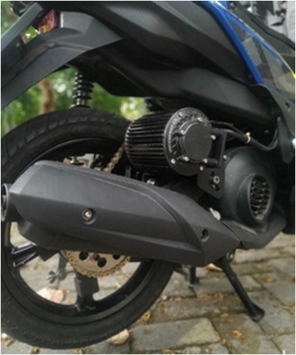
Location of electric motor and bracket in a hybrid electric vehicle.
Researchers have applied topology optimization techniques to various components used in automobiles. Kalsi et al. [13] conducted a study on optimizing compressor brackets in passenger vehicles. The aim of this study was to enhance bracket stiffness while reducing mass and production costs. Gülbahçe et al. [14] carried out research on topology optimization of jet engine brackets using the finite-element method. The optimization resulted in a significant weight reduction of up to 76.7% for the brackets. Neelakandan et al. [15] investigated housing brackets for electric motor starters using the finite-element method with the assistance of ANSYS Software. The design engineering process involved optimization through thickness reduction, changing the chamfer geometry to a radius, and removing material structures unaffected by force. Sudke and Kondhalkar [16] also optimized the design of vehicle suspension brackets by selectively removing material from areas with low stress, resulting in lighter bracket masses. Dhillon et al. [17] explored the engine mounting bracket of an SAE formula car using topology optimization to reduce mass. They also introduced ribs to help reduce maximum deflection by 30.5% in the most critical loading scenario.
Previous studies have primarily focused on static simulations of the initial bracket design, but in reality, the bracket is subjected to dynamic loading. Furthermore, previous bracket designs have shown potential for further optimization. Therefore, this study aims to examine the response of the bracket design to both static and dynamic loading, as well as to compare the performance of the initial bracket design with the optimized design achieved through topology optimization.
2 Methods
2.1 The work of principle
The study commenced by validating the data obtained from previous research. The validation process involved precisely replicating the research design of Kalsi et al. [13] using Autodesk Fusion 360 software for model creation and ANSYS Workbench 19 software for simulation. Data validation was conducted to compare the simulation results, particularly the maximum Von Mises stress, with the most recent simulation. Upon completing the latest simulation, a comparison revealed a deviation of less than 5% compared to the research conducted by Kalsi et al. [13]. Data validation was crucial to ensure the validity of the simulated design and to establish the reliability of the resulting data. Following the data validation process and understanding the degree of deviation, the subsequent step involved collecting data using both the initial and optimized designs.
The research then proceeded by gathering static data, which included total deformation, mass, and Von Mises stress. Dynamic data, such as natural frequency, mode shape, and frequency response curve, were also obtained for both the initial design and the optimized design derived from the results of topology optimization.
One commonly used analytical approach is the beam theory, which is applicable to thin-walled structures with high aspect ratios. The beam theory assumes that the structure can be modeled as a series of beams subjected to bending and axial loads. The analytical equations can be derived based on the properties of the material, cross-sectional shape, and loading conditions.
Another analytical approach is the plate theory, which is applicable to flat structures subjected to bending and shear loads. The plate theory assumes that the structure can be modeled as a thin plate subjected to various loading conditions. The analytical equations can be derived based on the properties of the material, plate geometry, and loading conditions.
For more complex structures, such as bracket mounting, finite-element analysis is commonly used. Finite-element analysis is a numerical method that discretizes the structure into small elements and solves the equations of motion using matrix methods. The mechanical response of the structure can be predicted by solving the governing equations, such as the equations of static equilibrium or the dynamic equations of motion. Several analytical formulations are available in the literature for predicting the mechanical response of structures. The appropriate analytical approach depends on the type of structure and loading conditions. In this topic, the finite-element analysis was used to predict the mechanical response of the bracket mounting under different loading conditions.
The Euler–Bernoulli beam theory is a commonly used analytical approach for modeling slender beams subjected to bending and axial loads [18]. The deflection and bending stress of the beam can be calculated using the following equations:
Deflection:
Bending stress:
where w(x) is the deflection at point x,
Deflection:
Bending stress:
where
The Kirchhoff plate theory is a commonly used analytical approach for modeling thin, flat plates subjected to bending and shear loads [20]. The deflection and bending stress of the plate can be calculated using the following equations:
Deflection:
Bending stress:
where
2.2 Specification of hybrid electric vehicles
A hybrid electric vehicle uses a Yamaha Mio M3 base and an electric motor with the QS Mid Drive Motor 1,000 W brand. The specifications obtained are from the manufacturer’s official website. We assume that the average human weight in Indonesia is 60 kg. Table 1 shows the specification of a hybrid electric vehicle.
Specification of hybrid electric vehicles
| Variables | Value |
|---|---|
| Torque on the electric motor (Nm) | 25.2 |
| Rpm of electric motor @25.2 Nm | 292 |
| Gear ratio | 3.2:1 |
| Torque on wheel (Nm) | 81 |
| Total mass (vehicle, 1 passenger, hybrid converter device) (kg) | 94 + 60 + 20 |
| 174 kg | |
| Rear wheel size | 80/90–14 |
| Tire profile height (mm) | 72 |
| Wheel diameter (mm) | 499.6 |
| Wheel radius (mm) | 249 |
2.3 Design and topology optimization setup
The simulation implementation utilized the finite-element method with ANSYS Workbench 19 and Fusion 360 software for creating a three-dimensional model. Autodesk Fusion 360 is recognized as one of the top software applications for solid modeling, while ANSYS is widely regarded as the premier simulation software for analyzing research designs [21]. The finite-element method enables the solution of various static and dynamic engineering problems, ranging from simple beam structural stress analysis (1D) to complex machines with substantial capacities (3D), as well as dynamic responses involving mechanical, electrical, magnetic, or thermal factors [22].
Figure 2 illustrates the dimensions of the initial design. The topology optimization process was then applied to the structure of the initial design to generate two optimized designs: optimized design 1 and optimized design 2, which incorporates ribs as the structural foundation (as shown in Figure 3). Topology optimization aims to improve the structural shape in response to force distribution and reduce excessive material, ultimately resulting in a lighter weight for the optimized design.
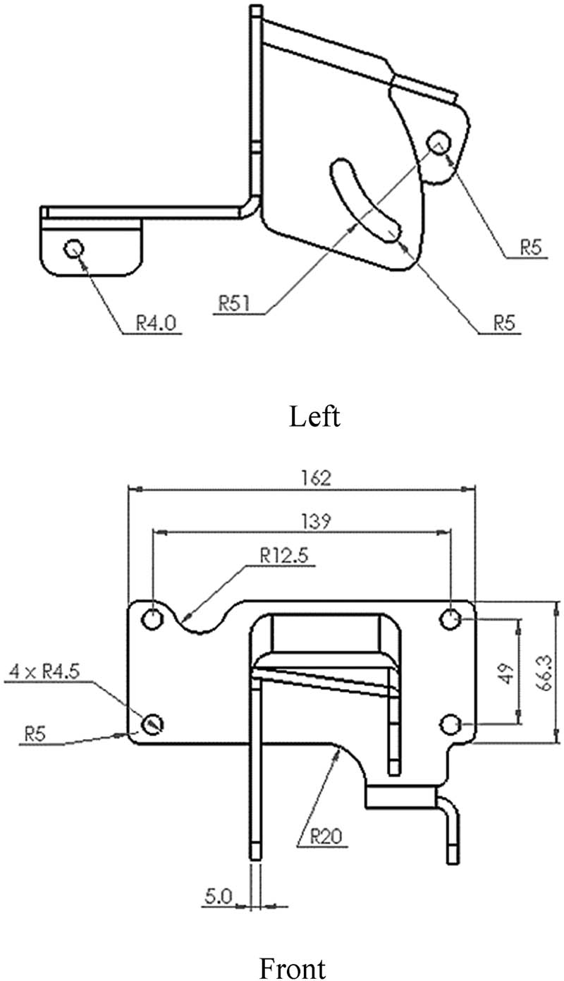
Initial design bracket. Left, Front.

(a) Base structure for topology optimization of optimized design 1. (b) Base structure for topology optimization of optimized design 2.
Topology optimization is carried out by maintaining the mass of the bracket structure by 50% from the initial design base, which results in the structure of optimized design 1, and maintaining 35% mass from the initial design base with added ribs so that the final result of optimized design 2 has the same mass as optimized design 1. In topology optimization, adjustments are made to the ANSYS Workbench 19 software in the form of selecting a design optimization area for all bracket parts and selecting an optimization exclusion area in the form of bolt holes and support because they are part of the reference that should not be removed or affected by topology optimization. Figure 4 shows the topology optimization setup’s design and exclusion regions.
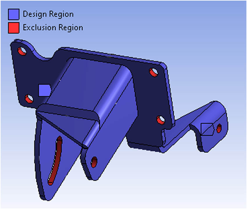
Design region and exclusion region.
Topology optimization involves iteratively removing elements from the initial design while maintaining its performance until the desired objective is met. The optimization process can be formulated as an optimization problem with constraints, such as volume constraints and stress constraints. These are some equations and calculations involved in the finite-element analysis and topology optimization of the bracket mounting for the hybrid converter kit. The specific equations and calculations used may vary depending on the specific software and modeling approach used in the analysis [23].
Topology optimization is a computational design method used to optimize the material distribution of a structure to achieve a specific objective, such as minimizing mass or maximizing stiffness, subject to constraints such as stress, displacement, or volume [24]. Here, topology optimization is used to optimize the design of the bracket mounting for the hybrid converter kit.
The topology optimization process involves defining an objective function and constraints, as well as specifying the material properties, element types, and meshing parameters. The objective function is a mathematical expression that describes the performance metric to be optimized, such as the mass of the bracket. The constraints are mathematical expressions that limit the allowable stress, displacement, or volume of the bracket [24,25].
The objective function is to minimize the mass of the bracket while maintaining a certain level of performance. The constraints are the stress and volume constraints. The stress constraint is based on the yield strength of the bracket material, and the volume constraint is used to ensure that the bracket fits within the available space. The topology optimization process generates a design that maximizes the objective function subject to the constraints. In this topic, the optimized designs show a significant reduction in mass while maintaining a certain level of performance [25].
2.4 Materials
Materials often used for brackets are aluminum and mild steel [26]. In this study, mild steel was chosen for several reasons, such as material properties and ease of obtaining the material. Mild steel has properties and characteristics such as ductile, malleable, and good tensile strength [27]. Table 2 shows the difference in yield strength values with a difference of 275 MPa, so mild steel has better strength than aluminum.
Properties of materials [10]
| Materials | Variables | Value |
|---|---|---|
| Aluminum | ρ, Density (kg m−3) | 2,820 |
| E, Young’s modulus (GPa) | 71 | |
| σ y , Yield strength (MPa) | 165 | |
| v, Poisson’s ratio | 0.33 | |
| Mild steel | ρ, Density (kg m−3) | 7,860 |
| E, Young’s modulus (GPa) | 205 | |
| σ y , Yield strength (MPa) | 440 | |
| v, Poisson’s ratio | 0.3 |
2.5 Meshing
The generated model was discretized using tetrahedral elements. Figure 5 shows a meshed model of the initial design. The mesh details included the following: relevance center: fine, smoothing: high, transition: fast, initial size seed: assembly, element size: 2 mm, defeaturing size: default, and size function: adaptive. The quality of the mesh is determined by using different quality parameters given by Gokhale et al. [28]. This parameter determines the deviation of the element from its ideal shape. Table 3 shows the value of parameters for the resulting model. Different parameter values are reasonable within the specified limits according to the ideal value [13].
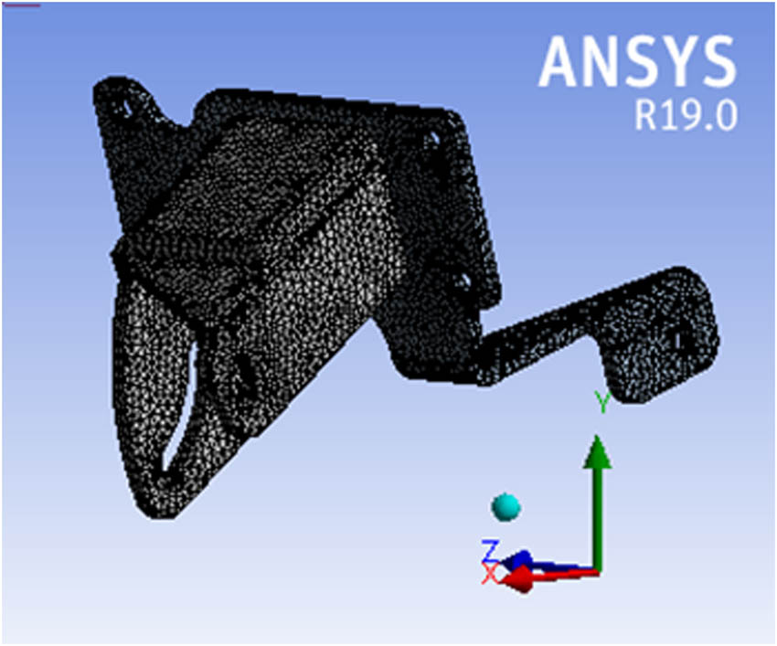
Meshed model of initial design.
Parameter mesh quality
| Parameter | Value |
|---|---|
| Aspect ratio | 2.08 |
| Jacobian | 1.02 |
| Skewness | 0.33 |
2.6 Load and constraint
The boundary conditions used to analyze the static and dynamic loading of the bracket are to place the bolt holes attached to the crankcase and the default exhaust mount as cylindrical support and the bolt holes for the bracket support rods as frictionless support so that the bracket position does not move. The bolt holes or surface brackets that hold the electric motor are given remote points at the coordinates of 37,719 x-axis, 67.11 y-axis, and 32.073 z-axis according to the ANSYS Workbench 19 software coordinate system. Remote point coordinates are obtained from the center of mass of the electric motor according to the coordinate system on the Fusion 360 software. Remote points are used to locate static and dynamic forces in the simulation. Figure 6 shows the remote point and the support.

(a) Remote point, and (b) support.
The static loading force used is a force of 76.4868 N as a result of multiplying the weight of the electric motor with gravity, where the electric motor weight is 7.8 kg. The force value is obtained from the basic equation of force:
In addition, the maximum torque produced by the electric motor is used as a static load assuming the torque is in a steady state. The torque released is 25.2 Nm at a rotational speed of 292 rpm on the front sprocket to find the value of the chain tension so that a force can be applied to the remote point:
As for the chain tension, it is obtained by calculation. The value of the tangential driving force is obtained through the calculation in Eq. (2). At the same time, the tension in the chain due to sagging is obtained through the calculation in Eq. (3). Furthermore, a moment load of 51,428 Nmm for the X component and − 57,040 Nmm for the Y component is also applied as a result of the chain tension obtained through the calculation of the static equilibrium equation placed at the remote point according to the dimensions of the electric motor and the coordinate system. Figure 7 shows the application of static loading forces in a static structural simulation.
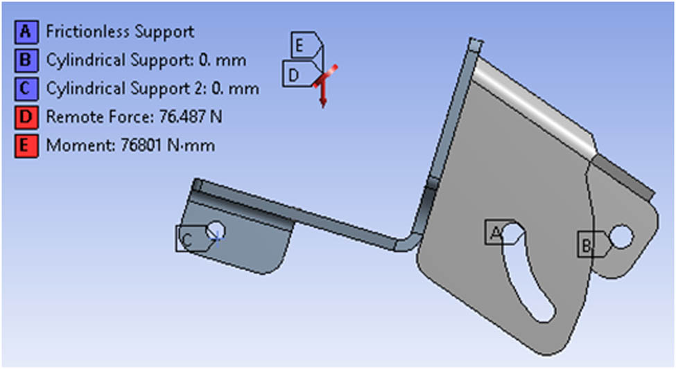
Boundary condition of static structural.
In the dynamic simulation, namely, modal analysis, the load used is in the form of a point mass given to a remote point, which is 7.8 kg. In comparison, the harmonic response analysis uses a load of point mass and an acceleration of 2,025 mm/s2 to the x-axis following the direction of the motorcycle’s acceleration movement toward the front in real conditions. The acceleration value is obtained from the basic equation of force (1). The force is obtained through the calculation of the force caused by the torque on the wheel with the assumption that the coefficient of friction is 0.6. Then, the mass assumes the weight distribution on the rear wheels is 55% of the total mass of a hybrid electric vehicle with one passenger. Figure 8 shows the boundary conditions specified in modal analysis (Figure 8a) and harmonic response analysis (Figure 8b).
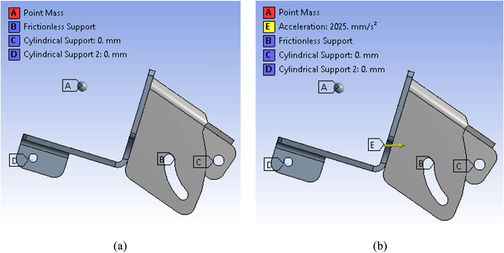
Boundary condition of (a) modal analysis and (b) harmonic response analysis.
3 Results and discussion
This study aims to design an electric motorcycle bracket as an additional device to convert an oil-fueled motorcycle into a plug-and-play hybrid motorcycle so that it does not change the default components. The design concept carried out in this study is to create a new bracket design that is lighter than the initial design through topological optimization methods while still considering the strength of static and dynamic loading. It is intended to cut material costs and reduce the weight of the bracket so that the acceleration of the motorcycle can be increased due to the reduction in mass borne by the electric motor. In order to provide an in-depth analysis technique regarding bracket design for mass reduction, it is necessary to discuss the study’s results supported by several other studies. This chapter presents the data through pictures and graphs and their explanations. It consists of a stress contour, a deformation contour, a natural frequency, and a frequency response graph.
3.1 Topology optimization
After topology optimization is done, the bracket profile will change depending on the software’s distribution of forces and setup. The topology optimization results occur in areas with relatively low-stress values because they aim to avoid material damage. In general, the results of topology optimization in ANSYS software have a rough structure, so a smoothing process or design changes must be carried out manually to avoid the occurrence of high-stress values due to rough contours resulting from the topology optimization. Figures 9 and 10 show the topology optimization results after completing this study’s profile. Table 4 shows a final comparison mass of the design.
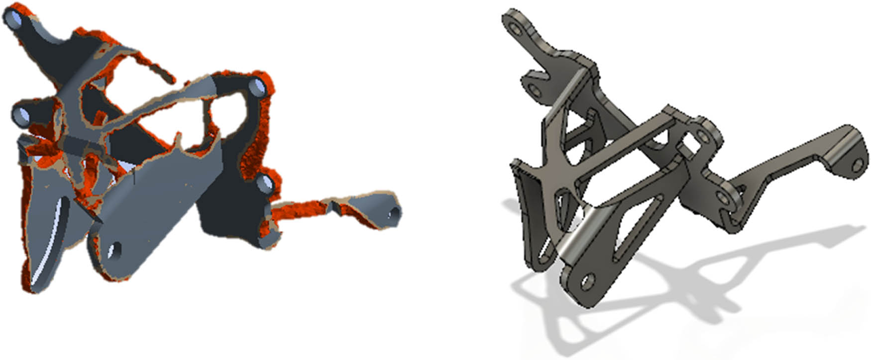
Optimized design 1.
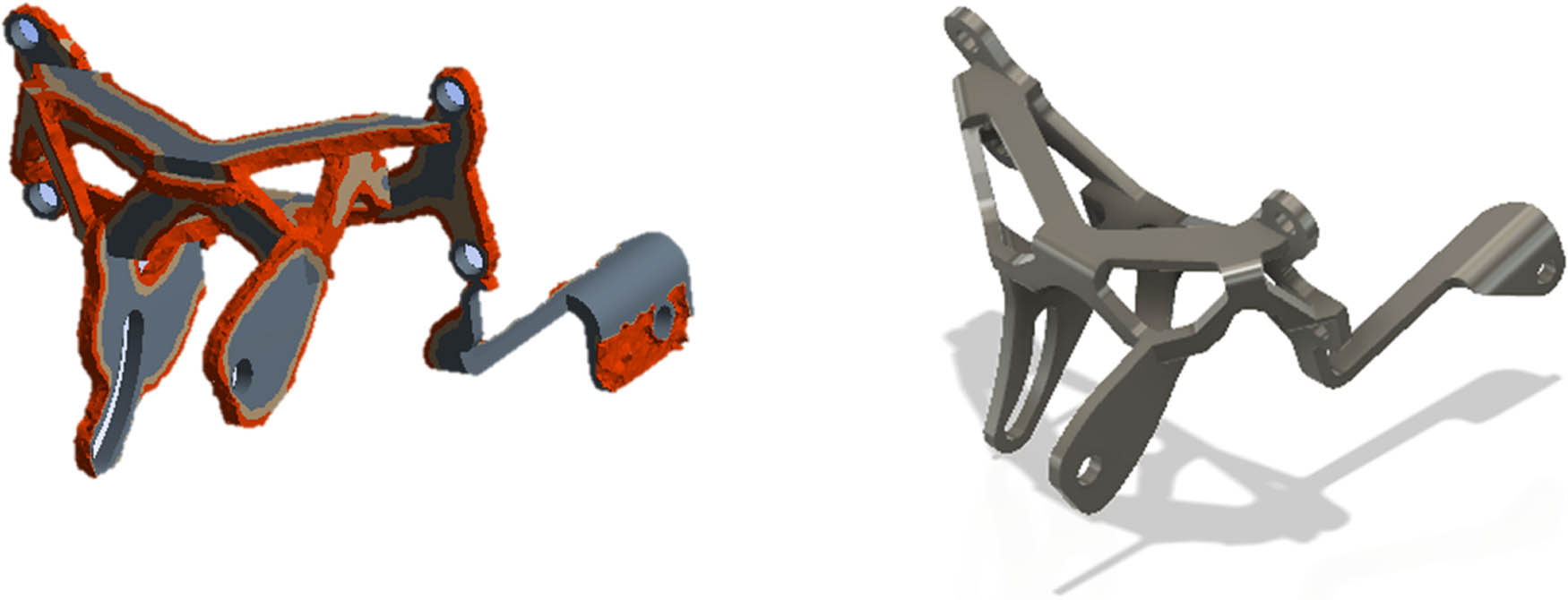
Optimized design 2.
Comparison mass of design
| Parameter | Initial design | Optimized design 1 | Optimized design 2 |
|---|---|---|---|
| Mass (kg) | 1.1423 | 0.5762 | 0.5753 |
3.2 Static structural analysis
Static structural simulation in ANSYS software is used to determine the strength of the bracket design against static loading. The static load is a load that acts continuously on a structure. Static loads are also assumed to be loads that slowly arise and have steady-state variables. Static structural simulation is carried out by applying the parameters obtained from the previous validation simulation. The load and the support type are given per the boundary conditions described in the research method. Static structural simulations were carried out on the initial design structure, optimized design 1, and optimized design 2 to determine the difference in the maximum stress value and total deformation between design variations.
The maximum stress in the initial design is shown in Figure 11. The maximum stress value in the initial design is 201.39 mPa at the welding location. It is because, in that position, it is a meeting of two bodies that are tangent to each other, so they get significant stress due to the application of the load. The total deformation is shown in Figure 11b, where the initial design experienced a total deformation of 0.205 mm at the outermost position of the cross-section because that position is a location that has a considerable distance from the supporting rod so that the most significant deflection occurs at the end of the structure due to the applied load.

The result static structural analysis of initial design: (a) von Mises stress, mPa; and (b) total deformation, mm.
Static structural simulation of optimized design 1 produces a maximum stress of 313.8 mPa. Figure 12a shows the von Mises stress of optimized design 1. The stress value has increased by 55.8% compared to the maximum initial design stress. It is due to the effect of topological optimization where material reduction is between the supports, which results in lower structural stiffness than the initial design stiffness, so an increase in stress values occurs in that area. Figure 12b shows the total deformation value in optimized design 1 of 0.369 mm. Again, the increase in the deformation value by 80% is due to the decreased stiffness of the structure due to the material reduction effect from topology optimization, so that the deflection increases.

The result static structural analysis of optimized design 1: (a) von Mises stress, mPa; and (b) total deformation, mm.
Optimized design 2 has a maximum stress of 142.19 mPa. Figure 13a shows the von Mises stress of optimized design 2. The maximum stress value in optimized design 2 is lower than the initial design and optimized design 1. Compared to the initial design stress, optimized design 2 has a stress decrease of 29.4%. It is because the results of topology optimization get a structural form with a better distribution of forces compared to other design variations, so the stress value obtained is also lower. The total deformation is also observed in optimized design 2. The total deformation of optimized design 2 is 0.089 mm or a decrease of 56.6% compared to the initial design. The decrease in deformation is caused by the position of the support beam being closer to the loading position so that the deflection is smaller. Figure 13b shows the total deformation of optimized design 2.

The result static structural analysis of optimized design 2: (a) von Mises stress, mPa; and (b) total deformation, mm.
Overall, three design variations can be safe in receiving static loads for both the maximum stress and total deformation because the maximum stress value is below the allowable stress limit of the material properties. However, optimized design 2 has superior strength compared to other design variations because it has a lower maximum stress and total deformation and the highest safety factor value. Table 5 shows the results of the overall static structural analysis.
Comparison of static structural result
| Parameter | Initial design | Optimized design 1 | Optimized design 2 |
|---|---|---|---|
| Von Mises stress (MPa) | 201.39 | 313.8 | 142.19 |
| Total deformation (mm) | 0.205 | 0.369 | 0.089 |
| Safety factor | 2.18 | 1.4 | 3.09 |
3.3 Modal analysis
Modal analysis is carried out to determine the characteristics of design variations in the case of vibration. The modal analysis results are in the form of natural frequencies and modes of the bracket structure design. The natural frequency value is as far as possible away from the vibration frequency value from the vibration source to avoid resonance. The resonance can cause significant vibrations that can damage the structure due to material failure. In this study, the first four natural frequencies were taken as a comparison between design variations. A mode shape is a deflection pattern related to a particular natural frequency and represents the relative displacement of all parts of a structure for that particular mode.
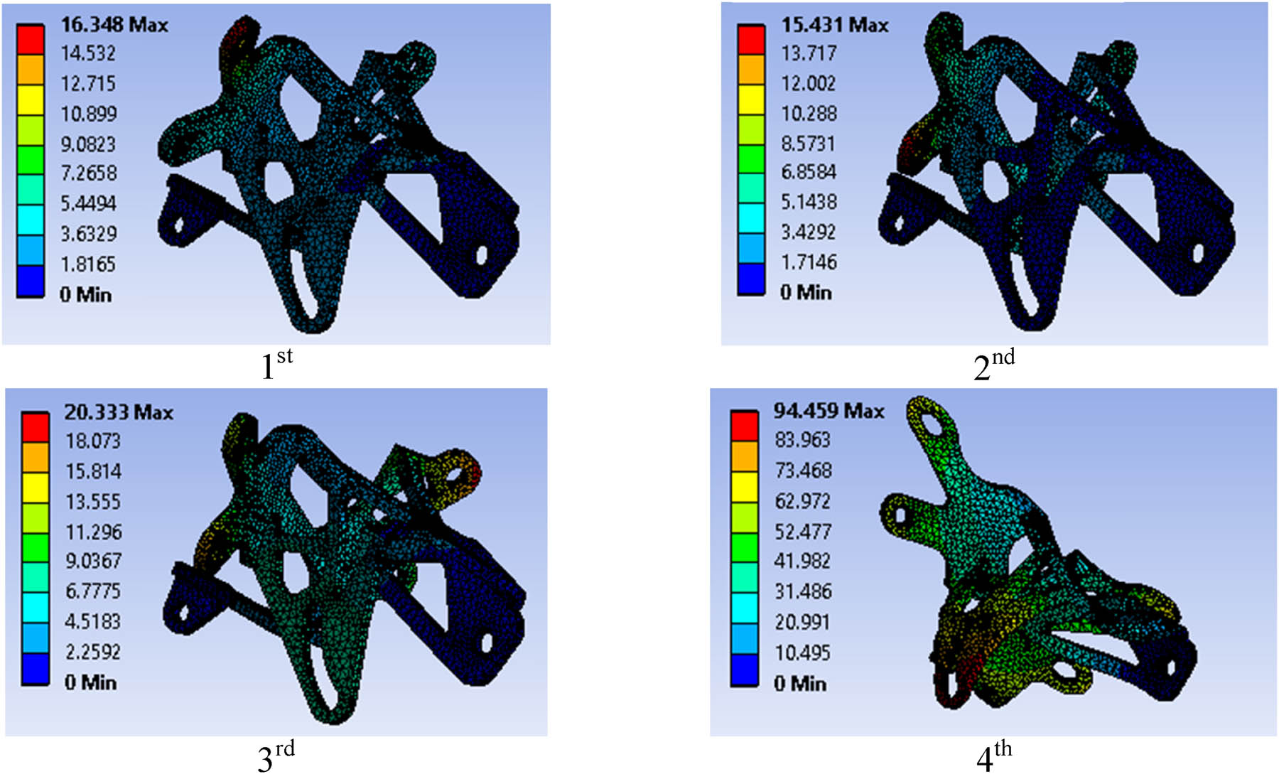
After simulating the modal on the initial design and optimized design, the natural frequency and mode shape are obtained. The first natural frequencies of the initial design, optimized design 1, and optimized design 2 are 100.49, 68.196, and 74.864 Hz, respectively. Table 6 shows the natural frequencies of variation design. Both experienced a decrease in natural frequency values for optimized design. It shows that the stiffness and mass of the optimized design are lower than the initial design. It is because the natural frequency of the initial design and optimized design is above the operating frequency range of the electric motor, so it has better vibration isolation. However, optimized design 1 has the lowest natural frequency value of 68 Hz compared to the initial design natural frequency and optimized design 2. Figures 14–16 show the mode shapes of the initial design and optimized designs 1 and 2, respectively.
Comparison of natural frequencies result
| Natural frequency | Initial design | Optimized design 1 | Optimized design 2 |
|---|---|---|---|
| 1st | 100.49 | 69.04 | 69.04 |
| 2nd | 112.13 | 73.89 | 73.89 |
| 3rd | 236.82 | 136.82 | 136.82 |
| 4th | 560.12 | 889.58 | 889.58 |

Shapes mode of the initial design.
Shapes mode of optimized design 1.

Shapes mode of optimized design 2.
The difference in natural frequency values is influenced by the mass and stiffness of each design variation. It is because the stiffness of a structure is affected by the material’s modulus of elasticity. However, in this study, all three design variations use the same material, so the structure’s geometry influences the difference in stiffness.
3.4 Harmonic response analysis
Harmonic response analysis is performed on the response of a mechanical structure at a certain frequency to withstand sinusoidally changing dynamic loads with time. It helps the designer verify that the structure can cope with resonance, fatigue, and other effects under forced vibration. In this study, the dynamic load is the acceleration experienced by a hybrid motorcycle. The acceleration value used is 2,025 mm/s2. The acceleration value is obtained by calculating the force caused by the maximum torque of the electric motor to the total weight of the hybrid motorcycle.
Harmonic response analysis is also called frequency response analysis. The result of the harmonic response analysis is an amplitude–frequency curve. The amplitude in this study is the displacement distance of the structure from the equilibrium position when resonance occurs at the natural frequency. This analysis is used to determine the difference in vibration characteristics of each design variation. The amplitude–frequency curve in this study is oriented on the x-axis according to the direction of the acceleration force. The harmonic response analysis simulation results in the initial design obtained a maximum amplitude of 0.0019 mm at a frequency of 100.49 Hz as the first natural frequency.
Furthermore, in optimized design 1, the maximum amplitude value is 0.0057 mm at 69.043 Hz. While optimized design 2 obtained a maximum amplitude of 0.0018 mm at a frequency of 74,864 Hz. Optimized design 1 has a larger amplitude than the other two design variations of the three design variations, so the resulting vibration is also more significant. Overall the most significant amplitude value is at the first natural frequency. Figure 17 shows the results of the amplitude–frequency curve.

Amplitude–frequency response.
3.5 Bracket design performance analysis
Performance analysis is carried out to determine how much the design capability of the electric motor bracket design under conditions of static loading and dynamic loading. This analysis is used to determine the superior design of each design variation when applied to a hybrid motorcycle.
In the case of static loading, the parameters used to determine the superior performance include the mass and safety factor of the bracket design. Based on the data shown in Table 4, optimized designs 1 and 2 have a mass that is 50% lighter than the initial design. Theoretically, the reduction in the structure’s weight in a motor vehicle can affect the acceleration characteristics. The general equation can know this force, where the value of acceleration is inversely proportional to mass. Therefore, the lighter the load borne from the vehicle, the acceleration will accelerate. Therefore, based on the mass parameter, optimized designs 1 and 2 are superior to the initial design.
The mass parameter alone is insufficient to determine the optimal design among the three design variations, as the mass differences between optimized designs 1 and 2 are insignificant. Therefore, the safety factor is also taken into consideration when evaluating the bracket design’s performance. The safety factor indicates the structural safety against static loading and is calculated as the ratio of yield strength to the stress experienced by the bracket design. A higher safety factor value indicates a better capacity to withstand loading. For structures made of ductile materials, a safety factor in the range of 1.25–2 is considered safe. Based on the data presented in Table 5, optimized design 2 demonstrates superior performance compared to the other two design variations due to its highest safety factor value of 3.09. Overall, all designs can be considered safe for static loading since the safety factor exceeds 1.25. Considering the mass, stress, and safety factor parameters, it can be concluded that optimized design 2 exhibits superior performance for static loading.
Regarding dynamic loading, the first natural frequency is used to assess the bracket design’s performance, considering the electric motor’s frequency of operation. According to the electric motor manufacturer’s datasheet, the maximum achievable rotational speed is 677.6 rpm. Calculations based on the rotational speed equation indicate a resulting frequency of 56.4 Hz, which represents the frequency range during electric motor operation.
Resonance can cause structural failure when the structure vibrates at its natural frequency. In this study, resonance can occur if the electric motor operates at the bracket system’s natural frequency. However, based on the data presented in Table 6, optimized designs 1 and 2 have natural frequencies of 69,043 and 74.864 Hz, respectively, which are outside the operating range of the electric motor (56.4 Hz). By utilizing the electric motor’s rotational speed equation, it is determined that the electric motor operates at a frequency of 54.6 Hz when rotating at 655 rpm. Therefore, optimized designs 1 and 2 do not experience resonance, even when the electric motor operates at its maximum rotational speed of 655 rpm. Considering the natural frequency parameter, higher values indicate superior performance in terms of vibration. Based on the curve depicted in Figure 17, the initial design outperforms optimized designs 1 and 2, exhibiting a larger first natural frequency value and smaller amplitude.
To determine the optimal final design, performance under both static and dynamic loading is taken into account. Based on the assessment of performance in static and dynamic loading scenarios, it can be concluded that optimized design 2 is the best choice for application in hybrid motorcycles. This design offers a weight reduction of 50%, the highest safety factor of 3.09, and sufficient strength for dynamic loading, as its first natural frequency of 74.864 Hz exceeds the electric motor’s operating range of 56.4 Hz, thereby avoiding the resonance phenomenon.
4 Conclusion
The bracket design optimization has been conducted using topology optimization methods. In the static loading analysis, the initial design exhibits a maximum stress of 201.39 MPa, a total deformation of 0.205 mm, and a safety factor of 2.18. Optimized design 1 demonstrates a stress of 313.8 MPa, a total deformation of 0.369 mm, and a safety factor of 1.4. Meanwhile, optimized design 2 shows a stress of 142.19 MPa, a total deformation of 0.089 mm, and a safety factor of 3.09. In the dynamic loading analysis, the initial design has a first natural frequency of 100.49 Hz with an amplitude value of 0.0019 mm. Optimized design 1 has a first natural frequency of 69,043 Hz with an amplitude value of 0.0057 mm, whereas optimized design 2 exhibits a first natural frequency of 74,864 Hz with an amplitude of 0.0018 mm.
Optimized design 2 outperforms the other two design variations in terms of static loading, as it achieves a 29.4% reduction in stress, a 56.6% decrease in total deformation, and a 50% lighter mass compared to the initial design. Additionally, optimized design 2 possesses a higher safety factor value of 3.09. Conversely, optimized design 1 has a lower safety factor than the initial design and optimized design 2. Moreover, optimized design 1 exhibits a lower natural frequency, even though it remains within the operating frequency range of the electric motor.
While topology optimization effectively reduces the mass of the bracket mounting, there are other design parameters that can be further optimized. Future research can explore optimization in areas such as shape, thickness, or material selection to enhance the performance and efficiency of the bracket mounting.
Conducting experimental tests to validate the findings of the finite-element analysis and numerical simulations would be a valuable next step. Experimental testing can provide real-world data to verify the performance and durability of the bracket mounting design under various loading conditions. Furthermore, performing a detailed failure analysis would help determine the critical failure modes of the bracket mounting. This analysis can involve investigating factors such as fatigue life, fracture mechanics, and reliability analysis to assess the structural integrity and predict the lifespan of the bracket mounting.
Additionally, exploring dynamic optimization techniques could improve the dynamic characteristics of the bracket mounting. This exploration might include considerations of natural frequencies, mode shapes, and damping characteristics to ensure that the bracket mounting is well-tuned to mitigate any resonance or vibration issues that may arise during operation.
By focusing on these future developments, researchers can continue to enhance the performance, reliability, and sustainability of the bracket mounting design for hybrid converter kits, contributing to the advancement of electric vehicle technologies.
Acknowledgments
The authors thank Universitas Sebelas Maret for the financial support through Hibah Non APBN UNS 2023.
-
Funding information: The authors state no funding involved.
-
Author contributions: The authors made substantial contributions to the conception and design of the study. The authors took responsibility for data analysis, interpretation, and discussion of results. Writing – original draft preparation (M. Y. E., B. W. L.); conceptualization (U. U., E. P. B.); validation (U. U., E. P. B.); supervision (U. U., E. P. B.); all authors have read and agreed to the published version of the manuscript.
-
Conflict of interest: The authors state no conflict of interest.
References
[1] Balachander K, Amudha A, Ramkumar MS, Emayavaramban G, Divyapriy S, Nagaveni P. Design and analysis of modified CUK converter for electric hybrid vehicle. Mater Today Proc. 2021;45:1691–5.10.1016/j.matpr.2020.08.566Search in Google Scholar
[2] Hu X, Chen N, Wu N, Yin B. The potential impacts of electric vehicles on urban air quality in Shanghai City. Sustainability. 2021;13(2):496. 10.3390/su13020496.Search in Google Scholar
[3] Bayham J, Burkhardt J, Coffman M, Hayashida S, La Croix S. Does air pollution increase electric vehicle adoption? evidence from U.S. metropolitan areas. J Environ Econ Policy. 2011–2018;11(4):438–62. 10.1080/21606544.2022.2059015.Search in Google Scholar
[4] Chau KT, Wong YS. Overview of power management in hybrid electric vehicles. Energy Convers Manag. 2002;43(15):1953–68.10.1016/S0196-8904(01)00148-0Search in Google Scholar
[5] Kempton W, Tomić J. Vehicle-to-grid power implementation: From stabilizing the grid to supporting large-scale renewable energy. J Power Sources. 2005;144(1):280–94. 10.1016/j.jpowsour.2004.12.022.Search in Google Scholar
[6] Hassanzadeh FH, Tooryan F, Collins ER, Jin S, Ramezani B. Design and optimum energy management of a hybrid renewable energy system based on efficient various hydrogen production. Int J Hydrog. 2020;45(55):30113–28. 10.1016/j.ijhydene.2020.08.040.Search in Google Scholar
[7] Petrauskienė K, Galinis A, Kliaugaitė D, Dvarionienė J. Comparative environmental life cycle and cost assessment of electric, hybrid, and conventional vehicles in lithuania. Sustainability. 2021;13(2):1–17. 10.3390/su13020957.Search in Google Scholar
[8] Ehsani M, Gao Y, Emadi A. Modern electric, hybrid electric, and fuel cell vechicles: Fundamentals, theory, and design. 2nd ed. Boca Raton (FL), USA: CRC Press; 2017. 10.1201/9781420054002.Search in Google Scholar
[9] Szabo I, Scurtu LI, Raboca H, Mariasiu F. Topographical optimization of a battery module case that equips an electric vehicle. Batteries. 2023;9(2):77. 10.3390/batteries9020077.Search in Google Scholar
[10] Wakefield EH. History of the electric automobile: Hybrid electric vehicles. Warrendale (PA), USA: Society of Automotive Engineers; 1998.10.4271/R-187Search in Google Scholar
[11] Ehsani M, Gao Y, Miller JM. Hybrid electric vehicles: Architecture and motor drives. Proc IEEE. 2007;95(4):719–28.10.1109/JPROC.2007.892492Search in Google Scholar
[12] Nedungadi A, Walls M, Dardalis D. Parallel hybrid drivetrain. Google Patents; Aug 29, 2000.10.4271/1999-01-2928Search in Google Scholar
[13] Kalsi S, Singh D, Saini JS. Optimization of compressor mounting bracket of a passenger car. J Inst Eng India Ser C. 2019;100(4):675–91.10.1007/s40032-018-0453-7Search in Google Scholar
[14] Gülbahçe E, Sezgen HC, Çakan A. Topology design and modal analysis of a bracket via FEA. Appl Eng Lett. 2019;4(3):102–5.10.18485/aeletters.2019.4.3.5Search in Google Scholar
[15] Neelakandan V, Ganesan T, Rao PC. Weight optimization of housing bracket for electrical starter motor using FEA. Procedia Struct. 2019;14:345–53.10.1016/j.prostr.2019.05.043Search in Google Scholar
[16] Sudke YK, Kondhalkar GE. Fatigue analysis of optimization leaf spring mounting bracket using FEA technique. J Anal Comput. 2021;15(5).Search in Google Scholar
[17] Dhillon JS, Rao P, Sawant VP. Design of engine mount bracket for a FSAE car using finite element analysis. Int J Eng Res Appl. 2014;4(9):74–81.Search in Google Scholar
[18] Abbas W, Omar KB, Nassar MM, Mostafa AM, Abdeen MS. Analysis of tapered Timoshenko and Euler–Bernoulli beams on an elastic foundation with moving loads. J Math. 2021;2021:6616707. 10.1155/2021/6616707.Search in Google Scholar
[19] Mohammed AT, Hareb MA, Eqal AK. Investigation on the analysis of bending and buckling for FGM Euler-Bernoulli beam resting on Winkler-Pasternak elastic foundation. J Phys Conf Ser. 2021;1773(1):012027. 10.1088/1742-6596/1773/1/012027.Search in Google Scholar
[20] Wünsche M, García-Sánchez F, Sáez A. Analysis of anisotropic kirchhoff plates using a novel hypersingular BEM. Comput Mech. 2012;49(5):629–41. 10.1007/s00466-011-0666-6.Search in Google Scholar
[21] Hazimi H, Ubaidillah, Setiyawan AEP, Ramdhani HC, Saputra MZ, Imaduddin F. Vertical bending strength and torsional rigidity analysis of formula student car chassis. AIP Conf Proc. 2018 Feb;1931:030050. 10.1063/1.5024109.Search in Google Scholar
[22] Lenggana BW, Prabowo AR, Ubaidillah U, Imaduddin F, Surojo E, Nubil H, et al. Effects of mechanical vibration on designed steel-based plate geometries: Behavioral estimation subjected to applied material classes using finite-element method. Curved Layer Struct. 2021 Jan;8(1):225–40. 10.1515/cls-2021-0021.Search in Google Scholar
[23] Zhai X, Chen F, Wu J. Alternating optimization of design and stress for stress-constrained topology optimization. Struct Multidiscip Optim. 2021;64(4):2323–42. 10.1007/s00158-021-02985-1.Search in Google Scholar
[24] Cheng L, Bai J, To AC. Functionally graded lattice structure topology optimization for the design of additive manufactured components with stress constraints. Comput Methods Appl Mech Eng. 2019;344:334–59. 10.1016/j.cma.2018.10.010.Search in Google Scholar
[25] Noack M, Kühhorn A, Kober M. A new stress-based topology optimization approach for finding flexible structures. Struct Multidiscip Optim. 2021;64:1997–2007. 10.1007/s00158-021-02960-w.Search in Google Scholar
[26] Bhat PH, Sarawade SS, Gawande SH. Dynamic analysis of compressor mounting bracket in automobiles. Int Rev Mech Eng. 2018 Jan;12(1):55–9. 10.15866/ireme.v12i1.13272.Search in Google Scholar
[27] Saputro BA, Ubaidillah, Triono DA, Pratama DR, Cahyono SI, Imaduddin F. Static load simulation of steering knuckle for a formula student race car. AIP Conf Proc. 2018 Feb;1931:030049. 10.1063/1.5024108.Search in Google Scholar
[28] Gokhale NS, Deshpande SS, Bedekar SV, Thite AN. Practical finite element analysis. Pune, India: Finite to Infinite; 2008.Search in Google Scholar
© 2023 the author(s), published by De Gruyter
This work is licensed under the Creative Commons Attribution 4.0 International License.
Articles in the same Issue
- Research Articles
- Investigation of differential shrinkage stresses in a revolution shell structure due to the evolving parameters of concrete
- Multiphysics analysis for fluid–structure interaction of blood biological flow inside three-dimensional artery
- MD-based study on the deformation process of engineered Ni–Al core–shell nanowires: Toward an understanding underlying deformation mechanisms
- Experimental measurement and numerical predictions of thickness variation and transverse stresses in a concrete ring
- Studying the effect of embedded length strength of concrete and diameter of anchor on shear performance between old and new concrete
- Evaluation of static responses for layered composite arches
- Nonlocal state-space strain gradient wave propagation of magneto thermo piezoelectric functionally graded nanobeam
- Numerical study of the FRP-concrete bond behavior under thermal variations
- Parametric study of retrofitted reinforced concrete columns with steel cages and predicting load distribution and compressive stress in columns using machine learning algorithms
- Application of soft computing in estimating primary crack spacing of reinforced concrete structures
- Identification of crack location in metallic biomaterial cantilever beam subjected to moving load base on central difference approximation
- Numerical investigations of two vibrating cylinders in uniform flow using overset mesh
- Performance analysis on the structure of the bracket mounting for hybrid converter kit: Finite-element approach
- A new finite-element procedure for vibration analysis of FGP sandwich plates resting on Kerr foundation
- Strength analysis of marine biaxial warp-knitted glass fabrics as composite laminations for ship material
- Analysis of a thick cylindrical FGM pressure vessel with variable parameters using thermoelasticity
- Structural function analysis of shear walls in sustainable assembled buildings under finite element model
- In-plane nonlinear postbuckling and buckling analysis of Lee’s frame using absolute nodal coordinate formulation
- Optimization of structural parameters and numerical simulation of stress field of composite crucible based on the indirect coupling method
- Numerical study on crushing damage and energy absorption of multi-cell glass fibre-reinforced composite panel: Application to the crash absorber design of tsunami lifeboat
- Stripped and layered fabrication of minimal surface tectonics using parametric algorithms
- A methodological approach for detecting multiple faults in wind turbine blades based on vibration signals and machine learning
- Influence of the selection of different construction materials on the stress–strain state of the track
- A coupled hygro-elastic 3D model for steady-state analysis of functionally graded plates and shells
- Comparative study of shell element formulations as NLFE parameters to forecast structural crashworthiness
- A size-dependent 3D solution of functionally graded shallow nanoshells
- Special Issue: The 2nd Thematic Symposium - Integrity of Mechanical Structure and Material - Part I
- Correlation between lamina directions and the mechanical characteristics of laminated bamboo composite for ship structure
- Reliability-based assessment of ship hull girder ultimate strength
- Finite element method on topology optimization applied to laminate composite of fuselage structure
- Dynamic response of high-speed craft bottom panels subjected to slamming loadings
- Effect of pitting corrosion position to the strength of ship bottom plate in grounding incident
- Antiballistic material, testing, and procedures of curved-layered objects: A systematic review and current milestone
- Thin-walled cylindrical shells in engineering designs and critical infrastructures: A systematic review based on the loading response
- Laminar Rayleigh–Benard convection in a closed square field with meshless radial basis function method
- Determination of cryogenic temperature loads for finite-element model of LNG bunkering ship under LNG release accident
- Roundness and slenderness effects on the dynamic characteristics of spar-type floating offshore wind turbine