Evaluation of parameters influencing the performance of photovoltaic-thermoelectric (PV-TE) hybrid system
-
Mustapha El Mliles

 ,
Houssam Amiry
,
Houssam Amiry

Abstract
This study analyzes the feasibility of the photovoltaic-thermoelectric (PV-TE) hybrid system and examines the appropriate parameters to optimize the design of the hybrid system. A new formula that sets a minimal working condition from which the output power of the hybrid system will exceed that of the PV cell alone at 298 K was developed. The experimental results showed that the hybrid system outperformed the PV cell alone at 298 K, once the minimal working condition is attained. Moreover, the results illustrated that we can enhance the performance with a slight change in the cold side temperature of the TE using PV cells with a relatively small temperature coefficient and efficiency. The results indicated also that the model can produce trustworthy predictions, consequently, it may be useful during the design of a hybrid system with optimized performance.
Introduction
Renewable energy sources are considered to be the basis of human civilization in the near future, however, we are far from being perfect at harvesting these renewable energy sources (Elavarasan et al. 2020; Saidi and Omri 2020). One of the main renewable energy sources is solar energy, which can be converted into thermal energy using for example thermal collectors, or into electrical energy using photovoltaic panels (Al-Shahri et al. 2020; Li et al. 2020; Othman et al. 2006; Wang et al. 2018; Xu et al. 2018). In this study, we are interested in the second mean of converting solar energy, in other words, we will examine a hybrid system that converts directly solar energy into electricity via photovoltaic (PV) effect, and converts indirectly solar energy into electricity via thermoelectric (TE) effect. The photovoltaic-thermoelectric (PV-TE) hybrid system consists of a PV cell that converts in part the solar energy into electricity by its efficiency and the rest is absorbed and partially converted into heat, which is used as an input by a TE generator (TEG) to convert it eventually into electricity.
Due to the growing interest in this hybrid system, new research studies were accomplished and directed towards improving the performance of the (PV-TE) hybrid systems. Liao, Lin, and Yang (2014) discussed the load matching in the hybrid system, and suggested an optimal design for the hybrid system that has the advantage of increasing the maximum power output and efficiency by 27% with comparison to the PV cell alone. Lamba and Kaushik (2016) examined the performance of a concentrated hybrid system using a thermodynamic model, the obtained results showed an increase in power and efficiency of the hybrid system compared to the PV cell alone by 13.26 and 13.37% respectively at a concentration ratio of 3. Cotfas et al. (2017) considered the feasibility of a hybrid system incorporating photovoltaic, thermoelectric, and solar collector components. The important parameters of the hybrid system were analyzed under natural sunlight, suggesting that the hybrid system with a monocrystalline photovoltaic panel and copper pipe solar collector exhibits the best performance. Chubb and Good (2018) conducted a study on the performance of a combined thermoelectric (TE) and thermophotovoltaic (TPV) system. Results obtained indicated that the TPV/TE system was superior and exhibits a larger efficiency than TE or TPV alone. A new hybrid system that incorporates a solar cavity receiver was developed by Marandi, Ameri, and Adelshahian (2018). Experimental results showed that the new hybrid PV/TEG system has achieved a peak efficiency of 21.9%. Kohan, Lotfipour, and Eslami (2018) proposed a simplified three-dimensional of the PV-TE hybrid system, it was shown that under certain environmental conditions, the hybrid system outperforms the PV cell. In addition, the use of a cooling system is more suitable than the hybrid system alone. Gu et al. (2019) developed a model that takes also into consideration the thermal resistance of each part in the hybrid system, the results showed that the hybrid system produces electricity 1.24–2.85% higher than a PV cell alone, and the performance of the hybrid system can be improved significantly by reducing the dominant thermal resistance of the outer or the cold side of the TEG.
Zhang and Xuan (2019) have removed ceramic plates on the TEG in the hybrid system to reduce thermal resistance, The tested results have demonstrated that this new design enhances the performance of the hybrid system. An experimental investigation was performed by Zhang et al. (2020) by removing the upper ceramic plate of TEGs and using thermal greases to decrease the thermal resistance and enhance heat transfer between the PV cell and the TEG, leading to an increase in the overall performance of the integrated hybrid system compared to a single PV cell.
Karthick et al. (2019) highlighted the importance of thermal system configurations, to ameliorate the performance of the TEG in the hybrid system. They recommended the use of optical concentrators and heat pipes to achieve better results. The hybrid concentrator photovoltaic and thermoelectric generator system (CPV-TEG) was evaluated on various configurations by Indira et al. (2020). It has been shown that due to the elevated operating temperature, the integrated TEG will improve the energy harnessing of the system.
Based on our previous work (El Mliles, El Kouari, and Hajjaji 2019), we have seen that the minimal working condition, which corresponds to the critical temperature difference across the TEG from which the hybrid system efficiency will exceed that of the PV cell alone at 298 K (25 °C), depends on the design and the choice of the PV and TE material. As discussed, this minimal working condition may give some insights during the selection of the PV cell and the TE material for the PV-TE hybrid system. In the present paper, we will extend the model developed in the previous work for general cases, to allow for variant temperatures at the cold side of the TEG, permitting the simulation or the integration of a cooling system into the hybrid system, and making the prediction of the hybrid system performance more realistic. The key parameters influencing the performance of the hybrid system will be investigated afterward. The effect of the cold side of the TEG is thus discussed in detail in this work. As well, this study will include an experimental test for the purposes of model evaluation and validation. In brief, the theoretical model is developed to flexibly consider the key parameters while keeping the model as simple as possible, compared to the models found in the literature.
Modeling the hybrid photovoltaic-thermoelectric system
The PV-TE hybrid system is depicted in Figure 1. The PV cell is at the top of the hybrid system, converting directly the solar energy into electricity and heat. The TEG at the back of the PV cell will take this heat as input and convert it into electricity, according to the temperature difference between the hot and the cold side. The cooling system will keep the cold side temperature down, leading to a high-temperature difference across the TEG, consequently, improving the overall efficiency.
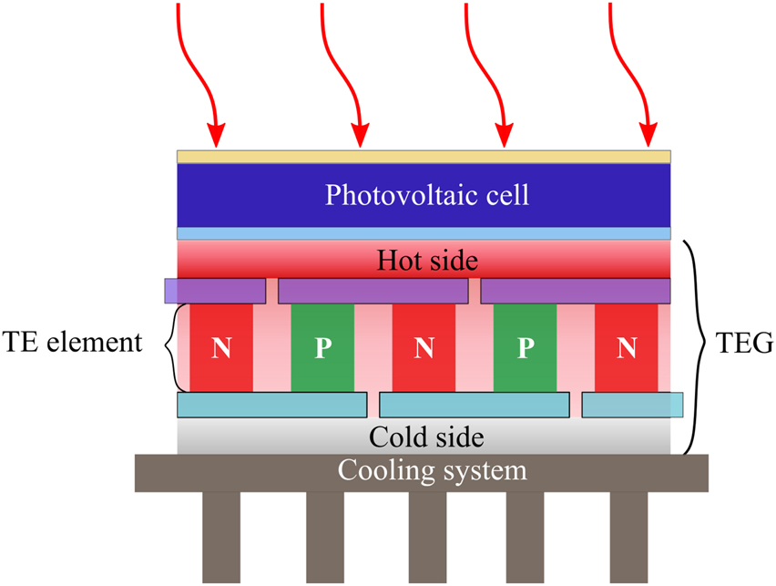
The hybrid PV-TE system.
The same assumptions were made in this study as in our previous work, except for the cold side temperature of the TEG, which is not maintained at the ambient temperature, but it is allowed to reach lower temperature values thanks to the cooling system. In this analysis, the following assumptions have been made:
The temperature of the PV cell is uniform and identical to the hot side temperature of the TE, Tcell = TH;
The heat transfer is one-dimensional, so the lateral heat transfer is neglected;
The physical properties of the TE material are constant and temperature-independent;
The geometrical properties of the thermoelectric element are identical;
The thermal and electrical contact resistances are negligible;
The electrical power generated by the hybrid system (PPVTE) corresponds to the sum of the PV (PPV) and TE (PTE) power and is expressed by:
The electrical power generated by the PV cell (PPV) is given using the expression in the following equation (Skoplaki and Palyvos 2009):
where τ is the transmissivity of the glass cover, PS is the solar radiation and APV is the area of the PV cell. The efficiency of the PV cell ηPV is expressed as follows:
where ηPV, 298K is the efficiency of the PV cell at 298 K (25 °C) and β is the temperature coefficient. The temperature coefficient β plays an important role in the degradation of the PV cell performance with increasing temperature. For this reason, the TEG is integrated next to the PV cell, to compensate and mitigate this efficiency degradation.
For the electrical power across the TEG, the governing equation is given in terms of the temperature difference between the hot side TH and the cold side TC, the number of thermocouples N, the cross-sectional area ATE, the length lTE, the Seebeck coefficient S and the electrical resistivity ρ of the TE leg (Gao 2013):
The main contribution of our previous study is the critical temperature difference across the TEG that guarantees the same power of the hybrid system as that of the PV cell alone at 298 K. At first, we need to introduce the ratio of the hybrid system to the PV cell alone at 298 K:
Using Eqs. (3), (4), and (2) lead to:
Then we can derive the critical temperature difference using the previous equations for r = 1, and assuming for the moment that the cold side TC of the TEG is maintained at the ambient temperature Ta:
We can extend this formula 8 to allow the calculation of the temperature difference required for any ratio r, the new formula can be expressed as:
Now we will allow the cold side TC of the TEG to take any value, and using Eq. (6) we derive a new equation for the ratio r, as a function of the hot and the cold side temperature of the TEG:
Consequently, we can evaluate the hybrid system performance and compare it with PV cell alone for any ratio “r” and under any cold side temperature. So far, the theoretical model serves to describe the behavior of the hybrid system and to predict the minimal working condition from which the performance of the hybrid system exceeds that of the PV cell alone at 298 K.
In the next section, the theoretical model is used to evaluate the performance of the hybrid system with three different PV cells and a TEG based on Bismuth Tin (BiSn). The characteristics of the PV-TE hybrid system are given in Tables 1 and 2.
Characteristics of the PV cells integrated in the hybrid system.
| Type of the PV cell | η PV, 298K (%) | β (%K−1) | References |
|---|---|---|---|
| a-Si | 10.2 | 0.13 | Green et al. (2016), Virtuani et al. (2010) |
| Poly-Si | 19.5 | 0.536 | Green et al. (2016), Yamamoto et al. (2000) |
| Mono-Si | 25.6 | 0.41 | Green et al. (2016), Dubey et al. (2013) |
| Parameters | Symbol | Value | |
| Area of the PV cell | A PV | 6.5 cm × 5.5 cm | |
| Solar radiation | P S | 1000 W/m−2 | |
| Transmissivity of the glass | τ | 0.95 |
Characteristics of the thermo-electric material (BiSn) (Yin et al. 2017).
| Parameters | Symbol | Value |
|---|---|---|
| Seebeck coefficient | S | 230 μV/K |
| Electrical resistivity | Ρ | 7.23 × 10⁻⁶ Ωm |
| Thermal conductivity | κ | 1.82 W/m K |
| Cross-sectional area of TE leg | A TE | 0.87 mm2 |
| Length of TE leg | l TE | 1.6 mm |
| Number of thermocouples | N | 127 |
Simulation results
To evaluate the performance of the PV-TE hybrid system, the power of the hybrid system (PPVTE) and its components (PPV) and (PTE) against the temperature difference ΔT across the TEG is presented in Figure 2, assuming that the cold side temperature of the TEG is maintained at the ambient temperature and equal to 298 K. As depicted, the power of the PV cell decreases with increasing ΔT. In contrast, the power of the TEG improves and contributes more and more to the hybrid system as ΔT increases. This opposite behavior of the components of the hybrid system is reflected in the overall power of the hybrid system, where we can see at the first phase, the power of the hybrid system is dominated by the PV cell at smaller ΔT leading to a degradation in the overall power. As the temperature rises, the power of the hybrid system reaches a minimum and starts improving, approaching the second phase where the TEG takes over and mitigates the degradation in the PV cell power.

The power of the PV-TE hybrid system, the PV cell and the TEG as a function of the temperature difference across the TEG, (a) a-Si-TE system, (b) poly-Si-TE system and (c) mono-Si-TE system.
The performance of the PV-TE hybrid system is greatly influenced by the product of the temperature coefficient and the efficiency of the PV cell. This product is equal to 1.32, 10.45 and 10.49%K−1 for the a-Si, poly-Si, and mono-Si PV cell, respectively. As we go from a-Si to mono-Si PV cell, the product increase, consequently, the critical temperature difference becomes increasingly larger. In short, the critical temperature difference across the TEG needed to overcome the PV cell alone is 1.78, 14, and 14.1 K for the a-Si, poly-Si, and mono-Si-TE hybrid system, respectively. It is apparent that the minimal critical temperature difference is attributed to the a-Si PV cell, due to its relatively small product of the temperature coefficient and the efficiency of the PV cell of 1.32%K−1.
The contribution of the TEG power to the hybrid system is also presented on the right axis (PTE/PPVTE). As can be seen from Figure 2, the contribution of the TEG is always increasing with increasing ΔT as expected, and the amount of contribution varies disproportionately with the efficiency of the PV cell used. At the critical temperature difference, the contribution of the TEG is 0.3, 5.7, and 7.8% for the a-Si, mono-Si, and poly-Si-TE hybrid systems, respectively. We can see that the higher contribution of the TEG at the critical temperature difference is attributed to the poly-Si-TE hybrid system due to its high-temperature coefficient, which causes a rapid degradation in the PV cell power, consequently, more TEG contribution is needed to attenuate the effect of the performance degradation of the PV cell.
The evolution of the ratio “r” with increasing ΔT is indicated in Figure 3. This ratio has the same critical temperature difference mentioned previously. The results show that for a given “r” higher than one, the temperature difference needed across the TEG increases proportionally with the product of the temperature coefficient and the efficiency of the PV cell. “r” curve for the a-Si increases rapidly due to its relatively small temperature coefficient and efficiency. On the other hand, the product of the temperature coefficient and the efficiency for the poly-Si and the mono-Si PV cell is almost the same, therefore, their “r” curves have more or less the same general shape. For a given ratio “r”, in particular for an increase in the PV-TE hybrid system efficiency by 10%, the temperature difference across the TEG needed is 12.5, 24.5, and 27 K for the a-Si, poly-Si, and mono-Si-TE hybrid system, respectively. In short, the selected PV cell for the hybrid system influences greatly the behavior of the ratio “r” with increasing temperature.

The ratio r as a function of the temperature difference across the TE for the PV-TE hybrid systems.
Figure 4 shows the general case of different hot and cold sides temperatures of the TEG and the corresponding ratio “r”, the variation of the cold side temperature will allow for the integration of a cooling system. The figure indicates the influence of the cold side temperature as it decreases, leading to an increase in the ratio “r” for a given hot side temperature. As a result, we can achieve a higher ratio “r” with a smaller hot side temperature, hence, enhancing the performance of the hybrid system. As can be seen also from this figure, the curves become less dense as we go from a-Si to mono-Si due to the influence of the temperature coefficient and the efficiency of the PV cell as discussed previously. Accordingly, we can achieve a higher ratio “r” with a slight change in the cold side temperature, using PV cells with a small temperature coefficient and efficiency; in this case, the a-Si PV cell is the best choice.

The ratio r as a function of the hot side and cold side temperatures of the TEG.
Experimental results
The integrated PV-TE hybrid system consists of a Polycrystalline PV cell from Uxcell in size of 110 mm by 69 mm. Three commercial Bismuth Tin TEGs (TEC1-1270) connected in series were used, with a heat sink attached to the cold side of the TEG in order to dissipate heat and maintain the cold side at a relatively low temperature. All the contact surfaces in the hybrid system are covered with thermal grease to ensure good thermal contact. The experimental setup of the PV-TE hybrid system is illustrated in Figure 5(a). Hot side temperature, cold side temperature, and ambient temperature were measured using thermocouple sensors. For the hot side temperature, the thermocouple sensor was inserted between the PV cell and the TEG. As well, voltmeter and ammeter sensors were used to measure the power of the hybrid system. The sensors were connected afterward to an open-source Arduino microcontroller board, in order to measure the response from each sensor consistently and with good accuracy and precision as shown in Figure 5(b). The experiment was carried out under simulated sunlight using a sun simulator displayed in Figure 5(c), moreover, a pyranometer is employed to measure the solar radiation and keep it at 700 W/m−2.

The experimental setup.
(a) The PV-TE hybrid system. (b) Block diagram of the experimental setup. (c) Sunlight simulator.
The PV cell will convert a part of the solar energy into electricity and the remaining is dissipated as heat, which causes the working temperature of the PV cell to increase. The TEG will absorb this heat afterward and convert it into electricity, improving the performance of the hybrid system accordingly. Figure 6 represents an IR image of the PV cell showing a nearly smooth distribution of temperature, ensuring the validity of the assumption that the PV cell temperature is homogeneous and equal to the hot side temperature of the TEG.

IR image of the PV cell.
The experimental results were measured with some uncertainty. The temperature was measured using thermocouple sensors with an uncertainty ±0.01 °C. The accuracy of the voltmeter and ammeter sensors is ±2% of the measured value. Consequently, the percentage error for the power is:
where δP, δV and δI are errors in P, V and I respectively. The uncertainty in power P is then 4% of the calculated value.
Figure 7(a) illustrates the experimental and theoretical output power of the PV cell and the TEG. As indicated, the experimental curves demonstrate the same tendency compared to the analytical curves. The experimental data was extrapolated further in Figure 7(b), allowing us to draw the overall power of the hybrid system (PHPVTE-exp) and the contribution of the TEG to the hybrid system (PTE-exp/PHPVTE-exp). The effect of the temperature on the performance of the PV cell is clearly demonstrated in the figure, where increasing the temperature from 26 to 40 °C causes a linear degradation in the output power of the PV cell by 7% as expected. Simultaneously, the output power of the TEG grows as the temperature difference increases exhibiting the Seebeck effect. The overall power of the hybrid system drops at the beginning following the behavior of the PV cell, however, after reaching a minimum value at 30 °C the overall power takes off and exceeds the PV cell alone at 25 °C for a temperature difference across the TEG of 6.5 °C. On the other hand, the contribution of the TEG to the hybrid system goes from 0 to 16% for a temperature difference across the TEG of 14 °C, as a result, mitigating the degradation in the PV cell power and enhancing the performance of the hybrid system.

The power of the hybrid system.
(a) Experimental versus Theoretical power of the PV cell and the TEG. (b) The experimental power of the PV-TE hybrid system extrapolated.
Figure 8(a) shows an increase in the overall power of the hybrid system at higher temperatures starting from a hot side temperature of 33 °C. However, there is a trade-off between the contribution of the PV cell and the TEG. As the temperature increases, the output power of the PV cell decreases, and the output power of the TEG increases thereby compensating for the hybrid system’s overall power. Figure 8(b) illustrates the ratio “r” as ΔT increases. It can be observed that the ratio “r” drops to a minimum value ΔT of 3.5 C, at this point, the negative change in the power of the PV cell is equal to the positive change in the power of the TEG. Afterward, the increase of the positive change in the power of the TEG with increasing ΔT is accompanied by a rise in the ratio “r”, reaching consequently the critical temperature difference ΔT at 7 C.

Extrapolated experimental results and simulation results. (a) The power. (b) The ratio r.
As can be observed, the theoretical model matches more or less the experimental data, indicating that the theoretical model may provide a good estimate of the performance of the hybrid system. However, there are slight differences between the experimental data and the theoretical model of the power of the TEG that can be attributed to the TE material dependency on temperature which is neglected in this model. Moreover, at high temperatures the deviation is apparent, the simulation curves diverge from the experimental curves as a result of extrapolation inaccuracies.
In short, the model developed previously can predict practically the critical temperature difference, particularly for temperature ranges corresponding to the selected TE properties. Moreover, adding more TEGs to the hybrid system give promising results by attaining the minimal working condition at moderately small temperatures.
Conclusions
In this study, we have extended our previous model to operate under any cold side temperature of the TEG, allowing the integration of a cooling system. The extended theoretical model predicts the minimal working condition, which is the temperature difference across the TEG from which the hybrid system efficiency will exceed that of the PV cell alone at 298 K. The results reveal that the a-Si PV cell with the small product of the temperature coefficient and the efficiency reaches the minimal working condition at a relatively small temperature difference across the TEG of 1.78 K. Moreover, a slight variation in the cold side temperature of the a-Si-TE system reduces notably the minimum temperature difference, enhancing consequently the performance of the hybrid system.
An experimental study was also done to confirm the output power of the hybrid system. The experimental results were satisfactory and agreed with the theoretical model. The model showed an acceptable capability to predict the performance of the hybrid system and to prove the superiority of the hybrid system to the PV cell alone at 298 K starting from the minimum temperature difference across the TEG.
This work may help in the design of the hybrid system for optimized performance. The influencing parameters, in particular, the temperature coefficient, the efficiency of the PV cell, and the cold side temperature of the TE were examined, emphasizing their effect on the behavior of the hybrid system. In addition, the expected progress in the material’s physical property of the PV cell and the TE will enhance the performance of the hybrid system, and it will be employed more in future applications.
-
Author contributions: All the authors have accepted responsibility for the entire content of this submitted manuscript and approved submission.
-
Research funding: None declared.
-
Conflict of interest statement: The authors declare no conflicts of interest regarding this article.
References
Al-Shahri, O. A., F. B. Ismail, M. Hannan, M. H. Lip, A. Q. Al-Shetwi, R. Begum, N. F. Al-Muhsen, and E. Soujeri. 2020. “Solar Photovoltaic Energy Optimization Methods, Challenges and Issues: A Comprehensive Review.” Journal of Cleaner Production 284: 125465.10.1016/j.jclepro.2020.125465Suche in Google Scholar
Chubb, D. L., and B. S. Good. 2018. “A Combined Thermophotovoltaic-Thermoelectric Energy Converter.” Solar Energy 159: 760–7, https://doi.org/10.1016/j.solener.2017.11.030.Suche in Google Scholar
Cotfas, D. T., P. A. Cotfas, D. Ciobanu, and O. M. Machidon. 2017. “Characterization of Photovoltaic–Thermoelectric–Solar Collector Hybrid Systems in Natural Sunlight Conditions.” Journal of Energy Engineering 143 (6): 04017055, https://doi.org/10.1061/(asce)ey.1943-7897.0000488.Suche in Google Scholar
Dubey, S., J. N. Sarvaiya, and B. Seshadri. 2013. “Temperature Dependent Photovoltaic (Pv) Efficiency and its Effect on Pv Production in the World—A Review.” Energy Procedia 33: 311–21, https://doi.org/10.1016/j.egypro.2013.05.072.Suche in Google Scholar
El Mliles, M., Y. El Kouari, and A. Hajjaji. 2019. “The Effect of the Temperature Difference on the Performance of Photovoltaic-Thermoelectric Hybrid Systems.” Journal of Solar Energy Engineering 141 (5): 051010, https://doi.org/10.1115/1.4043550.Suche in Google Scholar
Elavarasan, R. M., G. Shafiullah, S. Padmanaban, N. M. Kumar, A. Annam, A. M. Vetrichelvan, L. Mihet-Popa, and J. B. Holm-Nielsen. 2020. “A Comprehensive Review on Renewable Energy Development, Challenges, and Policies of Leading Indian States with an International Perspective.” IEEE Access 8: 74432–57, https://doi.org/10.1109/access.2020.2988011.Suche in Google Scholar
Gao, M. 2013. “Thermoelectric Module Design Under a Given Thermal Input: Theory and Example.” Journal of Electronic Materials 42 (7): 2239–42, https://doi.org/10.1007/s11664-013-2514-2.Suche in Google Scholar
Green, M. A., K. Emery, Y. Hishikawa, W. Warta, and E. D. Dunlop. 2016. “Solar Cell Efficiency Tables (Version 48).” Progress in Photovoltaics: Research and Applications 24: 905–13, https://doi.org/10.1002/pip.2788.Suche in Google Scholar
Gu, W., T. Ma, A. Song, M. Li, and L. Shen. 2019. “Mathematical Modelling and Performance Evaluation of a Hybrid Photovoltaic-Thermoelectric System.” Energy Conversion and Management 198: 111800, https://doi.org/10.1016/j.enconman.2019.111800.Suche in Google Scholar
Indira, S. S., C. A. Vaithilingam, K.-K. Chong, R. Saidur, M. Faizal, S. Abubakar, and S. Paiman. 2020. “A Review on Various Configurations of Hybrid Concentrator Photovoltaic and Thermoelectric Generator System.” Solar Energy 201: 122–48, https://doi.org/10.1016/j.solener.2020.02.090.Suche in Google Scholar
Karthick, K., S. Suresh, M. M. M. Hussain, H. M. Ali, and C. S. Kumar. 2019. “Evaluation of Solar Thermal System Configurations for Thermoelectric Generator Applications: A Critical Review.” Solar Energy 188: 111–42, https://doi.org/10.1016/j.solener.2019.05.075.Suche in Google Scholar
Kohan, H. F., F. Lotfipour, and M. Eslami. 2018. “Numerical Simulation of a Photovoltaic Thermoelectric Hybrid Power Generation System.” Solar Energy 174: 537–48, https://doi.org/10.1016/j.solener.2018.09.046.Suche in Google Scholar
Lamba, R., and S. Kaushik. 2016. “Modeling and Performance Analysis of a Concentrated Photovoltaic–Thermoelectric Hybrid Power Generation System.” Energy Conversion and Management 115: 288–98, https://doi.org/10.1016/j.enconman.2016.02.061.Suche in Google Scholar
Li, M., D. Zhong, T. Ma, A. Kazemian, and W. Gu. 2020. “Photovoltaic Thermal Module and Solar Thermal Collector Connected in Series: Energy and Exergy Analysis.” Energy Conversion and Management 206: 112479, https://doi.org/10.1016/j.enconman.2020.112479.Suche in Google Scholar
Liao, T., B. Lin, and Z. Yang. 2014. “Performance Characteristics of a Low Concentrated Photovoltaic–Thermoelectric Hybrid Power Generation Device.” International Journal of Thermal Sciences 77: 158–64, https://doi.org/10.1016/j.ijthermalsci.2013.10.013.Suche in Google Scholar
Marandi, O. F., M. Ameri, and B. Adelshahian. 2018. “The Experimental Investigation of a Hybrid Photovoltaic-Thermoelectric Power Generator Solar Cavity-Receiver.” Solar Energy 161: 38–46, https://doi.org/10.1016/j.solener.2017.12.039.Suche in Google Scholar
Othman, M., B. Yatim, K. Sopian, and M. Bakar. 2006. “Double-pass Photovoltaic-Thermal Solar Collector.” Journal of Energy Engineering 132 (3): 121–6, https://doi.org/10.1061/(asce)0733-9402(2006)132:3(121).10.1061/(ASCE)0733-9402(2006)132:3(121)Suche in Google Scholar
Saidi, K., and A. Omri. 2020. “The Impact of Renewable Energy on Carbon Emissions and Economic Growth in 15 Major Renewable Energy-Consuming Countries.” Environmental Research 186: 109567, https://doi.org/10.1016/j.envres.2020.109567.Suche in Google Scholar PubMed
Skoplaki, E., and J. Palyvos. 2009. “On the Temperature Dependence of Photovoltaic Module Electrical Performance: A Review of Efficiency/power Correlations.” Solar Energy 83 (5): 614–24, https://doi.org/10.1016/j.solener.2008.10.008.Suche in Google Scholar
Virtuani, A., D. Pavanello, and G. Friesen. 2010. “Overview of Temperature Coefficients of Different Thin Film Photovoltaic Technologies.” In 25th European Photovoltaic Solar Energy Conference and Exhibition/5th World Conference on Photovoltaic Energy Conversion.Suche in Google Scholar
Wang, Y., H. Li, H. Hao, and X. Chen. 2018. “Performance Optimization of a Photovoltaic Solar Cell-Based Hybrid System.” Journal of Renewable and Sustainable Energy 10 (4): 044702, https://doi.org/10.1063/1.5028147.Suche in Google Scholar
Xu, H., F. Karimi, J. Chen, M. Yang, and S. Yu. 2018. “Experimental Investigation on a Photovoltaic Thermal Solar System with a Linear Fresnel Lens.” Journal of Energy Engineering 144 (3): 04018012, https://doi.org/10.1061/(asce)ey.1943-7897.0000516.Suche in Google Scholar
Yamamoto, K., M. Yoshimi, Y. Tawada, Y. Okamoto, and A. Nakajima. 2000. “Thin Film si Solar Cell Fabricated at Low Temperature.” Journal of Non-Crystalline Solids 266: 1082–7, https://doi.org/10.1016/s0022-3093(99)00907-2.Suche in Google Scholar
Yin, E., Q. Li, and Y. Xuan. 2017. “One-Day Performance Evaluation of Photovoltaic-Thermoelectric Hybrid System.” Energy 143: 337–46, https://doi.org/10.1016/j.enconman.2017.04.004.Suche in Google Scholar
Zhang, J., and Y. Xuan. 2019. “An Integrated Design of the Photovoltaic-Thermoelectric Hybrid System.” Solar Energy 177: 293–8, https://doi.org/10.1016/j.solener.2018.11.012.Suche in Google Scholar
Zhang, J., H. Zhai, Z. Wu, Y. Wang, and H. Xie. 2020. “Experimental Investigation of Novel Integrated Photovoltaic-Thermoelectric Hybrid Devices with Enhanced Performance.” Solar Energy Materials and Solar Cells 215: 110666, https://doi.org/10.1016/j.solmat.2020.110666.Suche in Google Scholar
© 2022 Walter de Gruyter GmbH, Berlin/Boston
Artikel in diesem Heft
- Frontmatter
- Review
- A comprehensive review on electric vehicles: charging and control techniques, electric vehicle-grid integration
- Research Articles
- Evaluation of parameters influencing the performance of photovoltaic-thermoelectric (PV-TE) hybrid system
- Dispatchable power supply from beam down solar point concentrator coupled to thermal energy storage and a Stirling engine
- Modelling, design and parametric analysis of a levitation based energy harvester
- Performance optimization of flywheel using experimental design approach
- Assessment and optimization of photovoltaic systems at the University Ibn Tofail according to the new law on renewable energy in Morocco using HOMER Pro
- Optimizing hybrid power system at highest sustainability
- Preparation of Na2HPO4⋅12H2O-based composite PCM and its application in air insulated box
- The efficiency of linear electromagnetic vibration-based energy harvester at resistive, capacitive and inductive loads
- A numerical investigation of optimum angles for solar energy receivers in the eastern part of Algeria
- Experimental investigation of soiling effects on the photovoltaic modules energy generation
- Frequency domain analysis of a piezoelectric energy harvester with impedance matching network