Investigation of mechanical performances of composite bolted joints with local reinforcements
-
Jifeng Zhang
 ,
Qiang Xie
,
Qiang Xie

Abstract
Four different local reinforcement schemes used in composite bolted joints were studied. In numerical study, a set of 3-D failure criteria was used and the progressive failure analysis was implemented via user-defined subroutine vectorized user-material (VUMAT), which was programmed by the commercial finite element (FE) software ABAQUS. In the experiment, test specimens were manufactured with different local reinforcement schemes, and the mechanical performances of these specimens were tested under tensile loads. Failure modes of these specimens were observed and mechanical performances of test specimens with local reinforcement were studied. It was found that the numerical results agreed well with the experiment. It was also found that local reinforcement schemes influenced the mechanical performances of bolted joints obviously and that the tensile strength of composite bolted joints could be improved significantly by burying laminate slices.
1. Introduction
Modern aircraft structures require extensive use of advanced fiber-reinforced polymer matrix composites in order to reduce the weight and to improve aircraft performances. Joint technology is very important in composite structure design. Among a large number of joint methods existing in composite structure design, the bolted joint is a very common method for assembling composite primary components. Efficient bolted joint designs can minimize the weight of composite structures. Poorly designed joints could thus detract significantly from the weight advantage of composites over metals. A lot of studies on bolted joints focused on discovering the failure mode and the effect of various bolted parameters on joint strength [1], [2], [3], [4]. Research methods include experiment and simulation. In recent years, researchers have developed various joint schemes to improve mechanical performances of bolted joints. Ucsnik et al. [5] welded small spikes onto metal surfaces to improve the joint performance between steel and carbon fiber-reinforced polymer laminates. McCarthy et al. [6] proposed a joint scheme for the multi-bolt joint of carbon-epoxy aircraft fuselages. However, bolted joints have disadvantages compared to adhesive joints, as bolt holes cause fiber discontinuousness and stress concentration, which reduce the total efficiency of joint constructions. Furthermore, machining bolt hole usually induces defects into composite structures [7]. Researchers have taken many methods to solve the problem. Kolesnikov et al. [8] embedded thin titanium layers into composite laminates, which resulted in a considerable improvement in the structural efficiency of bolted joints. Li et al. [9] investigated the effect of z-pins on the bearing property and damage tolerance of composite bolted joints. Bouchard et al. [10] proposed a novel insert scheme that can improve the performance of thick-lap bolted composite joints.
In the paper, we studied four different local reinforcement schemes used in composite laminates bolted joints. These local reinforcement schemes include outer patches with composite laminate slices, buried rigid foam slices, buried aluminum alloy slices and buried patches with composite slices. In the experiment, these test specimens with different local reinforcement schemes were manufactured and their tensile performances were tested. In the numerical study, we programmed the subroutine VUMAT by ABAQUS (Dassault Systemes, Paris, France) and simulated the 3-D progressive failure process of test specimens.
2. Specimen fabrication and test
Five groups of test specimens were manufactured, as shown in Figure 1, and there were three specimens per group. Among them, Group A was made of glass fiber-reinforced plastic (GFRP) without local reinforcement, in order to compare with other groups. The other four groups were manufactured with different local reinforcement schemes. All these test specimens were manufactured by the vacuum-assisted resin injection (VARI) process. Serial numbers of these groups are shown in Table 1. These GFRP composite laminates were made from unidirectional glass fabric (Weihai Guangwei Composites Co., Ltd, Weihai, Shandong Province, China) having a weight of 200 g/m2 and vinyl ester resin (Shanghai Shangde Co., Ltd, Shanghai, China). The stacking sequence of these laminates was [0/45/-45/90/0]s. Each ply thickness for these laminates was nominally 0.22 mm yielding a nominal laminate thickness of 2.2 mm. Groups B and E were reinforced by outer and buried GFRP laminate slices, respectively (described in Figure 2), and Groups C and D were reinforced by PVC rigid foam slices (Zhejiang Wang Yang Polymer Materials Co., Ltd, Wenzhou, Zhejiang Province, China) and aluminum alloy slices (Southwest Aluminum Corporation Co., Ltd, Chongqing, China), respectively. The geometrical details of local reinforcement are described in Figure 2. The properties of orthotropic lamina are listed in Table 2. In the table, the subscript “1” indicates the direction along fibers, whereas the subscript “2” indicates the direction normal to fibers. XTand XC are defined as the tensile strength and compression strength along fibers, respectively, as well YT and YC are defined as the tensile strength and compression strength normal to fibers, respectively. The properties of PVC foam are specified by tensile elastic modulus ET=0.3 GPa, compression elastic modulus EC=0.6 GPa, the tensile strength XT=8.0 MPa, compression strength XC=6.0 MPa and Poisson’s ratio v=0.33. Properties of aluminum alloy slices buried in group D are as follows: elastic modulus E=53.8 GPa, Poisson’s ratio v=0.33, yield strength σ=390 MPa and the break elongation δ=21%. In the manufacture process of these specimens with buried reinforcement, the reinforcement slices were buried between the fifth and sixth plies of laminates. Buried aluminum alloy slices in group D were pre-treated by phosphoric acid anodizing in order to improve the glue performance between aluminum alloy slices and GFRP laminates. The method of phosphoric acid anodizing referred to the People’s Republic of China Aviation Industry standard HB/Z197-91.
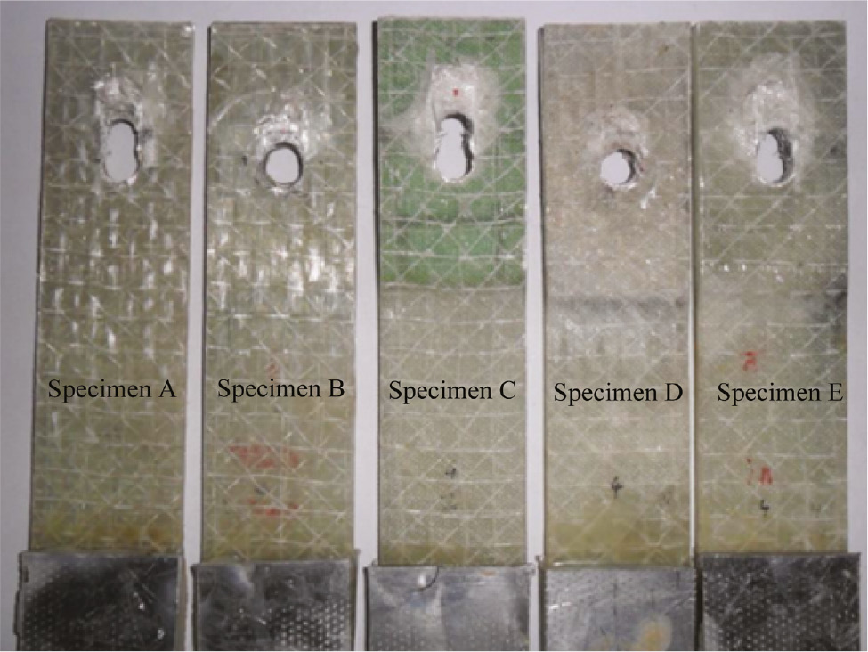
Photos of test specimens.
Serial number of specimens.
| Specimen | Local reinforcement |
|---|---|
| A | – |
| B | Outer patches with laminate slices |
| C | Buried rigid foam slices |
| D | Buried aluminum alloy slices |
| E | Buried patches with laminate slices |
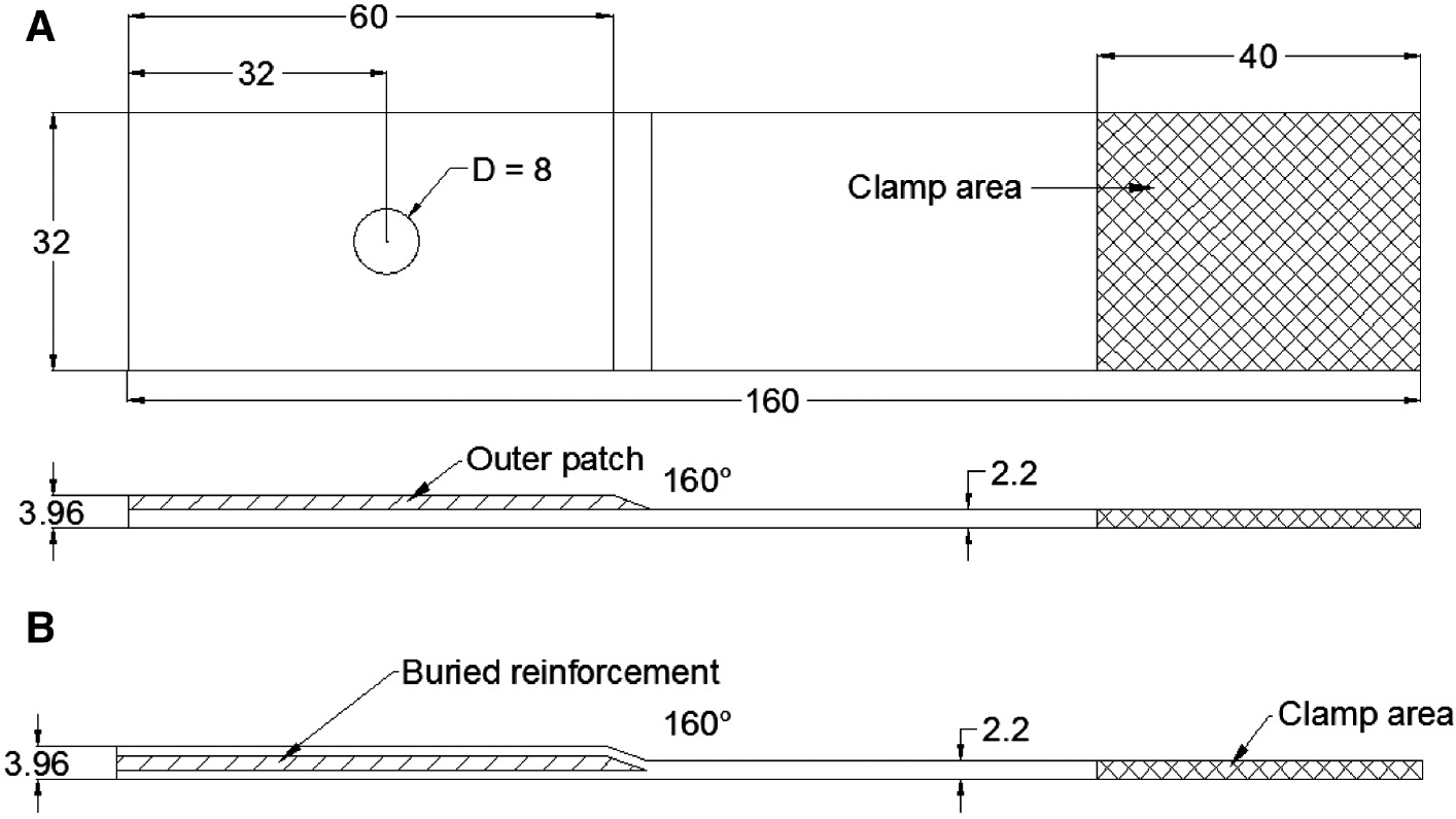
Local reinforcement sketch and geometrical sizes of test specimens. (A) Outer reinforcement plies (dimensions: mm). (B) Buried reinforcement slices (dimensions: mm).
Properties of GFRP orthotropic lamina.
| E1 | E2=E3 | G12=G13 | G23 | ν12=ν13 | ν23 |
|---|---|---|---|---|---|
| 20.0 GPa | 6.45 GPa | 3.55 GPa | 1.52 GPa | 0.3 | 0.5 |
| XT | XC | YT | YC | S12=S13 | S23 |
| 560.0 MPa | 450.0 MPa | 10.4 MPa | 106.0 MPa | 13.7 MPa | 6.0 MPa |
The fiber orientations were measured from the loading direction. The fabrication and machining process of these test specimens and the procedure for determining these material properties were explained in [11], [12]. Based on these studies, two geometrical parameters, distance E from the free edge of specimen to the diameter D of bolt hole ratio (E/D) and the width W of the specimen to the diameter D of bolt holes ratios (W/D), were assigned a value of 4 in order to avoid low strength failure modes, such as shear out and cleavage failure modes.
The uniaxial tensile test was performed on Zwick/Roell servo-mechanical testing machine (Zwick/Roell Group, Worms, Germany) with the maximal 20 kN force. In order to avoid the tensile eccentric effect, an L-type test clamp was designed. The experiment setup and the L-type clamp are shown in Figure 3. Based on previous research results [11], [12], the bolt torque was assigned to 4 N.m. The load was applied on the end of the specimen with a constant speed of 2.0 mm per minute until test specimens collapsed. So the traction process was considered as a quasi-static problem in the following numerical study. The bolt and the L-type clamp were made of high-strength steel, with a yield strength of 900 MPa. The bolt and the L-type clamp did not have plastic deform action in the tensile process.
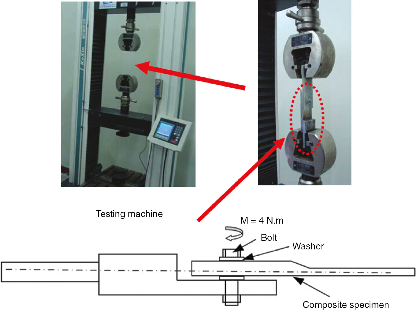
The experimental setup and the L-type clamp for bolted-joint test.
3. Numerical study
3.1 Failure criteria
Most accurate and general models to predict the failure process and ultimate strength of composite structures are based on the implementation of constitutive models developed in the context of continuum damage mechanics in finite element (FE) models. The development of a reliable FE model to predict the failure of bolted composite joints requires the implementation of reliable failure criteria. Hashin’s criteria have widely been used to predict bearing failure in double-lap and single-lap bolted joints. Hühne et al. [13] have proved the influence of out-of-plane stresses on the bearing strength of bolted joints, and however Hashin’s criteria could not be used to analyze non-linear shear stress-strain relationship. Olmedo and Santiuste [14] developed a set of failure criteria to predict the bearing strength of bolted composite joints, which consider both out-of-plane stresses and non-linear shear stress-strain relationship, listed in Table 3. Zhou et al. [15], [16] also proposed a non-linear stress-strain relationship in the context of continuum damage modeling. In the work, the Olmedo failure criteria were used.
3.2 Numerical model
As these specimens were symmetrical along the X-Z plane, we focused our interest in a half-part. The 1/2 numerical model was developed to describe the whole joint specimen. The model included laminates, bolts and washers. Contacts were assigned between these parts. The FE model was meshed and local parts were refined, as shown in Figure 4. The properties of orthotropic lamina and other materials have been described in the Section 2.
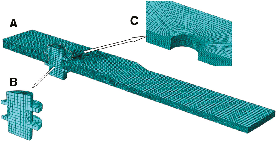
FE model mesh of bolted joints with local reinforcement. (A) 1/2 model (B) bolt and washers (C) mesh detail around hole.
In order to simulate the delamination between laminates and reinforcement slices, cohesive elements of type COH3D8 were employed, which had eight nodes and four integration points. A bilinear cohesive law was used, which had two parameters, the cohesive strength (Tm, Ts) and the energy release GIC. It is difficult to test these parameters of the interface between laminates and reinforcement slices directly, because they vary gradiently. However, we could obtain engineering parameters (or equivalent parameters) according to experimental results. The method was adapted from [11], [14] and these engineering parameters were proposed as follows:
3.3 Boundary conditions and simulation procedure
According to experiments, clamp boundary conditions were applied on one end of the model, and displacements were applied on the other end. As the bolt torque had contact problems, a friction surface was assigned between the laminates and the bolt washer. The friction coefficient was specified as 0.114 [14]. Forces along the normal plane were applied on the bolt to simulate the pre-tension condition. The ABAQUS software could adjust the length of the pre-tension section and achieved a prescribed amount of pre-tension. The relation between the torque and the normal force is described as follows:
where τ is the applied torque, d is the bolt diameter, k is the torque coefficient specified as 0.2 [17] and D is the washer diameter. Then, the bolt force Fbolt is given as:
ABAQUS/Standard can apply the bolt force Fbolt by the “PRE-TENSION SECTION” block, but ABAQUS/Explicit does not have the function. So we used a normal displacement to simulate the bolt force. In the process, an initial displacement W0 was applied and was conducted to contact pressure P0. Then, we assumed the displacement W to be proportional to the contact pressure P and deduced W=W0×P/P0. This process includes two steps: In the first step the displacement W along the z-axis was applied on the bolt nut and the end displacement of specimen was fixed. In the second step, the displacement along the z-axis remained constant and the displacement W along the x-axis was applied to free the constraint of specimen end. In order to avoid the loading step being too fast and affecting the solving convergence, we adopted “Smooth” function in ABAQUS/Explicit. The loading step was 0.001 s and the loading curve is shown in Figure 5.
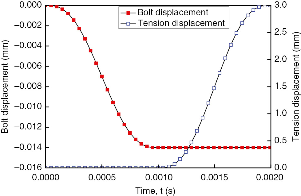
“Smooth” application of tensile displacement.
During the process of the tensile test, the displacement was applied with a constant speed of 2 mm/min; hence, this process could be treated as a quasi-static problem. A progressive failure model was also developed by ABAQUS/Explicit. In the process, user subroutine VUMAT was used to simulate the mechanical constitutive behavior of test specimens, as shown in Figure 6. When the analysis started, the stress was calculated from preset displacement and its increase. Then, the stress was called into subroutine to evaluate the Olmedo failure criteria. Once the failure criteria were satisfied, the state variables were updated and material stiffness was reduced according to Table 4 [14]. Damage stiffness matrix would be re-calculated and new element stress would be calculated by new stiffness matrix. When material properties degraded at a point, the load was re-distributed to other points, which would then fail themselves. It was therefore necessary to iterate at the same load level, when material properties changed to determine if other material points undergo failure.
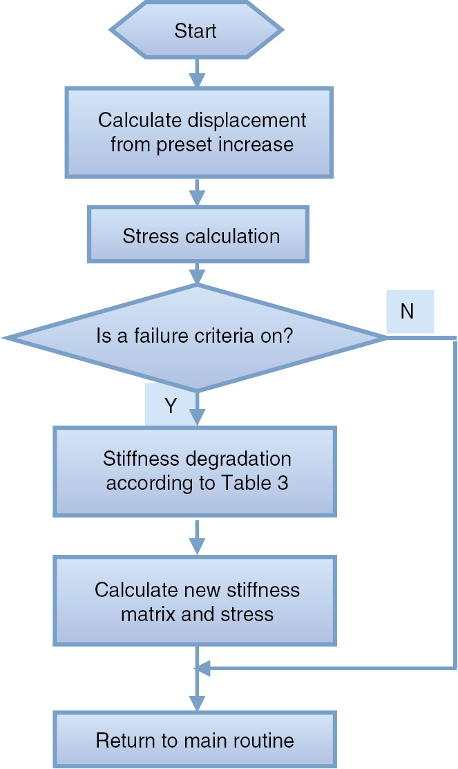
Flow chart of user subroutine VUMAT.
The Olmedo failure criteria used in the simulation.
| Failure mode | Olmedo failure criteria |
|---|---|
| Fiber tension (σ11≥0) | |
| Fiber compression (σ11<0) | |
| Matrix tension (σ22≥0) | |
| Matrix compression (σ22<0) | |
| Delamination in tension (σ33≥0) | |
| Delamination in compressive (σ33<0) | |
| Fiber–matrix shear (σ11<0) |
Stiffness degradation rule for Olmedo failure criteria [14].
| Failure mode | E11 | E22 | E33 | G12 | G13 | G23 | v12 | v13 | v23 |
|---|---|---|---|---|---|---|---|---|---|
| Fiber tensile failure | 0.14 | 0.4 | 0.4 | 0.25 | 0.25 | 0.2 | 0 | 0 | 0 |
| Fiber compression failure | 0.14 | 0.4 | 0.4 | 0.25 | 0.25 | 0.2 | 0 | 0 | 0 |
| Matrix tensile failure | – | 0.4 | 0.4 | – | – | 0.2 | 0 | 0 | 0 |
| Matrix compression failure | – | 0.4 | 0.4 | – | – | 0.2 | 0 | 0 | 0 |
| Tensile delamination failure | – | 0.4 | 0.4 | – | – | 0.2 | 0 | 0 | 0 |
| Compression delamination failure | – | 0.4 | 0.4 | – | – | 0.2 | 0 | 0 | 0 |
| Fiber–matrix shearing failure | – | – | – | 0.25 | 0.25 | – | 0 | 0 | – |
4. Results and discussion
The tensile performance of Group A–E specimens was tested, and the load-displacement curves are shown in Figure 7. From the figure, it was found that the local reinforcement improved the tensile performance of these specimens obviously, except Group C reinforced by rigid foam slices. The curve of Group D was smoother than the other groups, and we supposed that it was buried aluminum alloy slices that increased the joint elasto-plasticity. The curve of Group B fluctuated obviously and there existed a sharp “drop” in the curve. After the “drop” point in the curve, the specimen still had a certain amount of bearing capacity for a little while, which was supposed being carried by the GFRP laminates, and then the specimen failed. We supposed that the “drop” was from the detachment of outer composite patches as the tensile load increased. Furthermore, the elongation of Group C and Group E was larger than the other groups obviously. To study the phenomenon and referring to [15], [16], the stiffness spectrum of Group C and Group E was drawn as shown in Figures 8 and 9. From the figure, it was found that the elongation of Group E increased by about 100% (by a value of 2 mm) compared with Group A without reinforcement. It is an odd phenomenon that GFRP reinforcement slices are also brittle materials and could not increase the plastic behavior of these specimens; moreover, we did not find the phenomenon in simulation, either. We supposed that the phenomenon should be attributed to the sliding of bolts, for that there were twice obvious “drop”s in the stiffness spectrum of Group E before it dropped to zero, and the ultimate load of other groups was smaller than that of Group A and not enough to move the bolt and washer. In Figure 9, it was also found that the elongation of Group C increased by about 100%. The phenomenon could be attributed to the large deformation of foam and fibers. In the tensile process, the inserted foam slice would be compressed largely, which has a low elastic modulus. Then, curving fibers around the inserted foam would be straightened. This process would surely increase the elongation of test specimen.
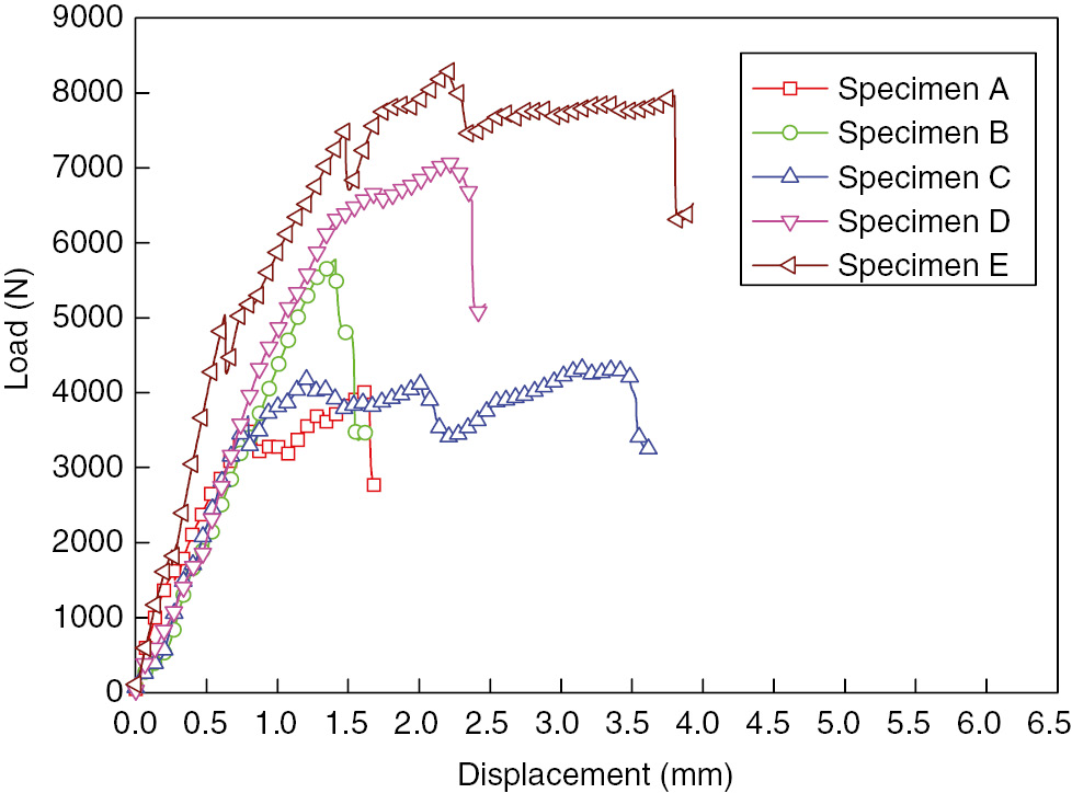
Load-displacement curves tested by experiments.
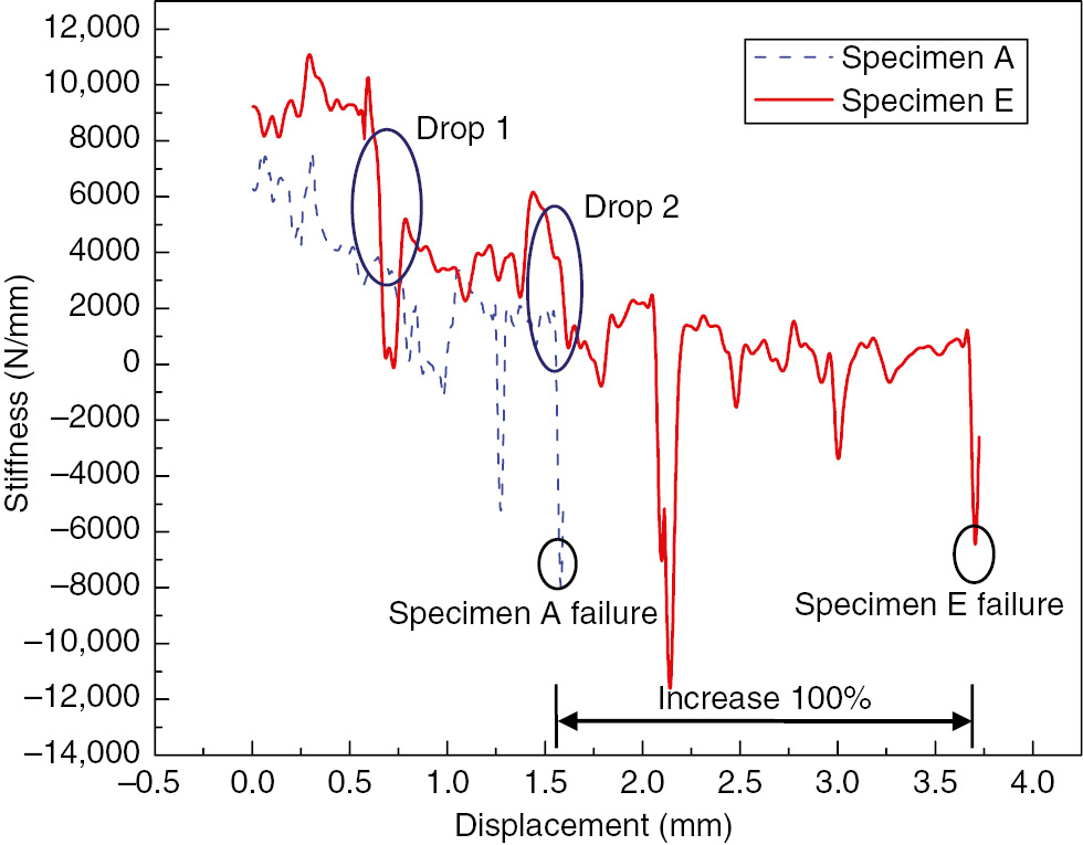
Stiffness spectrum comparison between specimen A and specimen E.
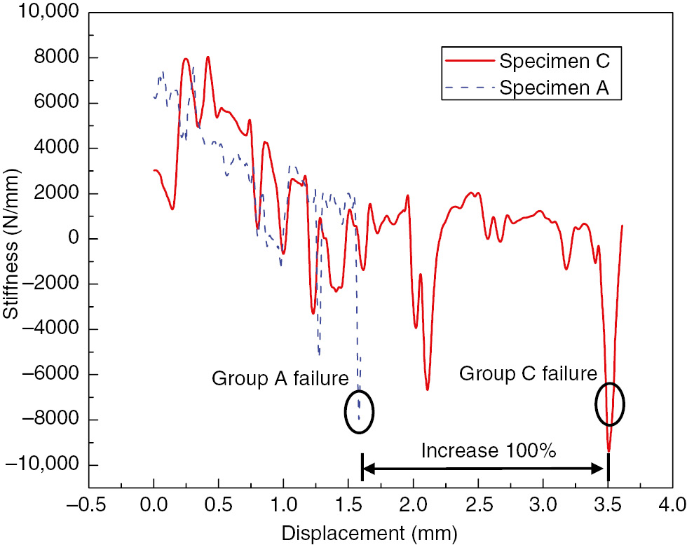
Stiffness spectrum comparison between specimen C and Specimen A.
Load-displacement curves of simulation and experimental results are shown in Figure 10. From the figure, it could be found that the simulation results agreed well with the experimental results. From the figure, we also could find that the main macroscopical failure modes were bearing failure mode and delamination between reinforced slices and GFRP laminates. Group B and Group D were mixture failure modes of bearing failure and delamination, and the other groups were bearing failure. In the simulation, the interface between GFRP laminates and reinforced slices was simulated with cohesive elements, and obvious delaminations between reinforced slices and GFRP laminates were observed in Groups B and D, as shown in Figure 11. These results agreed well with the experimental results. Another macroscopical failure mode was bearing failure, which could be caused by many microscopic failure modes, e.g. fiber compression failure, matrix compression, etc. The simulation with the Olmedo criteria could predict these microscopic failure modes. These modes included: fiber tension failure, fiber compression failure, matrix tension failure, matrix compression failure, tensile-delamination failure, compressive-delamination failure and fiber-matrix shear failure. These modes simulated with the Olmedo criteria are shown in Figure 12. These microscopic failure modes would cause macroscopical bearing failure, which was in accordance with results observed macroscopically in the experiment.
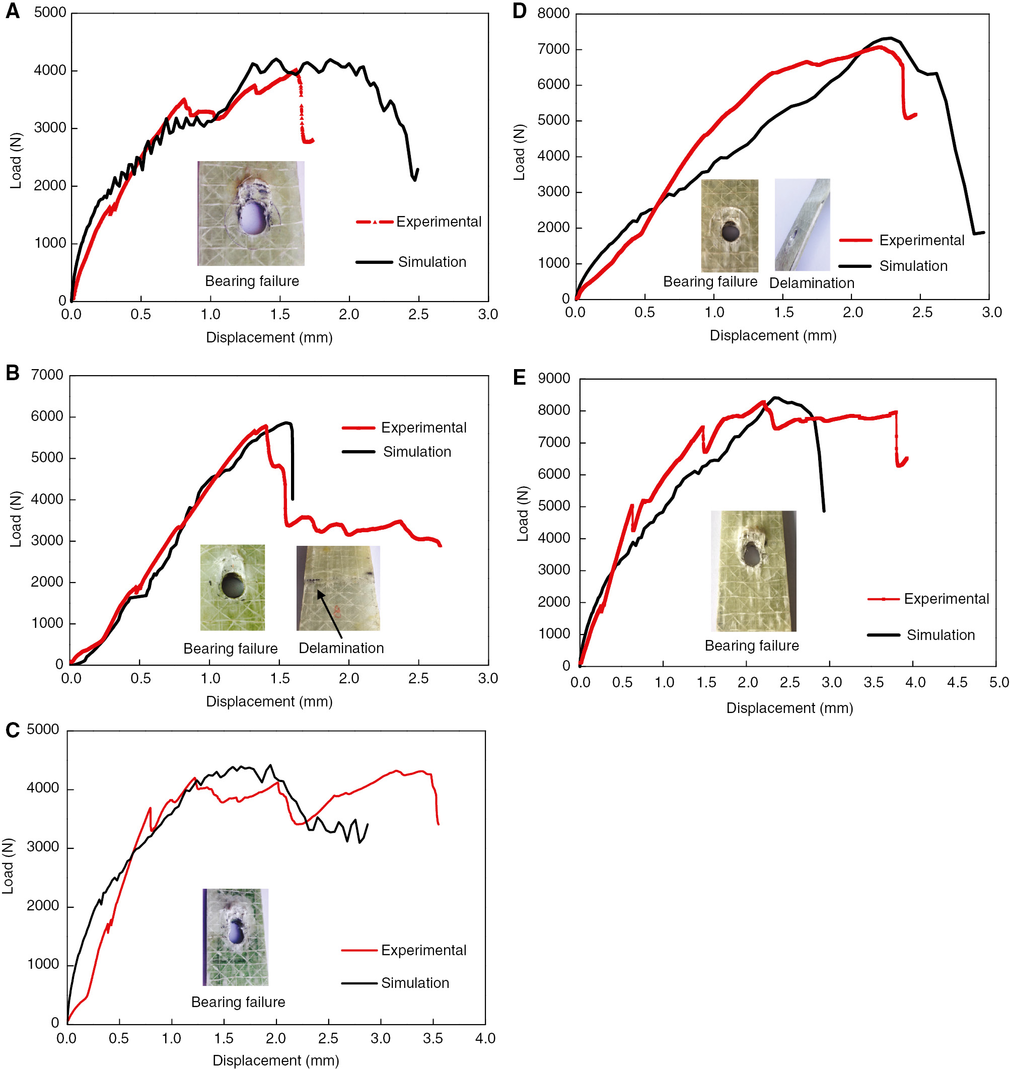
Comparisons of load-displacement curves between simulation and experimental results. (A) Specimen A, (B) specimen B, (C) specimen C, (D) specimen D and (E) specimen E.
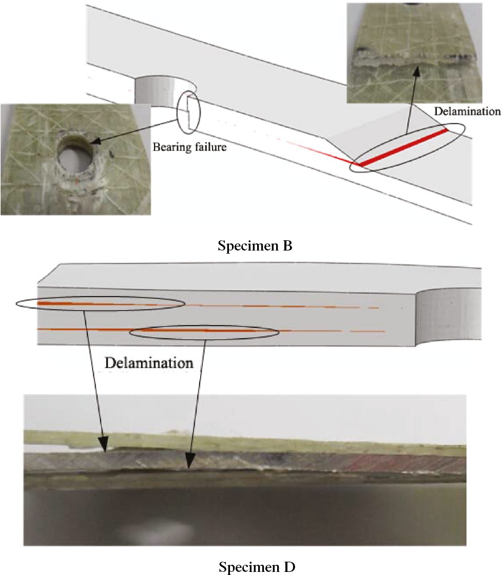
The comparison of delamination failure mode between experimental results and simulation.
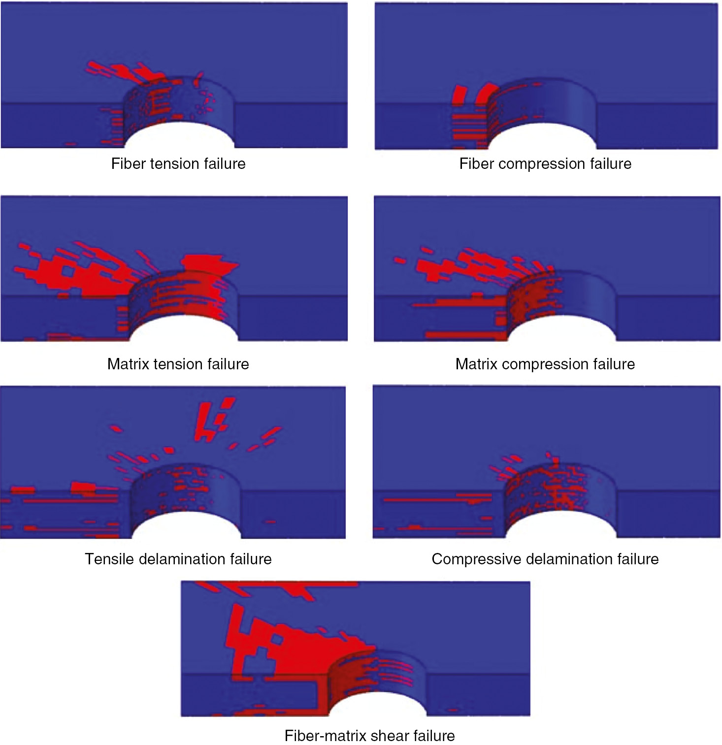
Failure modes simulated with Olmedo criteria.
The ultimate loads of these five group specimens acquired from experiment and simulation are shown in Table 5. From the table, it was found that the ultimate load of simulation agreed well with the experimental results and the max relative error was 4.81%, which was lower than 5%. Besides, we could also find that the local reinforcement increased the ultimate load of the joints obviously, except for the Group C reinforced by foam slices only with a 7.73% increase. The ultimate load of Group E reinforced by GFRP laminate slices increased about twice compared to Group A without local reinforcement. The ultimate load of Group B and Group D increased about 43.9% and 76.3%, respectively.
The ultimate load comparison between simulation and experimental results.
| Specimen | Failure load (N) | Simulation relative error % | Ultimate load increase compared with specimen A | ||
|---|---|---|---|---|---|
| Experiment | Simulation | Ultimate load increase | The % of increase | ||
| A | 4012.7 | 4205.7 | 4.81 | – | – |
| B | 5774.5 | 5862.8 | 1.53 | 1761.8 | 43.9 |
| C | 4323.0 | 4421.6 | 2.28 | 310.3 | 7.73 |
| D | 7077.0 | 7321.9 | 3.46 | 3064.3 | 76.3 |
| E | 8286.0 | 8408.2 | 1.48 | 4073.3 | 101.0 |
5. Conclusion
In this paper, four different local reinforcement schemes used in composite laminates bolted joints were studied numerically and experimentally. From the results, we concluded that:
Local reinforcement improved the tensile performance of these specimens obviously, except Group C reinforced by rigid foam slices. Reinforcement with buried aluminum alloy slices could improve not only the strength but also the elasto-plasticity behavior of the joint. The joint specimens reinforced by buried GFRP plies have the highest tensile strength, which increased twice as much as that of test specimens without reinforcement.
In the numerical study, the bolted joint traction was assumed as a quasi-static question, and a progressive failure model was developed to analyze the problem. The interface delamination between laminate and reinforcement slice was simulated with cohesive elements, which was in accordance with experimental observation. The ultimate load predicated by simulation agreed well with the experimental result, and relative error was lower than 5%. This conclusion illustrated the above numerical methods’ availability.
Funding source: National Natural Science Foundation of China
Award Identifier / Grant number: 51379048
Funding statement: This work has been funded by the National Natural Science Foundation of China (Grant No. 51379048) and the 11th Five-year Pre-research Program of Chinese Navy
Acknowledgments
This work has been funded by the National Natural Science Foundation of China (Grant No. 51379048) and the 11th Five-year Pre-research Program of Chinese Navy.
References
[1] Chang FK, Springer G, Scott R. 25th Structures, Structural Dynamics and Materials Conference, 1984, 10.2514/6.1984-917.Search in Google Scholar
[2] Hollmann K. J. Compos. Mater. 1996, 30, 358–383.10.1177/002199839603000304Search in Google Scholar
[3] Hoang TD, Herbelot C, Imad A. Eng. Fail. Anal. 2012, 4, 9–25.10.1016/j.engfailanal.2012.03.006Search in Google Scholar
[4] Gürkan A, Muzaffer T, Hasan C. Sci. Eng. Compos. Mater. 2010, 17, 199–212.10.1515/SECM.2010.17.3.199Search in Google Scholar
[5] Ucsnik S, Scheerer S, Zaremba S, Pahr DH. Compos. Part A Appl. Sci. Manuf. 2010, 41, 369–374.10.1016/j.compositesa.2009.11.003Search in Google Scholar
[6] Egan B, McCarthy CT, McCarthy MA, Gray PJ, Higgins RM. Compos. Part A Appl. Sci. Manuf. 2013, 53, 97–108.10.1016/j.compositesa.2013.05.006Search in Google Scholar
[7] Davy C, Marquis D. J. Mater. Sci. 2003, 38, 1231–1238.10.1023/A:1022861804903Search in Google Scholar
[8] Kolesnikov B, Herbeck L, Fink A. Compos. Struct. 2008, 83, 368–380.10.1016/j.compstruct.2007.05.010Search in Google Scholar
[9] Li R, Huong N, Crosky A, Mouritz AP, Kelly, Chang DP. Compos. Sci. Technol. 2009, 69, 883–889.10.1016/j.compscitech.2008.12.005Search in Google Scholar
[10] Brandon B, Bryon H, Gaetano R, Gary C. Society for Experimental Mechanics – SEM Annual Conference and Exposition on Experimental and Applied Mechanics 2010, 3, 2295–2302.Search in Google Scholar
[11] Xie YG. Strength and load distribution investigation of mechanically fastened joints of composite laminates (Master degree thesis). Harbin Engineering University, 2013.Search in Google Scholar
[12] Wang ZQ, Zhou S, Zhang JF, Wu XD, Zhou LM. Mater. Des. 2012, 27, 582–588.10.1016/j.matdes.2011.08.039Search in Google Scholar
[13] Hühne C, Zerbst AK, Kuhlmann G, Steenbock C, Rolfes R. Compos. Struct. 2010, 92, 189–200.10.1016/j.compstruct.2009.05.011Search in Google Scholar
[14] Olmedo Á, Santiuste C. Compos. Struct. 2012, 94, 2110–2117.10.1016/j.compstruct.2012.01.016Search in Google Scholar
[15] Zhou Y, Yazdani Nezhad H, McCarthy MA, Wan X, McCarthy CT. J. Compos. Struct. 2014, 116, 441–452.10.1016/j.compstruct.2014.05.051Search in Google Scholar
[16] Zhou Y, Yazdani Nezhad H, Hou C, Wan X, McCarthy CT, McCarthy MA. J. Compos. Struct. 2015, 131, 1060–1072.10.1016/j.compstruct.2015.06.073Search in Google Scholar
[17] Mischke CR, Budynas RG. Shigley’s mechanical engineering design. McGraw-Hill: New York, USA, 2008.Search in Google Scholar
©2018 Walter de Gruyter GmbH, Berlin/Boston
This article is distributed under the terms of the Creative Commons Attribution Non-Commercial License, which permits unrestricted non-commercial use, distribution, and reproduction in any medium, provided the original work is properly cited.
Articles in the same Issue
- Frontmatter
- Review
- A model on the curved shapes of unsymmetric laminates including tool-part interaction
- Original articles
- Enhanced catalytic performance of β-FeOOH by coupling with single-walled carbon nanotubes in a visible-light-Fenton-like process
- Investigation of the microstructure and properties of W75-Cu/W55-Cu brazed joint with Cu-Mn-Co filler metal
- In situ polymerization approach to poly(arylene ether nitrile)-functionalized multiwalled carbon nanotube composite films: thermal, mechanical, dielectric, and electrical properties
- Fabrication and characterization properties of polypropylene/polycarbonate/clay nanocomposites prepared with twin-screw extruder
- Torsional vibration of functionally graded carbon nanotube reinforced conical shells
- A comparative study performance of cationic organic montmorillonite prepared by different methods
- Design and analysis with different substrate materials of a new metamaterial for satellite applications
- An investigation on dry sliding wear behaviour of pressure infiltrated AA1050-XMg/B4C composites
- Investigation of mechanical performances of composite bolted joints with local reinforcements
- Effect of alkali treatment on the flexural properties of a Luffa cylindrica-reinforced epoxy composite
- Thermal expansion, electrical conductivity and hardness of Mn3Zn0.5Sn0.5N/Al composites
- Effect of modified layered double hydroxide on the flammability and mechanical properties of polypropylene
- A unified formulation for free vibration of functionally graded plates
- Friction-stir welding of aluminum alloy with an iron-based metal as reinforcing material
- Hybridization effect of coir fiber on physico-mechanical properties of polyethylene-banana/coir fiber hybrid composites
- Micromechanical properties of unidirectional composites filled with single and clustered shaped fibers
- Structure and microwave absorbing properties of carbon-filled ultra-high molecular weight polyethylene
- Investigation and optimization of the electro-discharge machining parameters of 2024 aluminum alloy and Al/7.5% Al2O3 particulate-reinforced metal matrix composite
- Structural behavior of load-bearing sandwich wall panels with GFRP skin and a foam-web core
- Synthesis, thermal and magnetic behavior of iron oxide-polymer nanocomposites
- High-temperature damping capacity of fly ash cenosphere/AZ91D Mg alloy composites
- Investigation of penetration into woven fabric specimens impregnated with shear thickening fluid