Vibration behavior of a radially functionally graded annular disc with variable geometry
-
Hasan Çallıoğlu
 ,
Yasin Yılmaz
,
Yasin Yılmaz

Abstract
In this study, the free vibration behavior of an annular disc made of functionally graded material (FGM) with variable geometry is investigated. The elasticity modulus, density, and thickness of the disc are assumed to vary through the radial direction according to the power law so that the effects of their indexes on the natural frequency of the disc are investigated. The Poisson’s ratio is assumed as a constant. The natural frequencies of the disc are calculated for various boundary conditions by using classical plate theory, and the various types of mode shapes, which are described by the number of nodal diameters and nodal circles, are also discussed. Moreover, the effects of the ratio of the inner radius to the outer radius on the natural frequency are also considered. It is found that in order to increase the natural frequency, the elasticity modulus and thickness should be increased at the inner surface, whereas density should be increased at the outer surface. The natural frequency can also be increased by increasing the ratio of inner radius to outer radius. The results obtained are compared with the results of a finite-element-based commercial program, ANSYS®, and found to be consistent with each other.
1 Introduction
Functionally graded materials (FGMs) are obtained by gradually changing the volume fractions of material constituents from one surface to the other. Hence, the material properties of the structure can be adjusted according to demand. Because of this advantage, these materials have attracted the attention of many researchers [1–4]. The field has been developed rapidly due to their wide practical application in machine, civil, aerospace, and automotive areas. Among these areas, dynamic analyses of discs made of FGMs have been studied by some researchers. Hosseini-Hashemi et al. [5] investigated the three-dimensional (3D) free vibration characteristic of thick circular/annular FG plates with surface-bonded piezoelectric layers on the basis of 3D Ritz solution. Nie and Zhong [6] examined the 3D free and forced vibration analysis of a FG circular plate under various boundary conditions. They assumed that the mechanical properties of the materials varied continuously in the thickness direction. Allahverdizadeh et al. [7] developed a semi-analytical approach for nonlinear free and forced axisymmetric vibration of a thin circular FG plate. They assumed that the plate thickness was constant. Wang et al. [8] used a direct displacement method to investigate the free axisymmetric vibration of transversely isotropic circular plates, whose material is functionally graded and the properties obey the exponential law along the thickness direction of the plate. Ebrahimi and Rastgo [9] presented an analytical investigation of the free vibration behavior of thin circular FG plates integrated with two uniformly distributed actuator layers made of piezoelectric material. Hosseini-Hashemi et al. [10] analyzed the vibration of piezoelectric coupled thick annular FG plates subjected to different combinations of soft simply supported, hard simply supported, and clamped boundary conditions at the inner and outer edges of the annular plate. Prakash and Ganapathi [11] investigated the asymmetric free vibration characteristics and thermoelastic stability of FG circular plates. They used a three-node shear flexible plate element based on the field consistency principle in the analysis. Using a semi-analytical approach, Nie and Zhong [12] studied the free and forced vibration of FG annular sectorial plates with simply supported radial edges and arbitrary circular edges. Shi and Dong [13] analyzed the free vibration of FG annular plates with mixed boundary conditions in thermal environment by using 3D elasticity theory and the Chebyshev-Ritz method. The material properties are assumed to be temperature dependent and graded in the thickness direction in the analysis. Malekzadeh et al. [14] investigated the free vibration of FG thin to moderately thick annular plates subjected to thermal environment and supported on two-parameter elastic foundation. Mirtalaie and Hajabasi [15] employed differential quadrature method for free vibration of FG thin annular sector plates. Mehrabadi et al. [16] performed free vibration analysis of a circular plate composed of FGM with its upper and lower surfaces bounded by two piezoelectric layers.
Discs in the above-mentioned studies have generally constant thickness, and their material properties are changed along the thickness direction. A few studies on the free vibration analysis of circular plates of variable thickness have been carried out. Some of these are given as follows. Nikkhah-Bahrami and Shamekhi [17] examined the free vibration analysis of a circular plate having variable thickness made of FGM. Laura et al. [18] analyzed the free vibration of a solid circular plate of linearly varying thickness by means of linear analysis and the Rayleigh-Schmidt method. Tajeddini et al. [19] dealt with 3D free vibrations of thick solid and annular isotropic homogeneous and FG plates with variable thickness along the radial direction and resting on a Pasternak foundation. However, the material properties of the FG plate are assumed to vary continuously through the thickness according to power law in their study.
In this work, the free vibration behavior of a radially FG annular disc with variable geometry is analyzed. The material properties (elasticity modulus and density) and geometry (thickness) of the disc are assumed to be graded along the radial direction according to power law distribution. The influence of the ratio of inner radius to outer radius on the natural frequency of the disc is also studied. Moreover, various types of mode shapes of the disc, which are described by the numbers of nodal diameters and nodal circles, are given. The results obtained are compared with ANSYS® solutions. All results obtained are found to be consistent with each other.
2 Determination of the material and geometric properties of the disc
Consider a thin radially FG circular plate shown in Figure 1. Here; r is the radial distance (a≤r≤b), a and b are the inner and outer radii of the disc, respectively, and h is half-thickness at the outer end of the disc. However, the thickness of the disc h(r), as shown in Figure 1, and the elasticity modulus and density of the disc are assumed to vary along the radial direction. These variations can be given by
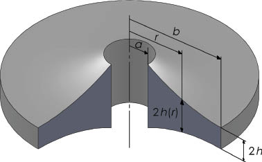
A thin radially FG circular plate with variable cross section.
where n1, n2, and n3 are the elasticity modulus, density, and thickness indexes, respectively. In addition, the material properties of pure aluminum are employed to the outer surface of the disc, i.e., Eo, ρo, and ho are constant. As for the Poisson’s ratio ν, it is assumed as a constant because variation of the Poisson’s ratio has much less practical significance than those in the others. When material properties are taken into consideration as variables, the well-known bending stiffness D for isotropic materials can be rearranged as variable bending stiffness D(r), as follows:
3 Theoretical formulation
The equation of motion of a freely vibrating radially FG thin plate can be written as [20]
where the transverse displacement, w=w(r,θ,t), is a function of three variables and
Substituting Eqs. (6)–(8) into (Eq. 5) yields the governing differential equation of the freely vibrating radially FG thin plates.
4 Solution
In order to solve Eq. (9), the time is separated from the transverse displacement expression as follows:
where ω is the natural frequency of the disc. Substituting Eq. (10) into Eq. (9) results in
Then, the variable θ is also separated from the transverse displacement expression as follows:
where m is the nodal diameter. Finally, substitution of the above mode solution into Eq. (11) leads to
As Eq. (13) is solved, the following general solution can be obtained:
where Jm, Ym, Im, and Km are the Bessel functions of the first and second kind of order m and the modified Bessel functions of the first and second kind of order m, respectively. C1, C2, C3, and C4 are arbitrary constants. kmn and these arbitrary constants are determined from boundary conditions. m is nodal diameter and n is nodal circle, and in this study they are taken as m=0, 1, 2 and n=1, 2. The modes with m=0 are called symmetric modes, whereas those with m≠0 are called asymmetric modes. The roots (kmnr) give the frequencies of free vibration of the disc.
The boundary conditions are applied to the inner and outer surfaces. Two different types of boundary conditions are considered in this study: clamped (C) and simply supported (S). These boundary condition types are described as
The widely used boundary conditions are taken into account at the inner and outer radii of the disc, i.e., C-C, S-S, C-S, and S-C.
When the boundary conditions are applied to Eq. (14), four equations emerge from each boundary condition. The roots of these four equations are obtained from the determinant, which is composed of four equations. As a result, the characteristic equation can be found for each related boundary condition.
In order to calculate the natural frequencies, the characteristic equation is solved by the Newton-Raphson method. The characteristic equation is plotted graphically when the Newton-Raphson method does not converge to find roots. The points where the curve intersects the x axis give the roots, which are the values of the natural frequencies for each mode. The commercial program MAPLE® (Maplesoft, Canada) is used in the calculations and plotting.
In order to support the accuracy of the results obtained from the present method, the disc is also solved by the commercial program ANSYS® (Ansys Inc., USA) using finite element analyses. The disc with variable cross section is modeled by SOLIDWORKS® (SolidWorks Corp., USA) program and imported to ANSYS as IGS files, and then the disc is meshed by a PLANE25 axisymmetric, harmonic, four-node structural solid element. The PLANE25 input data includes the number of harmonic waves. This element is very well suited for computing natural frequencies that have different nodal diameters. Variable material properties of the disc are defined in ANSYS by embedding a do loop code into the session file. In mesh refinement, an element is utilized per millimeter of the radius. This means that 400 axisymmetric elements are utilized for 400 mm in the radial direction. Thus, each mesh element has different material content. The block Lanczos method is used for the eigenvalue extractions to calculate frequencies.
5 Results and discussion
In this study, a radially FG annular circular plate with variable geometry is considered. The material properties (elasticity modulus and density) and geometry (thickness) of the disc vary through the radial direction of the disc, whereas Poisson’s ratio ν is considered as a constant. In addition, the ratio of the inner radius to the outer radius is also taken as a variable. The elasticity modulus, density, thickness, and outer radius of the disc are taken as constant and they are set to Eo=70 GPa, ρo=2700 kg/m3, ho=0.001 m, and b=0.5 m, respectively. Elasticity modulus index (n1), density index (n2), and thickness index (n3) are taken from -0.5 to 0.5 at intervals of 0.25. Moreover, the inner radius (a) is taken from 0.1 m to 0.4 m at intervals of 0.1 m. The power law assumption for material properties and thickness is valid for this interval, and for small values of inner radius this assumption may be meaningless. This assumption is considered as a mathematical model. The FG disc is an isotropic, homogeneous, and uniform disc when the values of n1, n2, and n3 are equal to zero. Moreover, the values of m and n are taken as 0, 1, 2 and 1, 2, respectively, in the calculations.
The natural frequencies of the radially FG disc under C-C boundary conditions are listed in Table 1 for each of the three indexes. Each index is considered separately in order to see only its own effects. It can be seen in Table 1 that natural frequencies decrease with increasing n1 and n3 contrary to n2. Moreover, in this table, the results obtained from the present solution are compared with those from ANSYS®. The percentage error is also given in the table. The table shows that the results of the present method are in good agreement with those of ANSYS®. The results obtained for other boundary conditions, i.e., S-S, C-S, and S-C are given in the figures.
First two frequencies (Hz) of the disc with CC boundary condition.
| Indexes | m=0 | m=1 | m=2 | |||||||||||||||
|---|---|---|---|---|---|---|---|---|---|---|---|---|---|---|---|---|---|---|
| f1 | f2 | f1 | f2 | f1 | f2 | |||||||||||||
| Present | ANSYS | Error (%) | Present | ANSYS | Error (%) | Present | ANSYS | Error (%) | Present | ANSYS | Error (%) | Present | ANSYS | Error (%) | Present | ANSYS | Error (%) | |
| n1 | Model 1 (variable E, constant ρ, constant h) | |||||||||||||||||
| -0.50 | 39.484 | 39.463 | 0.053 | 108.854 | 108.790 | 0.059 | 40.951 | 40.930 | 0.051 | 111.533 | 111.470 | 0.057 | 46.740 | 46.717 | 0.049 | 120.341 | 120.280 | 0.051 |
| -0.25 | 36.591 | 36.580 | 0.030 | 101.175 | 101.050 | 0.124 | 38.059 | 38.048 | 0.029 | 103.649 | 103.640 | 0.009 | 43.762 | 43.750 | 0.027 | 112.112 | 112.080 | 0.029 |
| 0.00 | 33.905 | 33.904 | 0.003 | 93.793 | 93.789 | 0.004 | 35.368 | 35.368 | 0.000 | 96.279 | 96.274 | 0.005 | 40.966 | 40.967 | -0.002 | 104.350 | 104.340 | 0.010 |
| 0.25 | 31.413 | 31.420 | -0.022 | 86.978 | 86.980 | -0.002 | 32.867 | 32.874 | -0.021 | 89.331 | 89.359 | -0.031 | 38.348 | 38.356 | -0.021 | 97.018 | 97.044 | -0.027 |
| 0.50 | 29.099 | 29.114 | -0.052 | 80.612 | 80.599 | 0.016 | 30.540 | 30.554 | -0.046 | 82.865 | 82.869 | -0.005 | 35.886 | 35.902 | -0.045 | 90.129 | 90.160 | -0.034 |
| n2 | Model 2 (variable ρ, constant E, constant h) | |||||||||||||||||
| -0.50 | 29.602 | 29.589 | 0.044 | 81.169 | 81.252 | -0.102 | 30.874 | 30.896 | -0.071 | 84.352 | 83.438 | 1.095 | 35.910 | 35.925 | -0.042 | 90.476 | 90.504 | -0.031 |
| -0.25 | 31.719 | 31.701 | 0.057 | 87.535 | 87.371 | 0.188 | 33.092 | 33.086 | 0.018 | 89.763 | 89.704 | 0.066 | 38.391 | 38.398 | -0.018 | 97.273 | 97.265 | 0.008 |
| 0.00 | 33.905 | 33.904 | 0.003 | 93.793 | 93.789 | 0.004 | 35.368 | 35.368 | 0.000 | 96.279 | 96.274 | 0.005 | 40.966 | 40.967 | -0.002 | 104.350 | 104.340 | 0.010 |
| 0.25 | 36.175 | 36.198 | -0.064 | 98.676 | 100.510 | -1.825 | 37.783 | 37.742 | 0.109 | 102.600 | 103.150 | -0.533 | 43.642 | 43.632 | 0.023 | 111.777 | 111.740 | 0.033 |
| 0.50 | 38.515 | 38.584 | -0.179 | 107.430 | 107.540 | -0.102 | 40.245 | 40.208 | 0.092 | 110.072 | 110.340 | -0.243 | 46.412 | 46.391 | 0.045 | 119.527 | 119.470 | 0.048 |
| n3 | Model 3 (variable h, constant E, constant ρ) | |||||||||||||||||
| -0.50 | 47.641 | 47.683 | -0.088 | 128.337 | 128.440 | -0.080 | 48.950 | 48.891 | 0.121 | 131.048 | 131.150 | -0.078 | 54.427 | 54.469 | -0.077 | 140.136 | 140.240 | -0.074 |
| -0.25 | 40.042 | 40.080 | -0.095 | 109.640 | 109.710 | -0.064 | 41.435 | 41.472 | -0.089 | 112.266 | 112.330 | -0.057 | 47.025 | 47.056 | -0.066 | 120.905 | 120.970 | -0.054 |
| 0.00 | 33.905 | 33.904 | 0.003 | 93.793 | 93.789 | 0.004 | 35.368 | 35.368 | 0.000 | 96.279 | 96.274 | 0.005 | 40.966 | 40.967 | -0.002 | 104.350 | 104.340 | 0.010 |
| 0.25 | 28.945 | 28.950 | -0.017 | 80.389 | 80.362 | 0.034 | 30.453 | 30.458 | -0.016 | 82.745 | 82.672 | 0.088 | 35.957 | 35.961 | -0.011 | 90.063 | 90.070 | -0.008 |
| 0.50 | 24.920 | 24.922 | -0.008 | 68.787 | 68.935 | -0.215 | 26.440 | 26.442 | -0.008 | 71.620 | 71.040 | 0.816 | 31.746 | 31.747 | -0.003 | 77.620 | 77.701 | -0.104 |
5.1 Effect of elasticity modulus
Figure 2 illustrates the variations of the natural frequencies of radially FG disc with change in n1 for S-S, C-S, and S-C boundary conditions. In order to see only the effect of the elasticity modulus, n2 and n3 are taken as zero. It can be seen from Figure 2A–C that the natural frequencies decrease with increasing n1. In other words, the natural frequencies decrease with decreasing elasticity modulus at the inner surface of the disc. As a result, in order to increase the natural frequencies, the material at the inner surface of the disc should have higher stiffness.

Effects of n1 variations on the natural frequency of the disc for (A) S-S, (B) C-S, and (C) S-C boundary conditions. * (m=0; n=1), ○ (m=0; n=2), □ (m=1; n=1), △ (m=1; n=2), ⋄ (m=2; n=1), ▽ (m=2; n=2).
As can be seen from Figure 2, the natural frequencies that vary with increasing nodal circle n are higher than those with increasing nodal diameter m. It can also be deduced from Figure 2 and Table 1 that the highest values of the natural frequencies are obtained for the C-C boundary condition.
5.2 Effect of density
Figure 3 shows the variations of the natural frequencies of radially FG disc with change in n2 for S-S, C-S, and S-C boundary conditions. However, n1 and n3 are taken as zero. Contrary to the results obtained for n1, the natural frequencies increase with increasing n2. In other words, the natural frequencies increase with decreasing density at the inner surface of the disc. As a result, in order to increase the natural frequencies, the material at the inner surface of the disc should have lower density.

Effects of n2 variations on the natural frequency of the disc for (A) S-S, (B) C-S, and (C) S-C boundary conditions. * (m=0; n=1), ○ (m=0; n=2), □ (m=1; n=1), △ (m=1; n=2), ⋄ (m=2; n=1), ▽ (m=2; n=2).
The variation of the natural frequencies with changing nodal circle n and nodal diameter m is almost the same in Figures 2 and 3.
5.3 Effect of thickness
It can be seen from Figure 4 that the natural frequencies gradually decrease with increasing n3 when n1=n2=0. As a result, narrowing discs can provide more advantages because they have higher natural frequencies than expanding discs. However, the weight of the disc increases. It is also seen from Figures 2–4 that the slopes of the curves in Figure 4 are steeper than those in Figures 2 and 3. This means that the influence of n3 on the natural frequency of the disc is more effective than those of n1 and n2.

Effects of n3 variations on the natural frequency of the disc for (A) S-S, (B) C-S, and (C) S-C boundary conditions. * (m=0; n=1), ○ (m=0; n=2), □ (m=1; n=1), △ (m=1; n=2), ⋄ (m=2; n=1), ▽ (m=2; n=2).
5.4 Effect of the ratio of the inner radius to the outer radius
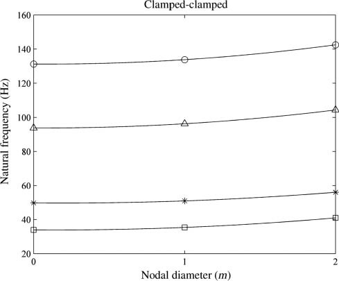
The variation of the natural frequencies of radially FG disc with change in a (inner radius) for the C-C boundary condition is depicted in Figure 5. It can be seen from this figure that the variation of the nodal diameter m has almost no effect on the natural frequency, whereas the variation of the nodal circle n has more effect when the inner surface approaches the outer surface. The effect on the natural frequency of the second nodal circle, especially in the range 0.6–0.8, is very high.

Effects of a/b variations on the natural frequency of the isotropic disc for C-C boundary conditions. * (m=0; n=1), ○ (m=0; n=2), □ (m=1; n=1), △ (m=1; n=2), ⋄ (m=2; n=1), ▽ (m=2; n=2).
5.5 Effect of the combination of all indexes
The above-mentioned effects of indexes are investigated separately. Each effect is valid for only the corresponding index. To see the effect of all indexes together on the natural frequency, a FG disc for which material and geometric indexes are n1=-0.5, n2=-0.5, and n3=-0.5 is compared with an isotropic, homogeneous disc. Figure 6 represents the variations of the natural frequencies of radially FG disc with change in m (nodal diameter) for C-C boundary conditions. It can be seen from the figure that the natural frequencies of radially FG disc are higher than those of the isotropic, homogeneous disc, and the natural frequencies increase with increasing m. The ratio of the increase is almost the same for both discs.
Comparison of variations in the natural frequencies of FGM and isotropic discs with nodal diameter (m) for C-C boundary conditions. * (FGM; n=1), ○ (FGM; n=2), □ (isotropic; n=1), △ (isotropic; n=2).
5.6 Mode shapes
Mode shapes of the disc with variable thickness (n3=-0.5) for the ratio of the inner radius to the outer radius (a/b=0.2 and 0.8) are illustrated in Figures 7 and 8, respectively. It can be seen from the figures that the mode shapes with m=0 are axisymmetric, and the others are asymmetric. The nodal diameters and nodal circles of the disc can be clearly seen in the figures. It can also be seen from Figures 7 and 8 that the characteristics of the mode shapes of the discs with different inner radii are very similar to each other.

Mode shape of the C-C disc for a/b=0.2 and n3=-0.5. (A) m=0; n=1, (B) m=0; n=2, (C) m=1; n=1, (D) m=1; n=2, (E) m=2; n=1, (F) m=2; n=2.
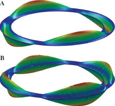
Mode shape of the C-C disc for a/b=0.8 and n3=-0.5. (A) m=2; n=1, (B) m=2; n=2.
6 Conclusions
In this study, free vibration of a disc that has constant material and geometric properties at the outer surface but variable at the interior region is examined. The results obtained from the present study are supported with ANSYS® commercial software. In the analysis, the effects of elasticity modulus, density, thickness, and the ratio of the inner radius to the outer radius are investigated. Moreover, the mode shapes of the disc are also discussed. In the light of the above investigation, the following conclusions can be drawn.
In order to increase the natural frequency of a radially FG disc,
the elasticity modulus of the disc should be increased at the inner surface,
the density of the disc should be increased at the outer surface, and
the thickness of the disc should be increased at the inner surface.
The natural frequencies vary very little with increasing nodal diameter m, whereas they vary more with increasing nodal circle n.
The effect of the a/b ratio on the natural frequency is very efficient. Especially after a/b=0.6, the natural frequency increases rapidly with increasing ratio of a/b. However, the results show that the a/b ratio has no effect on the mode shape.
Finally, the natural frequency of a FG disc can be altered by arranging the distribution of material constituent as compared to the isotropic, homogeneous disc.
Acknowledgments
The authors would like to thank the Pamukkale University Scientific Research Council for supporting this study under Project Contract No. 2011BSP013 and 2011BSP014.
References
[1] Zenkour AM, Sobhy M. Compos. Struct. 2010, 93, 93–102.Search in Google Scholar
[2] Çallioğlu H, Sayer M, Demir E. Indian J. Eng. Mater. Sci. 2011, 18, 111–118.Search in Google Scholar
[3] Jomehzadeh E, Saidi AR, Atashipour SR. Mater. Des. 2009, 30, 3679–3685.Search in Google Scholar
[4] Shahba A, Rajasekaran S. Appl. Math. Model 2012, 36, 3088–3105.10.1016/j.apm.2011.09.073Search in Google Scholar
[5] Hosseini-Hashemi Sh, Azimzadeh-Monfared M, Rokni Damavandi Taher H. Int. J. Eng. Sci. 2010, 48, 1971–1984.Search in Google Scholar
[6] Nie GJ, Zhong Z. Comput. Methods Appl. Mech. Eng. 2007, 196, 4901–4910.Search in Google Scholar
[7] Allahverdizadeh A, Naei MH, Nikkhah Bahrami M. J. Sound Vib. 2008, 310, 966–984.Search in Google Scholar
[8] Wang Y, Xu RQ, Ding HJ. Appl. Math. Mech. Eng. Ed. 2009, 30, 1077–1082.Search in Google Scholar
[9] Ebrahimi F, Rastgo A. Thin Walled Struct. 2008, 46, 1402–1408.Search in Google Scholar
[10] Hosseini-Hashemi Sh, Es’haghi M, Karimi M. Int. J. Mech. Sci. 2010, 52, 410–428.Search in Google Scholar
[11] Prakash T, Ganapathi M. Composites, Part B 2006, 37, 642–649.10.1016/j.compositesb.2006.03.005Search in Google Scholar
[12] Nie GJ, Zhong Z. Compos. Struct. 2008, 84, 167–176.Search in Google Scholar
[13] Shi P, Dong CY. J. Sound Vib. 2012, 331, 3649–3662.Search in Google Scholar
[14] Malekzadeh P, Haghighi MRG, Atashi MM. Meccanica 2011, 46, 893–913.10.1007/s11012-010-9345-5Search in Google Scholar
[15] Mirtalaie SH, Hajabasi MA, Proc. Inst. Mech. Eng., Part C 2011, 225, 568–583.10.1243/09544062JMES2232Search in Google Scholar
[16] Mehrabadi SJ, Kargarnovin MH, Najafizadeh MM. J. Mech. Sci. Technol. 2009, 23, 2008–2021.Search in Google Scholar
[17] Nikkhah-Bahrami M, Shamekhi A. In ASME 2005 International Design Engineering Technical Conferences and Computers and Information in Engineering Conference, Proceedings 2005, 1, 1963–1969.Search in Google Scholar
[18] Laura PAA, Gutierrez RH, Carnicer R, Sanzi HC. J. Sound Vib. 1991, 144, 149–161.Search in Google Scholar
[19] Tajeddini V, Ohadi A, Sadighi M. Int. J. Mech. Sci. 2011, 53, 300–308.Search in Google Scholar
[20] Birman V. Plate Structures, Springer: London, 2011, doi: 10.1007/978-94-007-1715-2.10.1007/978-94-007-1715-2Search in Google Scholar
©2014 by Walter de Gruyter Berlin Boston
This article is distributed under the terms of the Creative Commons Attribution Non-Commercial License, which permits unrestricted non-commercial use, distribution, and reproduction in any medium, provided the original work is properly cited.
Articles in the same Issue
- Frontmatter
- Original articles
- Microstructures and physical properties of laser amorphous reinforced composite coatings
- The thermal resistance, flame retardance, and smoke control mechanism of nano MH/GF/NBR composite material
- The effect of sodium hydroxide treatment and fiber length on the tensile property of coir fiber-reinforced epoxy composites
- Evaluation of morphological characteristics and mechanical performance of Rockforce mineral fiber- and glass fiber-reinforced polyamide-6 composites
- Synthesis of superabsorbent resin with the properties of temperature tolerant, salt tolerant, and water absorbency deferred
- A study on tribological characterization of Al-Cu-Mg-B composites subjected to mechanical wear
- Microstructure and wear behavior of TiAl3 matrix self-lubricating composites by addition of fluoride solid lubricants
- Mechanical properties of Ni-nano-Al2O3 composite coatings on AISI 304 stainless steel by pulsed electrodeposition
- Improvement of Khorasan mortar with fly ash for restoration of historical buildings
- Combined effect of waste colemanite and silica fume on properties of cement mortar
- Effect of heat treatment temperature on ground pumice activation in geopolymer composites
- Stress intensity factor analysis of epoxy/SWCNTs based on global-local multiscale method
- Numerical elastoplastic analysis of the shear stress distribution in the adhesive layer for single-lap joints
- Analysis of three-layer composite plates with a new higher-order layerwise formulation
- Ceramic-polytetrafluoroethylene composite material-based miniaturized split-ring patch antenna
- Prediction of the influence of processing parameters on synthesis of Al2024-B4C composite powders in a planetary mill using an artificial neural network
- Different method to make laminates by shear thickening fluid
- Thermal control design for an automated fiber placement machine
- Estimate of cutting forces and surface roughness in end milling of glass fiber reinforced plastic composites using fuzzy logic system
- Electrical discharge machining of Al-TiB2 with a low-frequency vibrating tool
- Vibration behavior of a radially functionally graded annular disc with variable geometry
- Buckling behaviors of the impacted composite plates