Giant enhancement of second harmonic generation from monolayer 2D materials placed on photonic moiré superlattice
-
Tingyin Ning
 ,
Lina Zhao
,
Lina Zhao
 ,
Yanyan Huo
,
Yanyan Huo

Abstract
We numerically investigate second harmonic generation (SHG) from a monolayer of 2D-material placed on photonic moiré superlattice fabricated by dielectric materials. The greatly enhanced local field at the resonance modes of moiré superlattice can dramatically boost the SHG response in 2D materials. Considering a typical 2D-material MoS2 monolayer placed on a photonic moiré superlattice of a twist angle 9.43°, the maximum SHG conversion efficiency reaches up to 10−1 at a relatively low intensity of fundamental light 1 kW/cm2, which is around 14 orders of magnitude larger than that from the monolayer placed on a flat dielectric slab without moiré superlattices. The SHG conversion efficiency from the monolayer can be further enhanced with the decrease of the twist angles of moiré superlattice due to the even more confinement of local field. The flat bands in the moiré superlattices formed by the small twist angles can particularly ensure the efficiency even under wide-angle illuminations. The results indicate that photonic moiré superlattice which can tightly confine light is a promising platform for efficient nonlinear optics.
1 Introduction
Second harmonic generation (SHG), as one of the most fundamental nonlinear optical phenomena, has important applications in the fields such as short-wavelength light sources, imaging, and sensing [1]. SHG in two-dimensional (2D) monolayer materials has received much interest and has been extensively investigated in recent years, since 2D materials, such as graphene and transition metal dichalcogenides (TMDs), possess large and tunable nonlinear susceptibilities in a broad band [2–7]. Such 2D materials can also be easily integrated into photonic platforms including fibers, waveguides, micro-rings, and so on, due to their excellent flexibility and mechanical properties [8–10]. However, the monolayer thickness unavoidably limits the efficiency of their nonlinear response. The boost of SHG in 2D materials is essentially required for applications. Until now, various methods have been utilized to enhance the nonlinear response in 2D monolayer materials, such as the excitation of surface plasmon [11–13], exciton resonance [14], 2D materials integrated with metallic substrate or nanostructures [15–17], photonic crystals [18–20], waveguide [21–23], or other cavities [24–26], etc.
The moiré superlattices, formed by two periodical patterns with a twist angle or a mismatched lattice constant, has drawn much attention due to the unexpected novel physical properties [27–31]. Besides the widely studied novel electronic states in condensed matter physics, the photonic moiré superlattices were found to have the ability to extremely confine the light field [32, 33]. Particularly, moiré superlattices possess flat bands in the whole moiré Brillouin zone. Flat bands have non-dispersive features which mean that the group velocity of light is zero to enhance the light–matter interaction. Further, the non-dispersive feature indicates that the resonant frequencies of moiré superlattices are independent on the angle of incidence. The light from different propagation directions, for example, when the light is focused on the nanostructure using objective lens of high numerical aperture, can work together to improve the efficiency in various applications. The other cavities, such as traditional photonic crystals of simple lattice, metasurfaces of (quasi-)BICs, can also have ultrahigh Q-factor and confine the field tightly at the resonance modes. However, there are no or just local flat bands, and the resonant frequencies highly depend on the propagation directions, which limits their performance under wide-angle illuminations. Thus, the photonic moiré superlattices have important applications in light–matter interactions, including low-threshold lasing [34], ultra-low level all-optical switching [35], wide-angle linear and nonlinear optical devices [36, 37], and tunable harmonic generations in the twisted 2D materials [38–40]. Just recently, the photonic moiré superlattice was demonstrated to boost SHG in monolayer van der Waals crystals [41]. The SHG efficiency in WS2 monolayer placed between the moiré superlattice was enhanced up to be 2.67 × 10⁻⁸ at the intensity of fundamental light 0.1 GW/cm2, which was 600 times larger than that from a free-standing WS2 monolayer. However, the photonic moiré superlattice used in the article, which was formed by a mismatched bilayer grating, with a 2D material monolayer between the stacks was not easy to be fabricated experimentally. Furthermore, the 2D material monolayers of nonzero absorption coefficient inside the cavity dramatically attenuate the quality factor of resonance systems.
In this article, we report the efficient SHG in monolayer 2D materials covered on a photonic moiré superlattice. The dramatically enhanced local field on the surface of photonic moiré superlattices leads to the efficient SHG at relatively low fundamental intensities. The flat bands in the photonic moiré superlattices formed by the small twist angles can particularly ensure the efficiency even under wide-angle illuminations. The results indicate the promising applications of photonic moiré superlattices in nonlinear optical harmonic generations.
2 Moiré superlattice and numerical method
We consider a moiré superlattice formed by twisting two layers of triangular lattices in the same dielectric membrane, as investigated in Ref. [42]. Such moiré superlattices have been fabricated using the electron-beam lithography technique combining with the etching processing [34], indicating a feasible structure for experiments. Different twist angles θ will lead to the superlattices of different periods by a = a 0/(2sin(θ/2)), where a 0 and a are the lattice constants of basic triangular lattice and moiré superlattice, respectively. For example, when a twist angle is 9.43°, the lattice constant of the superlattice is around 3.04 μm. The schematic structure of a moiré superlattice of a twist angle 9.43° is shown in Figure 1(a). The lattice constant of the basic triangular lattice is 500 nm, and the radius of nanohole is 120 nm. Here, MoS2 monolayer, as typical TMDs, is considered. A MoS2 monolayer is placed on the surface of moiré superlattices, as shown in Figure 1(b).
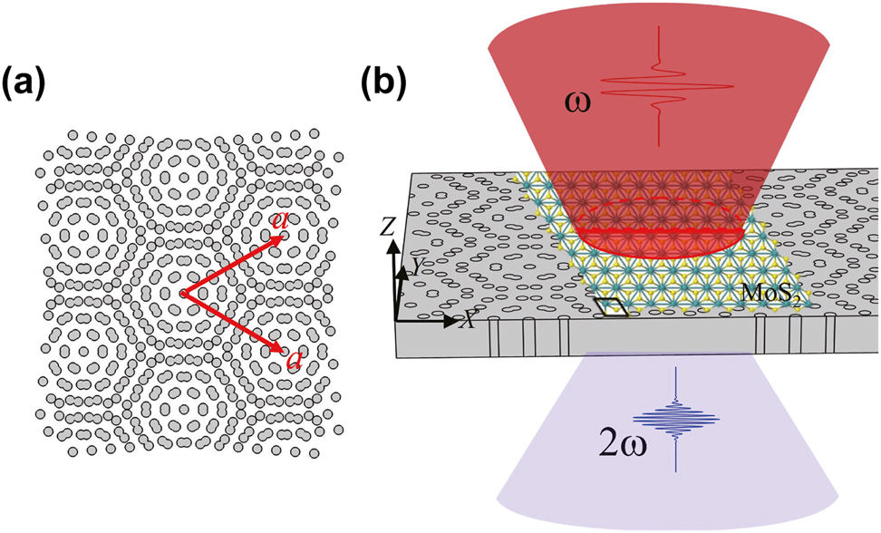
Schematic structure of (a) a moiré superlattice (a is the lattice constant, twist angle θ = 9.43°), and (b) a MoS2 monolayer placed on the moiré superlattice.
The wave equation for the fundamental and SHG fields in the frequency domain (time-harmonic factor exp(−iωt)) can be expressed as [1, 42],
where Ω = 2ω is the angular frequency of SHG, E(ω) and E(Ω) are fundamental and SHG electric fields, respectively. k 0 = ω/c and k 2 = Ω/c are the wave vectors of the fundamental and SH lights, respectively, where c is the speed of light in a vacuum. ɛ 0 is the vacuum permeability. ɛ 2 is the relative permittivity of materials at SH frequency.
The linear polarization for MoS2 and the dielectric moiré superlattice is written as P
(1)(ω) = ɛ
0(ɛ − 1)E(ω), where ɛ
0 and ɛ are the vacuum permittivity and the relative permittivity of materials, respectively. The ɛ of the dielectric materials is taken as 11.56, which corresponds to the materials, such as amorphous Al doped GaAs (Al
x
Ga1−x
As) or silicon, and the ɛ of MoS2 is referred the experimental data [43]. Due to the symmetry structure of amorphous Al doped GaAs or Si, there is no bulk SHG response from the moiré superlattices. SHG from MoS2 is solely considered. For MoS2, the bulk crystal belongs to the D
6h
space group and has the inversion symmetry, while the inversion symmetry is broken in the monolayer and it changes to be D
3h
space group [44]. The non-vanished second-order nonlinear susceptibility of the MoS2 monolayer is
and the components of P (2)(Ω) in MoS2 is expressed as,
The polarization in the MoS2 monolayer can also be described by the surface current using J(ω) = −iω
P(ω) or J(Ω) = −iΩP(Ω) at the fundamental and SHG fields, respectively. In nonlinear surface current treatment, the bulk second-order nonlinear susceptibility χ
(2) should be replaced by the surface second-order nonlinear susceptibility
The coupled equations can be numerically solved by finite element methods assisted by the commercial software Comsol Multiphysics in the frequency domain. The settings can be referred in our previous articles, such as [42]. The settings can be referred in our previous articles, such as [42]. Basically, the simulation domain of a unit cell of moiré superlattice is shown in Figure 2. For the linear optical properties, the conventional one step method is used. The top boundary is set as port 1 used for the incidence of light, and the component of electric field E x or E y corresponds to the x- or y-polarized illumination, respectively. The bottom boundary is noted as port 2. The periodic boundary conditions (PBCs) are employed on the surrounding boundaries, and the Floquet periodicity vector k F is set as 0 at normal incidence. The transmission is calculated using |S 21|2, where S 21 is the S-parameter for the transmitted wave. The distribution of fields can be required at the desired wavelength. For the SHG simulation, two steps must be conducted. The first step is similar as the aforementioned settings to calculate the fundamental field which is used to express the second-order polarizations (Eqs. (5) and (6)). The second step is to calculate the generated second harmonic signal. The scatter field calculation with the zero background field is used. The PBCs are still employed on the surrounding boundaries, but the Floquet periodicity vector should be twice of fundamental k F generally. The power of generated SHG signal, PSHG, can be obtained by the integration of Poynting flow at 2ω on the port one for reflected SHG and the port two for transmitted SHG. The conversion efficiency of SHG is defined as η = P SHG/P in, where P in is the incident fundamental power. It is noting that for the monolayer MoS2, the surface current given by the fundamental and second-order polarizations is used to replace the real thickness layer.
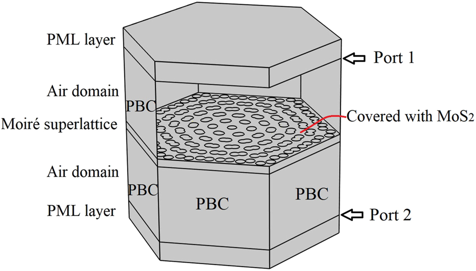
The simulation domain and related settings in the Comsol Multiphysics. The unit cell of moiré superlattice covered with a MoS2 monolayer is placed in the vacuum environment. The perfect matched layers (PML) are vacuum, and the periodic boundary conditions (PBCs) are employed on the surrounding boundaries.
The eigenfrequency and band structures are simulated by the eigenfrequency solver in Comsol Multiphysics. The settings in the domain of a unit cell of moiré superlattice are similar as those for linear optical properties. The Floquet vector k F changes along the edges of irreducible Brillouin zone.
3 Results and discussion
The eigenfrequency of the bare moiré superlattices is first studied to find the resonance modes. The band structures of moiré superlattices formed by different twist angles are shown in Figures 3 and 4. The dipole modes P x and P y , which contribute to the flat bands are marked in dashed red box. Especially, the perfect flat band can be formed in the whole moiré Brillouin zone under the small angle 2.65° (Figure 4(b) and (c)) and even smaller angles. At such moiré superlattices, the non-dispersion flat bands are exactly immune to the light propagation directions. The nearly degenerated dipole modes P x and P y in moiré superlattices of different commensurate twist angles are specially shown in Figure 5. The field distributions of the two modes are shown in the inset of Figure 5. It is clear that the eigenfrequency can be significantly modulated by the twist angles, which can cover a broadband to enhance the nonlinear response of the 2D monolayer materials on the structures. Considering the computational consumption, we next mainly study the optical responses from the moiré superlattice of the twist angle 9.43° to demonstrate how the confined local field on the moiré superlattice to enhance the 2D monolayer MoS2 covered on it.
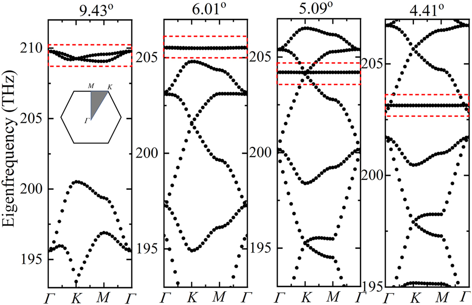
Band structures of moiré superlattices formed by different twist angles. The flat bands formed by the dipole modes P x and P y are marked in dashed red box. The inset of the first figure shows the Brillouin zone.

Band structure of moiré superlattices formed by the twist angle 2.65° and the flat band diagrams. (a) The band structure in a wide frequency range. (b) and (c) Are the enlarged band diagrams of flat band from the px mode (marked in dashed red box) in moiré superlattices of the twist angle 4.41° and 2.65°, respectively.
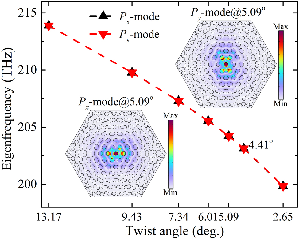
Eigenfrequency analysis of dipole modes P x and P y in moiré superlattices formed by different commensurate twist angles. The typical field distribution at P x and P y are shown in the inset of figure.
The linear transmittance in the nanostructure can be obtained by solving Eq. (1) when the SHG process is not considered, as shown in Figure 6(a). The light of the polarization along x- and y-axis at normal incidence is considered, respectively. The two dipole modes, P x and P y , are observed, as those in the pure dielectric moiré superlattice [34, 35]. The resonance wavelength at P x and P y modes is around 1427.3585 nm and 1427.3685 nm, respectively. Comparing with the moiré superlattice without the MoS2 monolayer, the transmission spectra only have a blueshift due to the change of environment dielectric constant from air to the MoS2 monolayer. The lineshapes are almost kept since the MoS2 monolayer at such wavelength region has no absorption. The Q factors at P x and P y modes are calculated by Q = λ r/δλ r for the Fano lineshape, where λ r and δλ r are the resonance wavelength and the difference of wavelength at peak and dip, respectively. The Q factors under the x(y)-polarization incidence are around 1 × 10⁷ (2.4 × 10⁵) and 2.4 × 10⁵ (6.5 × 10⁷) at the P x and P y modes, respectively. It is worth noting that the Q factor can also be obtained by the eigen-frequency solver. The values of the in-plane Q factor and vertical Q factor are infinity and 1.42 × 10⁴, respectively. So the incident light of the linear x- or y-polarization can excite the in-plane resonant modes but with out-of-plane decay or leaky modes to free space. The difference of the maximum Q factors at the incident light of x- and y-polarization may be ascribed to the different confinement size in a unit cell along x- and y-axis.
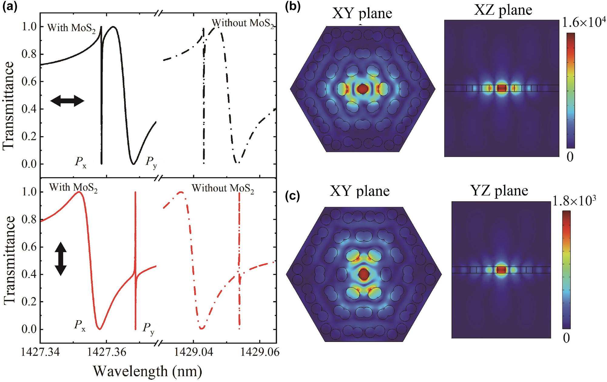
Linear transmittance and field distributions. (a) The linear transmittance of the nanostructure under the x- and y-polarized incidence, respectively. The bold arrows represent the directions of the polarization, along x- or y-axis. (b) and (c) Show the field distribution at Px and Py modes under the x-polarized incidence, respectively. (b) XY-plane and XZ-plane, and (c) XY-plane and YZ-plane. The values of colorbar represent the local field enhancement.
When the intensity of fundamental light is 1 kW/cm2, the spectra of SHG conversion efficiency under the fundamental light of different polarizations are shown in Figure 7(a). Two peaks appear around the resonance modes at the fundamental light of x- or y-polarization, respectively, due to the enhancement of local fundamental electric fields. The positions of the peaks of SHG conversion efficiency are not exact overlapped with the corresponding P y and P x resonance modes, since the SHG conversion efficiency is conjoint determined by the local fundamental field and the SHG field, and the P (1)(ω) from the mixing of fundamental and SHG waves in MoS2 is not negligible to shift the resonance modes at such pump intensity. It is worth noting that maximum SHG conversion efficiencies arrive up to 10−6 and 10−2 around the P y and P x modes at the x-polarized fundamental light, respectively. The value even reaches up to about 10−1 around the P y mode at the y-polarized fundamental light. For the MoS2 monolayer on the flat dielectric slab without moiré nanostructures, the conversion efficiency is only around 7.3 × 10⁻¹⁷ at the pump intensity 1 kW/cm2. The maximum enhancement of SHG is around 14 to 15 orders of magnitude at the P x mode (x-polarized fundamental light) and P y mode (y-polarized fundamental light). Such efficiency is also much larger than that from the 2D materials monolayer integrated with various resonance cavities even at the higher intensity of fundament light [19, 20, 24, 25]. Particularly, the non-dispersive flat bands in the whole moiré Brillouin zone of moiré superlattices can enable the high efficiency to be kept under the wide-angle illumination, which is superior to the other traditional resonance cavities of dispersive band structures or just local flat bands. The SHG field distributions at the two maximum peaks at the fundamental light of x- and y-polarization are shown in Figure 7(b) and (c), respectively. When the fundamental wavelength is fixed at the resonance mode, i.e. P x or P y mode, the dependence of SHG conversion efficiency on the intensity of fundamental light is shown in Figure 8. The slopes of the value 1 indicate the second-order nonlinear process. The derivation of 1 as the increase of the pump intensity of fundamental light is ascribed to the P (1)(ω) due to the mixing of fundamental and SHG waves in MoS2 which shifts the resonance mode. Such large conversion efficiency in the 2D monolayers indicates the moiré superlattice is a promising platform for nonlinear photonics.

SHG response and field distributions. (a) Dependence of SHG conversion efficiency on the fundamental wavelength. The intensity of fundamental light is 1 kW/cm2. (b) and (c) Show the SHG field distribution in the XY-plane around the Px (fundamental light of the x-polarization) and Py (fundamental light of the y-polarization) resonance mode, respectively. The plane is chosen at the center of moiré superlattice. The units of colorbar are V/m.
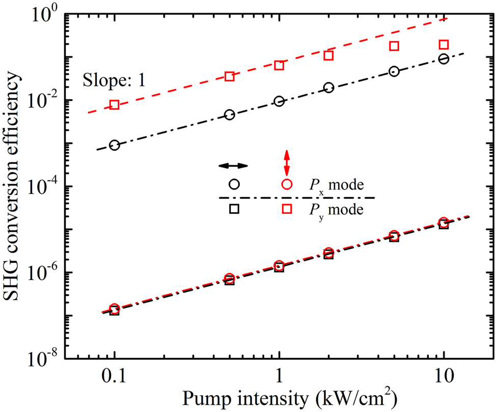
SHG conversion efficiency versus the input intensity of fundamental light at the P x and P y resonance mode when the polarization of fundamental light is along the x- or y-axis, respectively.
When the twist angle is reduced to be 6.01°, the resonance modes of moiré superlattice shift to 1456.709 nm (P x mode) and 1456.715 nm (P y mode) and the superlattice exhibits more confined field distribution. The maximum enhancement factor of local field is around 2.6 × 10⁴ (at the P x mode) and 2.9 × 10⁴ (at the P y mode) under the x- and y-polarization, respectively. The values are larger than those in moiré superlattices formed by the twist angle 9.43°. Under the low intensity of fundamental light 0.1 kW/cm2, the maximum SHG conversion efficiencies from a monolayer MoS2 are up to 6.5 × 10⁻³ (at the P x mode) and 1.2 × 10⁻² (at the P y mode) at the illumination of x- and y-polarized fundamental light, respectively. It is noting that, besides the decrease of the twist angle for moiré superlattice to enhance the SHG, the further enhancement of SHG response depends on the optimization of nanostructures. The parameters of simple triangular lattices (the thickness of the slab, the radius of the holes, and the lattice constant) significantly affect the resonance modes even under the same twist angles. Experimentally, the limitation of the enhancement highly depends on the quality of materials and fabrications. Especially, the defects introduced during the nanofabrication and the surface roughness may dramatically decrease the Q factor due to the scattering and leaky processes to harm the SHG response.
Finally, we point out that the experimental verification of the numerical model is feasible. Nanostructured moiré superlattices formed by the triangular lattice of proper size of holes (radius 120 nm) and lattice constant (500 nm) can be fabricated by the state-of-the-art E-beam lithography and the etching processes, as reported in Ref. [34]. The wafer-scale monolayer MoS2 can be grown by chemical vapor deposition (CVD) method [46, 47] and can be transferred onto the desired substrates [46–49]. The linear optical transmission of the samples can be conducted using the supercontinuum generation laser as a light source and detectors (e.g. photodiode, photomultiplier tube, CCD). An optical parametric oscillator (OPO) femto-laser can be used for the measurement of SHG in the samples. The wavelength is tuned to the resonance states of the samples. Considering the laser of pulse repetition 80 MHz and pulse duration 200 fs, and the laser spot of 200 μm2 fully covering one unit of moire superlattice (9.43°, 8 μm2, 5.09°, 27.5 μm2, and 2.65°, 101.2 μm2), the average power of laser 1 μW can achieve the peak intensity 31.25 kW/cm2 for efficient SHG. The signals can be detected by the sensitive detectors, such as, photomultiplier tube, CCD, avalanche photodiode.
4 Conclusions
We investigate SHG response in monolayer 2D materials placed on the photonic moiré superlattice. The SHG conversion efficiency in 2D materials can be significantly enhanced via the greatly enhanced local field at the resonance modes of the moiré superlattice. For a typical TMD monolayer, such as MoS2, the maximum SHG conversion efficiency reaches up to 10−1 at an intensity of fundamental light 10 kW/cm2, which is about 14 orders of magnitude larger than that from the monolayer placed on a flat dielectric slab. Such nonlinear response from the monolayer can be further enhanced under the smaller twist angles of moiré superlattice. The flat bands in the whole moiré Brillouin zone enable the high efficiency from the nanostructure under the wide-angle illumination. Further, the intrinsic third-order optical nonlinearity of dielectrics is not considered for the simplification, which may shift the resonance frequency due to the change of refractive index and reduce the local field. However, the results still open a new possibility for enhancement of SHG in 2D-material monolayer based on photonic moiré superlattices.
Funding source: National Natural Science Foundation of China
Award Identifier / Grant number: 12274271,12174228
-
Research funding: National Natural Science Foundation of China (12274271, 12174228).
-
Author contributions: All authors have accepted responsibility for the entire content of this manuscript and approved its submission.
-
Conflict of interest: Authors state no conflicts of interest.
-
Data availability: The datasets generated and/or analysed during the current study are available from the corresponding author upon reasonable request.
References
[1] R. W. Boyd, Nonlinear Optics, 3rd ed., San Diego, Academic Press, 2008.Suche in Google Scholar
[2] N. Kumar, S. Najmaei, Q. Cui, et al.., “Second harmonic microscopy of monolayer MoS2,” Phys. Rev. B, vol. 87, p. 161403, 2013. https://doi.org/10.1103/PhysRevB.87.161403.Suche in Google Scholar
[3] L. M. Malard, T. V. Alencar, A. P. M. Barboza, K. F. Mak, and A. M. de Paula, “Observation of intense second harmonic generation from MoS2 atomic crystals,” Phys. Rev. B, vol. 87, p. 201401, 2013. https://doi.org/10.1103/PhysRevB.87.201401.Suche in Google Scholar
[4] K. L. Seyler, J. R. Schaibley, P. Gong, et al.., “Electrical control of second-harmonic generation in a WSe2 monolayer transistor,” Nat. Nanotechnol., vol. 10, pp. 407–411, 2015. https://doi.org/10.1038/nnano.2015.73.Suche in Google Scholar PubMed
[5] T. Jiang, D. Huang, J. Cheng, et al.., “Gate-tunable third-order nonlinear optical response of massless Dirac fermions in graphene,” Nat. Photonics, vol. 12, pp. 430–436, 2018. https://doi.org/10.1038/s41566-018-0175-7.Suche in Google Scholar
[6] L. Mennei, M. Paur, and T. Mueller, “Second harmonic generation in strained transition metal dichalcogenide monolayers: MoS2, MoSe2, WS2, and WSe2,” APL Photonics, vol. 4, p. 034404, 2019. https://doi.org/10.1063/1.5051965.Suche in Google Scholar
[7] S. Klimmer, O. Ghaebi, Z. Gan, et al.., “All-optical polarization and amplitude modulation of second-harmonic generation in atomically thin semiconductors,” Nat. Photonics, vol. 15, pp. 837–842, 2021. https://doi.org/10.1038/s41566-021-00859-y.Suche in Google Scholar
[8] A. C. Ferrari, F. Bonaccorso, V. Falko, et al.., “Science and technology roadmap for graphene, related two-dimensional crystals, and hybrid systems,” Nanoscale, vol. 7, pp. 4598–4810, 2015. https://doi.org/10.1039/C4NR01600A.Suche in Google Scholar
[9] Z. Liu, J. Liu, P. Yin, et al.., “2D Xenes: optical and optoelectronic properties and applications in photonic devices,” Adv. Funct. Mater., vol. 10, p. 2206507, 2022. https://doi.org/10.1002/adfm.202206507.Suche in Google Scholar
[10] S. Yu, X. Wu, Y. Wang, X. Guo, and L. Tong, “2D materials for optical modulation: challenges and opportunities,” Adv. Mater., vol. 29, p. 1606128, 2017. https://doi.org/10.1002/adma.201606128.Suche in Google Scholar PubMed
[11] J. D. Cox, I. Silveiro, and F. G. de Abajo, “Quantum effects in the nonlinear response of graphene plasmons,” ACS Nano, vol. 10, no. 2, pp. 1995–2003, 2016. https://doi.org/10.1021/acsnano.5b06110.Suche in Google Scholar PubMed
[12] Y. Zhao, Y. Huo, B. Man, and T. Ning, “Grating-assisted surface plasmon resonance for enhancement of optical harmonic generation in graphene,” Plasmonics, vol. 14, pp. 1911–1918, 2019. https://doi.org/10.1007/s11468-019-00986-x.Suche in Google Scholar
[13] F. Karimi, S. Soleimanikahnoj, and I. Knezevic, “Tunable plasmon-enhanced second-order optical nonlinearity in transition metal dichalcogenide nanotriangles,” Phys. Rev. B, vol. 103, p. L161401, 2021. https://doi.org/10.1103/PhysRevB.103.L161401.Suche in Google Scholar
[14] G. Wang, X. Marie, I. Gerber, et al.., “Giant enhancement of the optical second-harmonic emission of WSe2 monolayers by laser excitation at exciton resonances,” Phys. Rev. Lett., vol. 114, p. 097403, 2015. https://doi.org/10.1103/PhysRevLett.114.097403.Suche in Google Scholar PubMed
[15] J. Zeng, M. Yuan, W. Yuan, et al.., “Enhanced second harmonic generation of MoS2 layers on a thin gold film,” Nanoscale, vol. 7, pp. 13547–13553, 2015. https://doi.org/10.1039/C5NR03133H.Suche in Google Scholar
[16] J. Shi, W.-Y. Liang, S. S. Raja, et al.., “Plasmonic enhancement and manipulation of optical nonlinearity in monolayer tungsten disulfide,” Laser Photonics Rev., vol. 12, no. 10, p. 1800188, 2018. https://doi.org/10.1002/lpor.201800188.Suche in Google Scholar
[17] Z. Wang, Z. Dong, H. Zhu, et al.., “Selectively plasmon-enhanced second-harmonic generation from monolayer tungsten diselenideon flexible substrates,” ACS Nano, vol. 12, pp. 1859–1867, 2018. https://doi.org/10.1021/acsnano.7b08682.Suche in Google Scholar PubMed
[18] T. K. Fryett, K. L. Seyler, J. Zheng, C. H. Liu, X. Xu, and A. Majumdar, “Silicon photonic crystal cavity enhanced second-harmonic generation from monolayer WSe2,” 2D Mater., vol. 4, no. 1, p. 015031, 2017. https://doi.org/10.1088/2053-1583/4/1/015031.Suche in Google Scholar
[19] Z. Zhang, L. Zhang, R. Gogna, Z. Chen, and H. Deng, “Large enhancement of second harmonic generation in MoS2 by one dimensional photonic crystals,” Solid State Commun., vol. 322, p. 114043, 2020. https://doi.org/10.1016/j.ssc.2020.114043.Suche in Google Scholar
[20] M. Khani, M. K. Nezhad, and H. R. M. Rezaeiun, “Giant enhancement of second harmonic generation efficiency from MoS2 mono layers embedded in 1D photonic crystals,” Eur. Phys. J. Plus, vol. 133, p. 338, 2018. https://doi.org/10.1140/epjp/i2018-12154-3.Suche in Google Scholar
[21] H. Chen, V. Corboliou, A. S. Solntsev, et al.., “Enhanced second harmonic generation from two-dimensional MoSe2 on a silicon waveguide,” Light: Sci. Appl., vol. 6, p. e17060, 2017. https://doi.org/10.1038/lsa.2017.60.Suche in Google Scholar PubMed PubMed Central
[22] J. H. Chen, J. Tan, G. X. Wu, X. J. Zhang, F. Xu, and Y. Q. Lu, “Tunable and enhanced light emission in hybrid WS2-optical-fiber-nanowire structures,” Light: Sci. Appl., vol. 8, p. 8, 2019. https://doi.org/10.1038/s41377-018-0115-9.Suche in Google Scholar PubMed PubMed Central
[23] G. O. Ngo, E. Najafidehaghani, Z. Gan, et al.., “In-fibre second harmonic generation with embedded two-dimensional materials,” Nat. Photonics, vol. 16, pp. 769–776, 2022. https://doi.org/10.1038/s41566-022-01067-y.Suche in Google Scholar
[24] F. Yi, M. Ren, J. C. Reed, et al.., “Optomechanical enhancement of doubly resonant 2D optical nonlinearity,” Nano Lett., vol. 16, pp. 1631–1636, 2016. https://doi.org/10.1021/acs.nanolett.5b04448.Suche in Google Scholar PubMed
[25] J. K. Day, M. H. Chung, Y. H. Lee, and V. M. Menon, “Microcavity enhanced second harmonic generation in 2D MoS2,” Opt. Mater. Express, vol. 6, pp. 2360–2365, 2016. https://doi.org/10.1364/ome.6.002360.Suche in Google Scholar
[26] J. Shi, X. Wu, S. Zhang, et al.., “Giant enhancement and directional second harmonic emission from monolayer WS2 on silicon substrate via fabry-pérot micro-cavity,” ACS Nano, vol. 16, pp. 13933–13941, 2022. https://doi.org/10.1021/acsnano.2c03033.Suche in Google Scholar PubMed
[27] C. R. Dean, L. Wang, P. Maher, et al.., “Hofstadter’s butterfly and the fractal quantum Hall effect in moiré superlattices,” Nature, vol. 497, pp. 598–602, 2013. https://doi.org/10.1038/nature12186.Suche in Google Scholar PubMed
[28] Y. Cao, V. Fatemi, S. Fang, et al.., “Unconventional superconductivity in magic-angle graphene superlattices,” Nature, vol. 556, pp. 43–50, 2018. https://doi.org/10.1038/nature26160.Suche in Google Scholar PubMed
[29] Y. Cao, V. Fatemi, A. Demir, et al.., “Correlated insulator behavior at half-filling in magic-angle graphene superlattices,” Nature, vol. 556, pp. 80–84, 2018. https://doi.org/10.1038/nature26154.Suche in Google Scholar PubMed
[30] K. Tran, G. Moody, F. Wu, et al.., “Evidence for moiré excitons in van der Waals heterostructures,” Nature, vol. 567, pp. 71–75, 2019. https://doi.org/10.1038/s41586-019-0975-z.Suche in Google Scholar PubMed
[31] W. Zhang, D. Zou, Q. Pei, W. He, H. Sun, and X. Zhang, “Moiré circuits: engineering magic-angle behavior,” Phys. Rev. B, vol. 104, p. L201408, 2021. https://doi.org/10.1103/PhysRevB.104.L201408.Suche in Google Scholar
[32] P. Wang, Y. Zheng, X. Chen, et al.., “Localization and delocalization of light in photonic moiré lattices,” Nature, vol. 577, pp. 42–46, 2020. https://doi.org/10.1038/s41586-019-1851-6.Suche in Google Scholar PubMed
[33] Q. Fu, P. Wang, C. Huang, et al.., “Optical soliton formation controlled by angle twisting in photonic moiré lattices,” Nat. Photonics, vol. 14, pp. 663–668, 2020. https://doi.org/10.1038/s41566-020-0679-9.Suche in Google Scholar
[34] X. R. Mao, Z. K. Shao, H. Y. Luan, S. L. Wang, and R.-M. Ma, “Magic-angle lasers in nanostructured moiré superlattice,” Nat. Nanotechnol., vol. 16, pp. 1099–1105, 2021. https://doi.org/10.1038/s41565-021-00956-7.Suche in Google Scholar PubMed
[35] Z. Zhang, D. Liu, Y. Huo, and T. Ning, “Ultralow-level all-optical self-switching in a nanostructured moiré superlattice,” Opt. Lett., vol. 47, pp. 5260–5263, 2022. https://doi.org/10.1364/OL.468191.Suche in Google Scholar PubMed
[36] L. Huang, W. Zhang, and X. Zhang, “Moiré quasibound states in the continuum,” Phys. Rev. Lett., vol. 128, p. 253901, 2022. https://doi.org/10.1103/PhysRevLett.128.253901.Suche in Google Scholar PubMed
[37] H. Z. Zhang, H. Y. Qin, W. X. Zhang, L. Huang, and X. D. Zhang, “Moiré graphene nanoribbons: nearly perfect absorptions and highly efficient reflections with wide angles,” Opt. Express, vol. 30, pp. 2219–2229, 2022. https://doi.org/10.1364/OE.445348.Suche in Google Scholar PubMed
[38] S. Ha, N. H. Park, H. Kim, et al.., “Enhanced third-harmonic generation by manipulating the twist angle of bilayer graphene,” Light: Sci. Appl., vol. 10, p. 19, 2021. https://doi.org/10.1038/s41377-020-00459-5.Suche in Google Scholar PubMed PubMed Central
[39] F. Y. Yang, W. S. Song, F. H. Meng, et al.., “Tunable second harmonic generation in twisted bilayer graphene,” Matter, vol. 3, pp. 1361–1376, 2020. https://doi.org/10.1016/j.matt.2020.08.018.Suche in Google Scholar
[40] L. J. Du, Y. Y. Dai, and Z. P. Sun, “Twisting for tunable nonlinear optics,” Matter, vol. 3, pp. 987–988, 2020. https://doi.org/10.1016/j.matt.2020.09.013.Suche in Google Scholar
[41] P. Hong, L. Xu, C. Ying, and M. Rahmani, “Flatband mode in photonic moiré lattice for boosting second-harmonic generation with monolayer van der Waals crystals,” Opt. Lett., vol. 47, pp. 2326–2329, 2022. https://doi.org/10.1364/OL.453625.Suche in Google Scholar PubMed
[42] T. Ning, X. Li, Y. Zhao, et al.., “Giant enhancement of harmonic generation in all-dielectric resonant waveguide gratings of quasi-bound states in the continuum,” Opt. Express, vol. 28, pp. 34024–34034, 2020. https://doi.org/10.1364/OE.409276.Suche in Google Scholar PubMed
[43] K. M. Islam, R. Synowicki, T. Ismael, I. Oguntoye, N. Grinalds, and M. D. Escarra, “In-plane and out-of-plane optical properties of monolayer, few-layer, and thin-film MoS2 from 190 to 1700 nm and their application in photonic device design,” Adv. Photonics Res., vol. 2, p. 2000180, 2021. https://doi.org/10.1002/adpr.202000180.Suche in Google Scholar
[44] Y. Li, Y. Rao, K. F. Mak, et al.., “Probing symmetry properties of few-layer MoS2 and h-BN by optical second harmonic generation,” Nano Lett., vol. 13, pp. 3329–3333, 2013. https://doi.org/10.1021/nl401561r.Suche in Google Scholar PubMed
[45] X. Wen, Z. Gong, and D. Li, “Nonlinear optics of two-dimensional transition metal dichalcogenides,” InfoMat, vol. 1, pp. 317–337, 2019. https://doi.org/10.1002/inf2.12024.Suche in Google Scholar
[46] H. Yu, M. Liao, W. Zhao, et al.., “Wafer-scale growth and transfer of highly-oriented monolayer MoS2 continuous films,” ACS Nano, vol. 11, pp. 12001–12007, 2017. https://doi.org/10.1021/acsnano.7b03819.Suche in Google Scholar PubMed
[47] T. Li, W. Gao, L. Ma, et al.., “Epitaxial growth of wafer-scale molybdenum disulfide semiconductor single crystals on sapphire,” Nat. Nanotechnol., vol. 16, pp. 1201–1207, 2021. https://doi.org/10.1038/s41565-021-00963-8.Suche in Google Scholar PubMed
[48] H. D. Phan, Y. Kim, J. Lee, et al.., “Ultraclean and direct transfer of a wafer-scale MoS2 thin film onto a plastic substrate,” Adv. Mater., vol. 29, p. 1603928, 2017. https://doi.org/10.1002/adma.201603928.Suche in Google Scholar PubMed
[49] M. Sharma, A. Singh, P. Aggarwal, and R. Singh, “Large-area transfer of 2D TMDCs assisted by a water-soluble layer for potential device applications,” ACS Omega, vol. 7, pp. 11731–11741, 2022. https://doi.org/10.1021/acsomega.1c06855.Suche in Google Scholar PubMed PubMed Central
© 2023 the author(s), published by De Gruyter, Berlin/Boston
This work is licensed under the Creative Commons Attribution 4.0 International License.
Artikel in diesem Heft
- Frontmatter
- Review
- Microfluidics on lensless, semiconductor optical image sensors: challenges and opportunities for democratization of biosensing at the micro-and nano-scale
- Research Articles
- Giant enhancement of second harmonic generation from monolayer 2D materials placed on photonic moiré superlattice
- Cascaded domain engineering optical phased array for 2D beam steering
- Atomistic polarization model for Raman scattering simulations of large metal tips with atomic-scale protrusions at the tip apex
- Simultaneous broadband and high circular dichroism with two-dimensional all-dielectric chiral metasurface
- Ultrasensitive label-free miRNA-21 detection based on MXene-enhanced plasmonic lateral displacement measurement
- Interfacing differently oriented biaxial van der Waals crystals for negative refraction
- Polaritonic linewidth asymmetry in the strong and ultrastrong coupling regime
- Two wavelength band emission WGM lasers via photo-isomerization
- Temperature-insensitive and low-loss single-mode silicon waveguide crossing covering all optical communication bands enabled by curved anisotropic metamaterial
- Random bit generation based on a self-chaotic microlaser with enhanced chaotic bandwidth
- Carbon nanodot with highly localized excitonic emission for efficient luminescent solar concentrator