VCSEL with multi-transverse cavities with bandwidth beyond 100 GHz
-
Elham Heidari

 ,
Ahmed Bakry
,
Ahmed Bakry

Abstract
To fulfill the demands of high-speed photonic applications, researchers, and engineers have been working to improve the modulation bandwidth (MBW) of semiconductor lasers. We extend our prior work on modeling a vertical-cavity surface-emitting laser (VCSEL) with multiple transverse-coupled-cavities (MTCCs) to evaluate the feasibility of boosting MBW beyond 100 GHz in this study. Because of the strong coupling of slow-light feedback from nearby lateral transverse coupled cavities (TCCs) into the VCSEL cavity, the laser has a high modulation performance. The intensity modulation response of the VCSEL design using one, two, four, and six TCCs is compared. Due to the optical-feedback (OFB) from short TCCs, which achieves 3 dB MBW reaching 170 GHz, photon–photon-resonance (PPR) is projected to occur at ultra-high frequencies beyond 145 GHz. In terms of the Fourier spectrum of the relative intensity noise (RIN), we characterize the noise features of the MTCC-VCSEL in the ultra-high bandwidth domain.
1 Introduction
Light emitters utilizing directly modulated vertical-cavity surface-emitting lasers (VCSELs) are appealing for cost-effective photonic applications due to the unique properties of VCSELs, such as high efficiency, low power consumption, better temperature stability, and direct fabrication of dense arrays [1, 2]. However, the carrier-photon resonance (CPR), thermal effects, and parasitic resistance/capacitance limit the 3-dB bandwidth of VCSELs to 30 GHz [3, 4]. On a contrary, the VCSEL has been challenged to boost its bandwidth in order to meet the current demands of the Internet, supercomputers, and data centers, all of which require a bandwidth greater than 100 Gb/s [5]. Several ways to increase the transmission bitrate of semiconductor lasers have been proposed in the last decade. External optical feedback has been identified as a technique of improving the modulation bandwidth (MBW) of cost-effective directly modulated semiconductor lasers [6, 7]. Optical-feedback (OFB) has been shown to produce a variety of schemes in semiconductor laser dynamics, ranging from stable continuous wave (CW) to the most unstable chaotic dynamics, and passing through period-1 and period-doubling oscillations, quasi periodicity, and intermittency. The combined impacts of both the coupling strength of OFB and its phase relative to the phase of the lasing field at the laser facet determine the sort of path to chaos [8, 9]. The laser is driven to discrete chaos cycles separated by CW regimes when treated to strong OFB from a short-external cavity [10, 11]. The number of these chaotic cycles diminishes when the external cavity is shortened [10]. According to Alghamdi et al. [12], under the weak OFB regime, CPR frequency reduces as OFB increases, and is consequently linked with diminished MBW. The relaxation oscillations become undamped when OFB induces hopf-bifurcation, and the laser jumps to an external cavity mode with a frequency larger than the solitary laser’s CPR frequency [10, 11].
With intensifying feedback, the CPR frequency goes up, as does the MBW, which could be owing to an increase in photon lifetime [13]. When the OFB is adjusted further and the feedback allows CW operation again, the high-frequency component resurfaces. The interaction between the laser mode without OFB and an external mode produced by high OFB [14] is used to explain this photon–photon-resonance (PPR). This interaction occurs because the applied modulation signal produces carrier pulsation at the beating frequency of these two modes, causing a resonance peak in the intensity modulation (IM) response in addition to the CPR peak [15, 16]. When the linked feedback light is out of phase, the frequency gap between the CPR and PPR peaks becomes flat, and the 3 dB-bandwidth is increased, according to Dalir et al. [14].
It has been discovered that using external OFB can enable VCSELs to own a greater MBW [17, 18]. Dalir et al. [19], [20], [21], [22] demonstrated that enhancing MBW via adding a single transverse coupled cavity (TCC) to a primary VCSEL cavity. The stated design principle was to utilize the PPR effect to manipulate the slow-light delay time in the TCC and the generated slow-light feedback. The significant PPR effect creates peaky patterns in the IM response, which are referred to as “resonance modulation response” by Ahmed et al. [23]. The coupling strength variation affects the MBW enhancement effect [23]. Dr Dalir on the other hand observed that a shorter TCC is beneficial for boosting the CPR effect and bandwidth, but that it requires strong coupling to accomplish the same degree of MBW enrichment as a long TCC [23].
Dalir et al. recently demonstrated a new VCSEL architecture consisting of a hexagonal transverse-coupled-cavity adiabatically coupled through a central VCSEL cavity [24], as illustrated in Figure 1. The authors demonstrated a prototype with a 3-dB roll-off MBW of 45 GHz, which is five times larger than a conventional VCSEL fabricated on the same epiwafer structure [24]. The design offered more slow-light coupling into the VCSEL cavity than a VCSEL with a single TCC, which worked to enhance the bandwidth and increase the IM response beyond the CPR frequency [25]. The MBW of this MTCC VCSEL was expected to increase up to 100 GHz based on modeling [24]. These findings encourage the authors to further explore the modulation performance of the MTTC-VCSEL and optimize the device structure in hopes of improving MBW.
![Figure 1:
Schematic structure of our hexagonal transverse-coupled cavity vertical-cavity surface-emitting lasers (VCSEL) (a) top view and (b) cross-sectional view [24].](/document/doi/10.1515/nanoph-2021-0442/asset/graphic/j_nanoph-2021-0442_fig_001.jpg)
Schematic structure of our hexagonal transverse-coupled cavity vertical-cavity surface-emitting lasers (VCSEL) (a) top view and (b) cross-sectional view [24].
In this article, we use the theoretical model in [24] to look at VCSELs in combination with various multi-lateral and short TCC methods for increasing MBW above 100 GHz. The TCCs are planned to encircle the VCSEL, providing direct slow-light input into the main cavity from each TCC. As a result, even if each TCC’s direct OFB is weak or intermediate, it adds up to a couple more slow light into the VCSEL cavity and induces OFB strong enough to accomplish additional MBW augmentation.
We compare the IM responses of the VCSEL design utilizing one, two, four, and six TCCs based on numerical integration of the time-delay rate equations of the studied MTCCs VCSEL. We show that coupling the VCSEL with multiple TCCs has benefits over coupling it with single or double TCCs in terms of not only producing higher MBW enhancement but also utilizing considerably lower optical coupling into the VCSEL cavity. Thanks to the MTCC structure and PPR effect, we obtain data on ultra-high bandwidth surpassing 170 GHz employing VCSEL integrated with four and six TCCs, which is, to the best of our knowledge, the highest predicted value. In addition, we analyze the 4TCCs-noise VCSEL’s characteristics.
The design and modeling of the MTCCs VCSEL are discussed in the next section, and the numerical calculation methods are provided in Section 3. Section 4 discusses the result of the IM response with MBW augmentation and noise characteristics. Finally, in Section 5, we then provide the presented work’s closing conclusions.
2 Model of slow-light feedback in VCSEL due multi-surrounding TCCs
Figure 2(a) depicts the TCC-VCSEL structure, whereas Figure 2(b) shows light propagation in both the VCSEL cavity and the TCC [23]. Through an oxide aperture in which light is laterally restricted, the VCSEL is laterally linked with the TCC. Light is limited from the top and bottom of the VCSEL cavities, and it travels in a zigzag pattern with an angle close to 90° at the cut-off condition of lateral light propagation [23]. Slow light is partially transferred to the TCC through the oxide aperture, resulting in a leaky traveling wave and light slowing in the TCC.
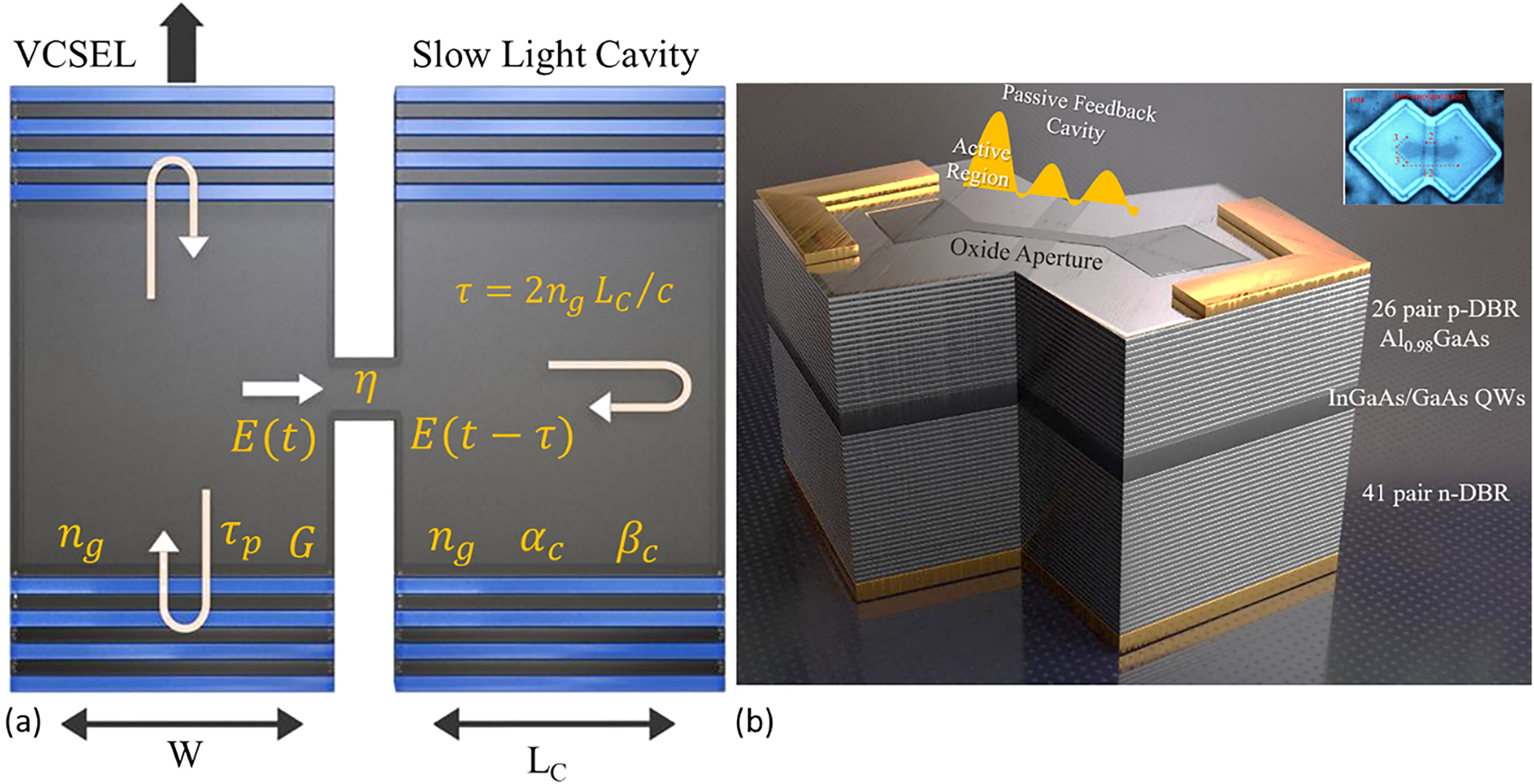
A scheme of slow-light feedback in VCSEL with a cascade of multiple TCCs.
The slow light then propagates with the group velocity of v
g = c/n
g
, where n
g
= fn is the group index, n is the average material refractive index, and f is the slow factor of light. Thus slow light is totally reflected back at the far end of the lateral waveguide and travels round trips in the cavity. After each round trip, the slow light is coupled to the primary VCSEL cavity through the oxide aperture. In each round trip in the TCC, the slow light suffers the loss of
Figure 3 depicts the proposed design and model of the MTTC-VCSEL, which shows a top view of the VCSEL surrounded in the lateral direction by multiple lossy cavities (arms) connected by oxide apertures. In the direction of each TCC, this coupled waveguide structure introduces a leaky traveling wave. In the laterally coupled waveguides, light travels perpendicularly and is slowing down. Within each TCC, the slow light propagates between the end of the TCC (arm) to the VCSEL cavity (at the device center) for a number of round trips with a group velocity of v
g. The slow light is totally reflected back at the corresponding aperture and is coupled into the VCSEL cavity with a coupling ratio η. The period of the round trip between the VCSEL cavity and the far end of the mth TCC is
which represents a generalized form of the gain derived in references [23, 26]. The OFB function U m (t − τ m ) is a time-delay function that describes the slow-light feedback from the mth TCC.
where the summation is over the multiple round trips in the TCC. In this case, θ(t − pτm) − θ(t) represents the deviation in the optical phase due to chirping in the mth cavity.
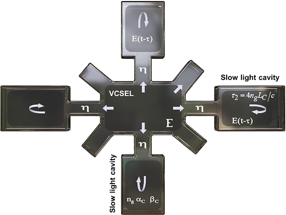
Schematic top-view of VCSEL with each of the multiple surrounding cavities providing direct slow-light feedback.
The rate equations of the MTCC-VCSEL are given for the injected electron number N(t), photon number S(t) contained in the lasing mode, and the optical phase
where a is the differential gain of the active region whose volume is V, N T is the electron number at transparency, and ε is the gain suppression coefficient. Γ is the confinement factor, τ p = 1/GthD is the photon lifetime, η i is the injection efficiency, τ s is the electron lifetime due to the spontaneous emission, R sp is the spontaneous emission rate, and N th is the electron number at the threshold. In Eq. (3), the injection current is assumed to have sinusoidal current modulation with bias component I b, modulation component I m, and modulation frequency f m.
The Langevin noise sources in Eqs. (3)–(5) are given in respective by [27]
where x
s
, x
N
, and x
θ
are random numbers having normal distributions with zero mean and variance of unity. The frequency content of intensity fluctuations is measured in terms of relative intensity noise (RIN), which is calculated from the fluctuations
where f is the Fourier frequency.
3 Numerical calculations
In the present calculations and for simplicity, we assume that the TCCs are identical, each TCC has length L C , group index n g, propagation constant β C , optical loss α C , and hence round trip τ. Also, the lateral slow-light is coupled to the primary VCSEL cavity with an equal coupling ratio η. Therefore, the threshold gain in Eq. (1) is reduced to
with the feedback function U(t − τ) id then given by
We integrate rate equation (3)–(5) by means of the fourth-order Runge–Kutta algorithm using a time step as short as Δt = 0.2 ps. The calculations of the time-delayed values of the photon number and phase are achieved as follows. In the time interval
The data samples for characterization of laser dynamics and noise are collected after the laser operation is stabilized. We apply the numerical values of the VCSEL parameters given in Table 1 [3]. The slow factor and material absorption loss are set to be f = 40 and α m = 10 cm−1, respectively, and the bias current is I b = 2 mA. For simulation of the IM response of the MTCC-VCSEL, we apply the fast Fourier transform (FFT) to the modulated laser signal as,
where a 1(f m) is the fundamental peak of the FFT spectrum of the laser intensity at the modulation frequency f m. In this calculation, we drop the noise sources in rate equations (3)–(5).
Definition and numerical values of the VCSEL parameters [3].
| Parameter | Value |
|---|---|
| Refractive index of active region n | 3.3 |
| Material loss of active region α m | 1000 m−1 |
| Slow factor f | 40 |
| Volume V | 1.76 × 10⁻¹⁹ m3 |
| Width of the VCSEL cavity W | 4 μm |
| Differential gain a | 3.64 × 10⁻¹² m3s−1 |
| Confinement factor Γ | 0.0382 |
| Electron number at transparency N T | 3.17 × 10⁵ |
| Gain suppression coefficient ε | 2.25 × 10⁻⁵ s−1 |
| Photon lifetime τ ph | 2 ps |
| Spontaneous emission rate R sp′ | 6.6 × 1028 m−3 s−1 |
| Material absorption α m | 10 m−1 |
| Injection efficiency η i | 0.6 |
| Electron lifetime τ s | 1.5 ns |
| Linewidth enhancement factor α | 2 |
4 Results and discussions
4.1 Modulation response of VCSEL with single TCC
Examples of the IM response spectra with improved MBW (f 3dB) of a VCSEL integrated with a single TCC are plotted in Figure 4. These spectra correspond to TCC length of L C = 5 μm and coupling ratio of η = 0.75, 0.8, and 0.9. The figure indicates an increase of MBW beyond that of the conventional VCSEL (C-VCSEL), f 3dB0 = 21.5 GHz, to f 3dB = 27.5, 36, and 40 GHz when η = 0.75, 0.8, and 0.9, respectively. This range of η corresponds to very strong transverse optical feedback. The increase of MBW can be attributed to the strong anti-phase coupling between the transverse coupled radiation and the vertically lasing radiation in the VCSEL cavity [20].
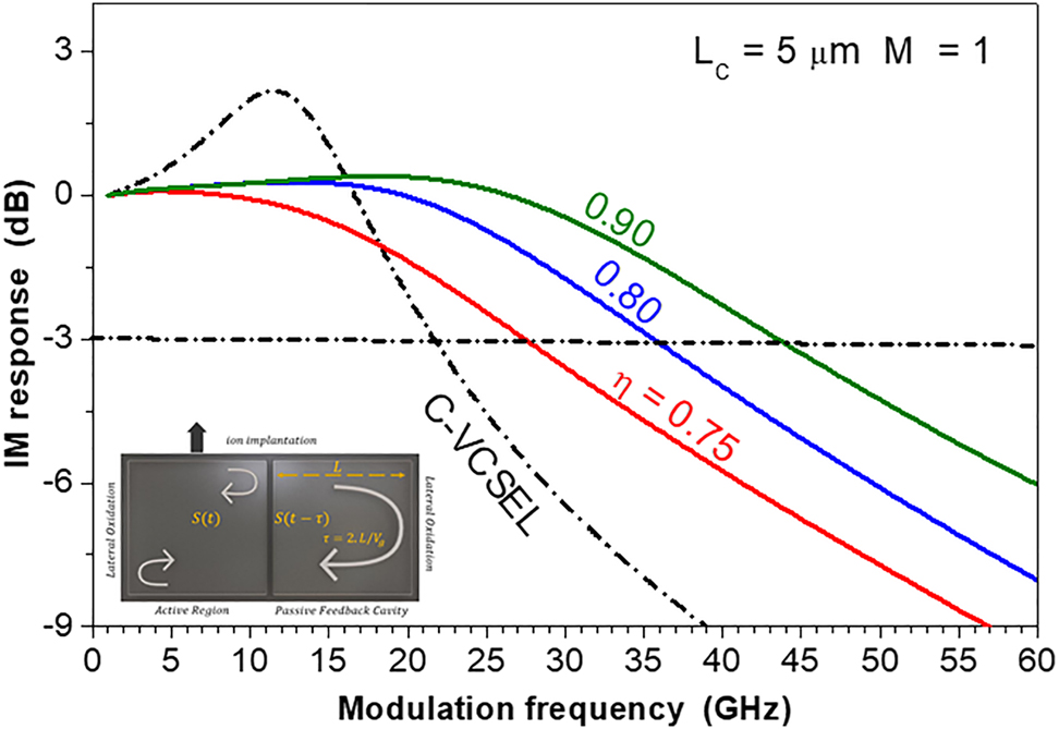
IM response with bandwidth improvement of the design of TCC VCSEL with L C = 5 μm when η = 0.75, 0.8, and 0.9. The IM response of the C-VCSEL is plotted for comparison with the dashed-dotted line.
The predicted values of MBW f 3dB are plotted as a function of the coupling ratio η in Figure 5 for TCC lengths of L C = 5 and 6 μm. The figure indicates the increase of f 3dB in the regime of very strong feedback with coupling ratios of η > 0.71 when L C = 5 μm and η > 0.78 when L C = 6 μm. The values of f 3dB are smaller when L C = 6 μm than those when L C = 5 μm since the strength of OFB decreases with the increase of the length of the feedback waveguide.
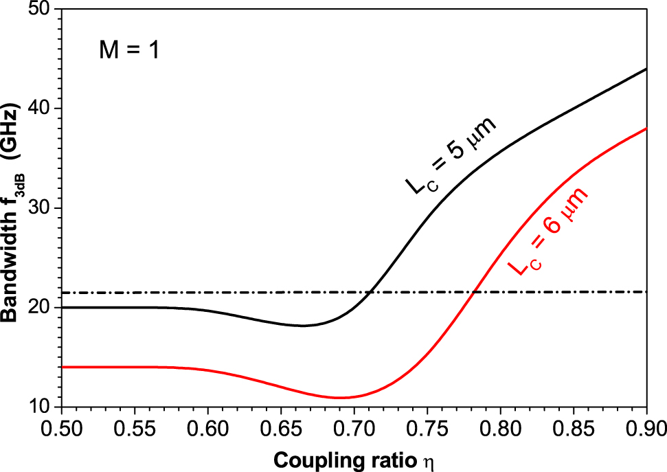
Variation of the bandwidth f 3dB of the TTC VCSEL with the coupling ratio η when L C = 5 and 6 μm.
4.2 Modulation response of MTCC-VCSEL
We show how increasing the number of lateral TCCs not only reduces the range of coupling that corresponds to an increase in MBW but also increases the bandwidth to much higher and more interesting levels. Figure 6(a)–(c) plot examples of the IM responses with MBW enhancement when the number of lateral TCCs increases to M = 2, 4, and 6, respectively. All cases correspond to the TCC length of L C = 5 μm. Figure 6(a) of M = 2 shows that the MBW values of f 3dB = 40 and 45 GHz are obtained when η = 0.4 and 0.5, respectively, which are almost one half the values in Figure 4 that results in the same MBW in the TCC-VCSEL. The bandwidth increases further to 60 and 61 GHz when the coupling ratio increases to η = 0.7 and 0.9, respectively. It is worth noting that a PPR effect is induced with the increase of η; a PPR peak is seen around the modulation frequency f PP = 180 GHz when η = 0.9. This PPR is a result of modulation at frequencies close to the beating frequencies of external cavity oscillating modes [14, 17, 18, 29, 30]. When the VCSEL is surrounded by 4TCCs (M = 4), Figure 6(b) shows that the low values of the coupling ratio of η = 0.2 and 0.3 accumulate more slow-light feedback in the VCSEL cavity so that the MBW is increased to f 3dB = 48 and 64, respectively. The PPR effect is remarkable when η = 0.5 which is seen as resonant modulation with a PPR peak of 5.8 dB around a very high frequency of f PP = 176 GHz. In this case, MBW is enhanced to f 3dB = 80 GHz. The further increase of the light coupling into the VCSEL cavity to η = 0.6 compensates the loss in the drop of the IM response under the −3 dB level and results in an ultra-high MBW of f 3dB = 170 GHz and a high PPR peak around f PP = 145 GHz. These values, to the best of our knowledge, are the highest predicted values for the semiconductor laser MBW. Figure 6(c) indicates more improvement of the modulation performance with higher values of MBW at lower values of the coupling ratio η when the number of TCCs increases to M = 6. At the low coupling of η = 0.15, MBW of the 6TTC-VCSEL is f 3dB = 56 GHz. The PPR effect is initiated at lower values of the coupling ratio; when η = 0.3 a PPR peak is seen around frequency f PP = 175 GHz. The associated MBW is f 3dB = 76 GHz. When η increases to 0.45, the PPR is too enhanced to reveal resonant modulation of 6.2 dB around frequency f PP = 165 GHz and the associated bandwidth of f 3dB = 85 GHz. In this case of 6TCC-VCSEL, the ultra-high MBW of f 3dB = 165 GHz is obtained at a lower coupling of η = 0.5, which is associated also with a higher PPR peak around f PP = 147 GHz.
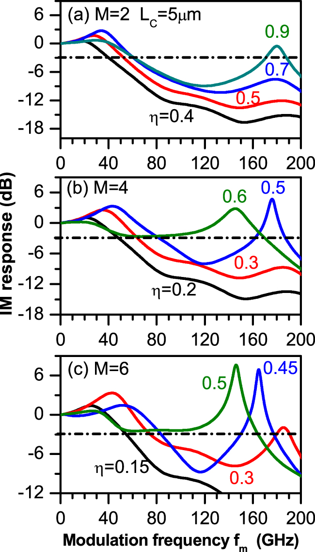
IM response of the design of (a) 2TCC-VCSEL, (b) 4TCC-VCSEL, and (c) 6TCC-VCSEL with L C = 5 μm at different values of η that results in MBW enhancement.
In Figure 7(a), we plot variation of MBW, f 3dB, with the coupling ratio η for the three cases of MTCC-VCSEL (M = 2, 4, and 6) when L C = 5 μm. The figure shows that the MBW improvement when M = 2 is initiated when η > 0.35 and f 3dB reaches 62 GHz when η > 0.75. In the case of the 4TCC VCSEL, MBW is much more enhanced when η > 0.15. When η > 0.4 the PPR effect is remarkable and MBW reaches f 3dB = 84 GHz when η = 0.64. In the range of 0.65 ≤ η ≤ 0.77, the strong light feedback works to recover the gap between the CPR and PPR peaks above the 3 dB level, and MBW is much more enhanced to values between f 3dB = 88 and f 3dB = 178 GHz. The BW improvement is achieved at weaker optical feedback coupling of η > 0.10 by the 6TTC-VCSEL. When η > 0.30, the boosted PPR effect is associated with enhanced MBW to values reaching f 3dB = 84 GHz. The further increase of η between 0.45 and 0.65 raises the IM response above the 3 dB level, which is smaller than the range achieved by the 4TTC-VCSEL. In this case, the predicted values of MBW are in the ultra-high frequency range of f 3dB = 88–180 GHz. The corresponding variations of f 3dB with η when L C = 6 μm are plotted in Figure 7(b). The figure shows that the behaviors of f 3dB with the variation of η for the three cases of M = 2, 4, and 6 are similar in general to those when L C = 5 μm. However, the increase of MBW of the MTCC-VCSEL above that of the C-VCSEL occurs at smaller values of the coupling ratio η, and the predicted bandwidth is lower. The highest MBW ranges between f 3dB = 80 and 155 GHz. It is worth reporting that when the TCC is shorter than 5 μm the laser operates under CW, and the slow-light feedback is coupled in such a way to make the frequency gap between the CPR and PPR peak lower than the 3 dB level, which then does not support MBW enhancement.
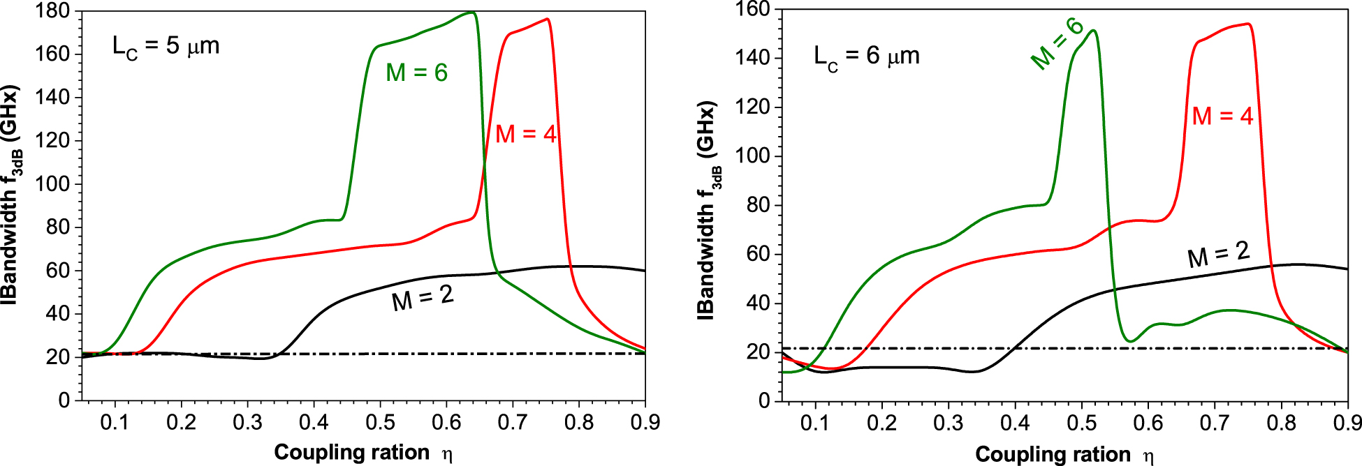
Variation of the bandwidth f 3dB of the TTC VCSEL with the coupling ratio η when (a) L C = 5 μm and (b) L C = 6 μm for 2TCC-VCSEL, 4TCC-VCSEL, and 6TCC-VCSEL.
4.3 Noise properties of MTTC VCSEL
In this subsection, we investigate the noise properties of the MTCC-VCSEL under current modulation. We focus on the regime of ultra-high bandwidth, f 3dB > 100 GHz, shown in Figure 7 for cases of VCSEL integrated with four TCCs (M = 4) and six TCCs (M = 6). The noise is evaluated in terms of the frequency spectrum of RIN when the MTCC-VCSEL is modulated with modulation frequency f m equal to one of the PPR frequencies in the regimes of ultra-high bandwidth. As explored in Figure 7, these regimes are 0.68 ≤ η ≤ 0.78 and 0.66 ≤ η ≤ 0.76 for 4TCC-VCSEL with L C = 5 and 6 μm, respectively, while they are 0.475 ≤ η ≤ 0.645 and 0.0.475 ≤ η ≤ 0.52 for 4TCC-VCSEL, respectively. Figure 8(a)–(d) plot four examples of the simulated RIN spectra of MTCC-VCSEL with L C = 5 μm when (M = 4, η = 0.7, f m = 145 GHz) and when (M = 6, η = 0.64, f m = 149 GHz), and of MTCC-VCSEL with L C = 6 μm when (M = 4, η = 0.76, f m = 129 GHz) and when (M = 6, η = 0.52, f m = 127 GHz), respectively. The figures show that the RIN spectra exhibit pronounced peaks around the modulation frequency f m due to the high degree of periodicity. At frequencies lower than the regime of the resonance peak, the RIN level increases in general with the decrease of frequency and then exhibits flat (white) noise in the regime of low frequencies f m < 1 GHz. The figures indicate also that the level of the low-frequency RIN (LF-RIN) of the 4TTC-VCSEL is almost one-order of magnitude lower than that of the 6TCC-VCSEL. This difference may indicate that the modulated signal of the 6TCC-VCSEL at this ultra-high frequency is a little more irregular than that of the 4TCC-VCSEL.
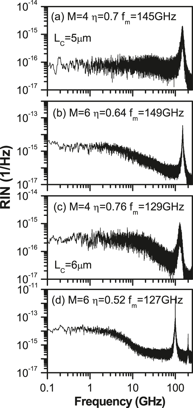
RIN spectra of MTCC-VCSEL with L C = 5 μm when (a) M = 4, η = 0.7, f m = 145 GH, (b) M = 6, η = 0.64, f m = 149 GHz, and of MTCC VCSEL with L C = 6 μm when (c) M = 4, η = 0.76, f m = 129 GHz, and (d) M = 6, η = 0.52, f m = 127 GHz.
In Figure 9(a) and (b), we compare variations of the LF-RIN level of the 4TCC-VCSEL and 6TCC-VCSEL, respectively, when the TCC length is L C = 5 and 6 μm. The figure indicates an increase of LF-RIN with the increase of the coupling ratio η in general. The noise levels when L C = 5 μm are comparable to those of the nonmodulated TCC VCSEL as investigated by Ibrahim et al. [27]. The figure shows also that the noise levels when L C = 6 μm are higher than those when L C = 5 μm. Finally, the noise levels in the 6TCC-VCSEL are almost one-order of magnitude higher than those in the 4TCC-VCSEL over the same range of slow-light feedback. However, the investigated ranges of LF-RIN of the MTTC-VCSEL are still much lower than the level >10−8 1/Hz that characterizes the unstable dynamics of the VCSEL [27].
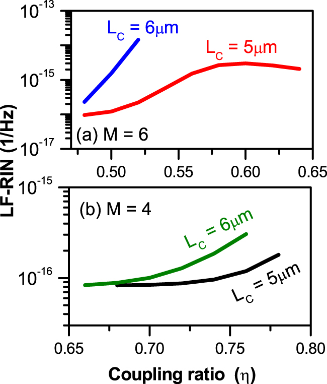
Variation of the LF-RIN level of (a) the 4TCC-VCSEL and (b) 6TCC-VCSELwhen the TCC length is L C = 5 and 6 μm.
Before concluding, we will briefly discuss this paper’s results in the wider context of advancements in nanophotonic emitters and lasers [31]. The interplay between the EM field, gain feedback, and laser performance is indeed forming an intricate system composed of the optical mode (or few-mode) cavities [32], [33], [34] and laser physics [35], [36], [37], [38], [39], [40], [41], [42], both at the nanoscale and (sub) diffraction-limited optical modes. Our work demonstrating enhanced laser modulating speed performance can also be seen as an extension of the ongoing discussion in the field of miniaturized laser devices. Here the debate around whether the Purcell factor, which captures the light–matter-interaction strength of such a laser cavity being proportional to the cold-cavities’ quality factor (Q) divided by the cavities’ mode volume, has (or has not) an influence on both the PPR and gain relaxation frequencies, i.e. speed of the laser [35], is an open debate to date. The Purcell factor is especially high in light emitters and lasers featuring a sub diffraction-limited optical mode, primarily due to the nonlinear scaling of volume and the introduced loss due to the cavities’ inability to provide OFB. This impacts the PPR in such small-volume cavities at (or below) the diffraction-limit of light [35], [36], [37], [38] because the laser design is also capable of increasing the temporal relaxations oscillations of the laser cavity. This in turn expands the “speed” of the laser under direct modulation. An example of this is the transverse-coupled cavity laser design that provides coherent feedback from a plurality of cavities and thus enhances the light emission from a central lasing cavity [24]. Looking ahead, future research should also investigate the effects of PPR in cavities with high longitudinal modes, for example in fiber optic-based laser systems for Brillouin amplification [43]. As it stands, the coherent feedback design of opportunely engineering a multiple TCC-based laser, as shown here, offers a new degree of freedom in laser and VCSEL design explorations. Given the predicted performance, these emerging VCSELs are poised to show a significant impact on the next-generation 5G and 6G network systems, data centers, and high-end sensors systems.
5 Conclusions
Finally, for the enhancement of MBW, potential designs and modeling of VCSEL encircled in the lateral direction by numerous TCCs were given. We demonstrated that the linked slow-light from each of the surrounding TCCs is collected in such a way that strong OFB is produced in the VCSEL cavity, outperforming VCSELs coupled with a single TCC or two TCCs. In VCSELs with four and six transverse cavities, this high feedback increases the PPR and MBW to about 150 GHz. The RIN spectrum is prominent around the modulation frequency, while the low-frequency portion is flat, with levels equivalent to nonmodulated TCC VCSELs.
Funding source: King Abdulaziz University
Award Identifier / Grant number: RG-18-130-41
Acknowledgment
The authors, therefore, acknowledge with thanks DSR technical and financial support.
-
Author contribution: All the authors have accepted responsibility for the entire content of this submitted manuscript and approved submission.
-
Research funding: This project was funded by the Deanship of Scientific Research (DSR) at King Abdulaziz University, Jeddah, under grant no. (RG-18-130-41).
-
Conflict of interest statement: The authors declare no conflicts of interest regarding this article.
References
[1] K. Iga, “Vertical-cavity surface-emitting laser: its conception and evolution,” Jpn. J. Appl. Phys., vol. 47, no. 1R, pp. 1–10, 2008. https://doi.org/10.1143/jjap.47.1.Suche in Google Scholar
[2] F. Koyama, “Recent advances of VCSEL photonics,” J. Lightwave Technol., vol. 24, no. 12, pp. 4502–4513, 2006. https://doi.org/10.1109/jlt.2006.886064.Suche in Google Scholar
[3] L. A. Coldren, S. W. Corzine, and M. L. Mashanovitch, Diode Lasers and Photonic Integrated Circuits, vol. 218, Hoboken, John Wiley & Son, 2012, p. 260.10.1002/9781118148167Suche in Google Scholar
[4] C. Wilmsen, H. Temkin, and L. A. Coldren, Vertical-cavity Surface- Emitting Lasers: Design, Fabrication, Characterization, and Applications, vol. 24, United Kingdom, Cambridge University Press, 2001.Suche in Google Scholar
[5] S. Kajiya, K. Ksukamoto, and S. Komaki, “Proposal of fiber-opticradio highway networks using CDMA method,” IEICE Trans. Electron., vols E79-C, no. 1, pp. 496–500, 1996.10.1109/ICUPC.1995.497058Suche in Google Scholar
[6] U. Feiste, “Optimization of modulation bandwidth of DBR lasers with detuned Bragg reflectors,” IEEE J. Quant. Electron., vol. 34, pp. 2371–2379, 1998. https://doi.org/10.1109/3.736110.Suche in Google Scholar
[7] R. Mindaugas, A. Glitzky, U. Bandelow, et al.., “Improving the modulation bandwidth in semiconductor lasers by passive feedback,” IEEE J. Sel. Top. Quant. Electron., vol. 13, pp. 136–142, 2007.10.1109/JSTQE.2006.885332Suche in Google Scholar
[8] K. H. Kao, N. M. Wang, and H. M. Chen, “Mode description of routes to chaos in external-cavity coupled semiconductor lasers,” IEEE J. Quant. Electron., vol. 30, pp. 1732–1739, 1994. https://doi.org/10.1109/3.301636.Suche in Google Scholar
[9] M. Ahmed, M. Yamada, and S. Abdulrhmann, “Numerical modeling of the route‐to‐chaos of semiconductor lasers under optical feedback and its dependence on the external‐cavity length,” Int. J. Numer. Model. Electron. Network. Dev. Field., vol. 22, pp. 434–445, 2009. https://doi.org/10.1002/jnm.719.Suche in Google Scholar
[10] S. Donati and R. Horng, “The diagram of feedback regimes revisited,” IEEE J. Sel. Top. Quant. Electron., vol. 19, 2013, Art no. 1500309. https://doi.org/10.1109/jstqe.2012.2234445.Suche in Google Scholar
[11] M. Ahmed, B. Ahmed, A. Ahmed, and H. Dali, “Use of external optical feedback to stabilize multimode hopping and reduce intensity noise in long-wavelength semiconductor laser,” Opt. Quant. Electron., vol. 53, pp. 1–17, 2021. https://doi.org/10.1007/s11082-021-02860-9.Suche in Google Scholar
[12] M. S. Alghamdi, H. Dalir, B. Ahmed, R. T. Chen, and M. Ahmed, “Regimes of bandwidth enhancement in coupled-cavity semiconductor-laser using photon-photon resonance,” Jpn. J. Appl. Phys., vol. 58, 2019, Art no. 112003. https://doi.org/10.7567/1347-4065/ab4979.Suche in Google Scholar
[13] M. Ahmed, “Modeling of generating ultra-high frequency oscillations in VCSEL integrated with cascaded transverse coupled cavities,” Appl. Phys. B, vol. 126, pp. 1–10, 2020. https://doi.org/10.1007/s00340-020-07520-6.Suche in Google Scholar
[14] H. Dalir, A. Matsutani, M. Ahmed, A. Bakry, and F. Koyama, “High frequency modulation of transverse-coupled-cavity VCSELs for radio over fiber applications,” IEEE Photon. Technol. Lett., vol. 26, no. 3, pp. 281–283, 2014. https://doi.org/10.1109/lpt.2013.2292577.Suche in Google Scholar
[15] M. S. Alghamdi, H. Dalir, B. Ahmed, R. T. Chen, and M. Ahmed, “Regimes of bandwidth enhancement in coupled-cavity semiconductor-laser using photon-photon resonance,” Jpn. J. Appl. Phys., vol. 58, 2019, Art no. 112003. https://doi.org/10.7567/1347-4065/ab4979.Suche in Google Scholar
[16] H. Dalir, A. Matsutani, M. Ahmed, A. Bakry, and F. Koyama, “High frequency modulation of transverse-coupled- cavity VCSELs for radio over fiber applications,” IEEE Photon. Technol. Lett., vol. 26, no. 3, pp. 281–283, 2014. https://doi.org/10.1109/lpt.2013.2292577.Suche in Google Scholar
[17] A. Paraskevopoulos, H. J. Hensel, W. D. Molzow, et al.., OFC Conference and the National Fiber Optic Engineers Conference, paper PDP22, 2006.Suche in Google Scholar
[18] C. Chen and K. D. Choquette, “Analog and digital functionalities of coupled cavity surface emitting lasers,” J. Lightwave Technol., vol. 28, pp. 1003–1010, 2010. https://doi.org/10.1109/jlt.2010.2041747.Suche in Google Scholar
[19] H. Dalir and F. Koyama, “Modulation bandwidth enhancement of VCSELs with lateral optical feedback of slow light,” in Proceedings of IEEE International Semiconductor Laser Conference, IEEE, 2010, pp. 83–84.10.1109/ISLC.2010.5642742Suche in Google Scholar
[20] H. Dalir and F. Koyamad, “Bandwidth enhancement of single-mode VCSEL with lateral optical feedback of slow light,” IEICE Electron. Express, vol. 8, no. 13, pp. 1075–1081, 2011. https://doi.org/10.1587/elex.8.1075.Suche in Google Scholar
[21] H. Dalir and F. Koyama, “29 GHz directly modulated 980 nm vertical-cavity surface emitting lasers with bow-tie shape transverse coupled cavity,” Appl. Phys. Lett., vol. 103, no. 9, 2013, Art no. 091109. https://doi.org/10.1063/1.4820149.Suche in Google Scholar
[22] H. Dalir and F. Koyama, “High speed operation of bow-tie-shaped oxide aperture VCSELs with photon-photon resonance,” Appl. Phys. Express, vol. 7, 2014, Art no. 022102. https://doi.org/10.7567/apex.7.022102.Suche in Google Scholar
[23] M. F. Ahmed, A. Bakry, R. Altuwirqi, M. S. Alghamdi, and F. Koyama, “Enhancing the modulation bandwidth of VCSELs to the millimeter-waveband using strong transverse slow-light feedback,” Opt Express, vol. 23, no. 7, pp. 15365–15371, 2015. https://doi.org/10.1364/OE.23.015365.Suche in Google Scholar PubMed
[24] E. Heidari, H. Dalir, M. Ahmed, V. J. Sorger, and R. Chen, “Hexagonal transverse-coupled-cavity VCSEL redefining the high-speed lasers,” Nanophotonics, vol. 9, pp. 4743–4748, 2020. https://doi.org/10.1515/nanoph-2020-0437.Suche in Google Scholar
[25] M. Ahmed, H. Dalir, and R. Chen, “Optical devices with transverse-coupled cavity,” Patent US010658815B1, USA Patent and Trademark Office, 2020.Suche in Google Scholar
[26] R. Lang and K. Kobayashi, “External optical feedback effects on semiconductor injection laser properties,” IEEE J. Quant. Electron., vol. 16, no. 3, pp. 347–355, 1980. https://doi.org/10.1109/jqe.1980.1070479.Suche in Google Scholar
[27] H. R. Ibrahim, M. S. Alghamdi, B. Ahmed, M. Ahmed, and F. Koyama, “Modelling and characterisation of the noise characteristics of the vertical cavity surface-emitting lasers subject to slow light feedback,” Pramana - J. Phys., vol. 93, no. 73, p. 7, 2019. https://doi.org/10.1007/s12043-019-1831-2.Suche in Google Scholar
[28] M. Ahmed, M. Yamada, and M. Saito, “Numerical modeling of intensity and phase noise in semiconductor lasers,” IEEE J. Quant. Electron., vol. 37, p. 1600, 2001. https://doi.org/10.1109/3.970907.Suche in Google Scholar
[29] P. Westbergh, J. S. Gustavsson, B. Kögel, Å. Haglund, and A. Larsson, “Impact of photon lifetime on high-speed VCSEL performance,” IEEE J. Sel. Top. Quantum Electron., vol. 17, pp. 1603–1613, 2011. https://doi.org/10.1109/jstqe.2011.2114642.Suche in Google Scholar
[30] P. Bardella, W. Chow, and I. Montrosset, “Design and analysis of enhanced modulation response in integrated coupled cavities DBR lasers using photon-photon resonance,” Photon, vol. 3, pp. 1–14, 2016. https://doi.org/10.3390/photonics3010004.Suche in Google Scholar
[31] A. Fratalocchi, C. M. Dodson, R. Zia, et al.., “Nano-optics gets practical,” Nat. Nanotechnol., vol. 10, pp. 11–15, 2015. https://doi.org/10.1038/nnano.2014.314.Suche in Google Scholar PubMed
[32] V. J. Sorger, R. F. Oulton, J. Yao, G. Bartal, and X. Zhang, “Fabry-Perot Plasmonic Nanocavity,” Nano Lett., vol. 9, 2009, pp. 3489–3493. https://doi.org/10.1021/nl901682n.Suche in Google Scholar PubMed
[33] B. Min, E. Ostby, V. J. Sorger, et al.., “High-Q surface plasmon-polariton whispering-gallery microcavity,” Nature, vol. 457, pp. 455–458, 2009. https://doi.org/10.1038/nature07627.Suche in Google Scholar PubMed
[34] K. Liu, N. Li, D. K. Sadana, and V. J. Sorger, “Integrated nano-cavity plasmon light-sources for on-chip optical interconnects,” ACS Photonics, vol. 3, pp. 233–242, 2016. https://doi.org/10.1021/acsphotonics.5b00476.Suche in Google Scholar
[35] R. F. Oulton, V. J. Sorger, T. Zentgraf, et al.., “Plasmon lasers at deep subwavelength scale,” Nature, vol. 461, pp. 629–631, 2009. https://doi.org/10.1038/nature08364.Suche in Google Scholar PubMed
[36] R.-M. Ma, R. F. Oulton, V. J. Sorger, and X. Zhang, “Room-temperature sub-diffraction-limited plasmon laser by total internal reflection,” Nat. Mater., vol. 10, pp. 110–113, 2010. https://doi.org/10.1038/nmat2919.Suche in Google Scholar PubMed
[37] R.-M. Ma, R. F. Oulton, V. J. Sorger, and X. Zhang, “Plasmon lasers: coherent light source at molecular scales,” Laser Photon. Rev., vol. 7, pp. 1–21, 2012. https://doi.org/10.1002/lpor.201100040.Suche in Google Scholar
[38] R.-M. Ma, X. Yin, R. F. Oulton, V. J. Sorger, and X. Zhang, “Multiplexed and electrically modulated plasmon laser circuit,” Nano Lett., vol. 12, pp. 5396–5402, 2012. https://doi.org/10.1021/nl302809a.Suche in Google Scholar PubMed
[39] N. Li, K. Liu, V. J. Sorger, and D. K. Sadana, “Monolithic III-V on silicon nanolaser structure for optical interconnects,” Sci. Rep., vol. 5, p. 14067, 2015. https://doi.org/10.1038/srep14067.Suche in Google Scholar PubMed PubMed Central
[40] V. J. Sorger, “2D material nanowatt threshold lasing,” Nat. Mater., vol. 7, 2015, Art no. e200. https://doi.org/10.1038/am.2015.69.Suche in Google Scholar
[41] K. Liu and V. J. Sorger, “Electrically-driven carbon nanotube-based plasmonic laser on silicon,” Opt. Mater. Express, vol. 5, pp. 1910–1919, 2015. https://doi.org/10.1364/ome.5.001910.Suche in Google Scholar
[42] K. Liu, S. Sun, A. Majumdar, and V. J. Sorger, “Fundamental scaling laws in nanophotonics,” Sci. Rep., vol. 6, p. 37419, 2016. https://doi.org/10.1038/srep37419.Suche in Google Scholar PubMed PubMed Central
[43] F. S. Gokhan, H. Goktas, and V. J. Sorger, “Analytical approach of Brillouin amplification over threshold,” Appl. Opt., vol. 57, pp. 607–611, 2018. https://doi.org/10.1364/ao.57.000607.Suche in Google Scholar
© 2021 Elham Heidari et al., published by De Gruyter, Berlin/Boston
This work is licensed under the Creative Commons Attribution 4.0 International License.
Artikel in diesem Heft
- Frontmatter
- Editorial
- A tribute to Mark Stockman
- Perspectives
- Plasmons compressing the light – a jewel in the treasure chest of Mark Stockman’s legacy
- Novel non-plasmonic nanolasers empowered by topology and interference effects
- Nanofocusing: reaching out
- Spaser or plasmonic nanolaser? – Reminiscences of discussions and arguments with Mark Stockman
- Plasmonic nanolasers: fundamental properties and applications
- Research Articles
- Space- and time-resolved second harmonic spectroscopy of coupled plasmonic nanocavities
- Surface-response functions obtained from equilibrium electron-density profiles
- Effect of nanoscale dielectric environments on concentration quenching
- Optical spin–orbit coupling in the presence of magnetization: photonic skyrmion interaction with magnetic domains
- Anomalous ultrafast all-optical Hall effect in gapped graphene
- Exploiting space-time duality in the synthesis of impedance transformers via temporal metamaterials
- Optical current generation in graphene: CEP control vs. ω + 2ω control
- Edge detection with meta-lens: from one dimension to three dimensions
- Coherent control at gold needle tips approaching the strong-field regime
- Tailoring exceptional points in a hybrid PT-symmetric and anti-PT-symmetric scattering system
- Transition to strong coupling regime in hybrid plasmonic systems: exciton-induced transparency and Fano interference
- Single-nanoantenna driven nanoscale control of the VO2 insulator to metal transition
- High laser induced damage threshold photoresists for nano-imprint and 3D multi-photon lithography
- Onset of charge interaction in strong-field photoemission from nanometric needle tips
- Massive surface-plasmon polaritons
- VCSEL with multi-transverse cavities with bandwidth beyond 100 GHz