Transition to strong coupling regime in hybrid plasmonic systems: exciton-induced transparency and Fano interference
-
Tigran V. Shahbazyan


Abstract
We present a microscopic model describing the transition to a strong coupling regime for an emitter resonantly coupled to a surface plasmon in a metal–dielectric structure. We demonstrate that the shape of scattering spectra is determined by an interplay of two distinct mechanisms. First is the near-field coupling between the emitter and the plasmon mode which underpins energy exchange between the system components and gives rise to exciton-induced transparency minimum in scattering spectra prior to the transition to a strong coupling regime. The second mechanism is the Fano interference between the plasmon dipole and the plasmon-induced emitter’s dipole as the system interacts with the radiation field. We show that the Fano interference can strongly affect the overall shape of scattering spectra, leading to the inversion of spectral asymmetry that was recently reported in the experiment.
1 Introduction
Strong coupling between surface plasmons in metal–dielectric structures and excitons in semiconductors or dye molecules has recently attracted intense interest driven to a large extent by possible applications in ultrafast reversible switching [1–3], quantum computing [4, 5], and light harvesting [6]. In the strong coupling regime, the coherent energy exchange between excitons and plasmons [7] leads to the emergence of mixed polaritonic states with energy bands separated by the anticrossing gap (Rabi splitting) [8]. For excitons coupled to cavity modes in microcavities, the Rabi splitting magnitudes are relatively small on the scale of several meV [9–11]. However, in hybrid plasmonic systems, where surface plasmons are coupled to excitons in J-aggregates [12–22], in various dye molecules [23–27], or in semiconductor nanostructures [28–31], the Rabi splittings can be much greater even reaching hundreds meV. For single excitons, however, achieving a strong exciton–plasmon coupling is a challenging task as it requires extremely small plasmon mode volumes, which can mainly be achieved in nanogaps [32–34].
At the same time, the scattering spectra of hybrid plasmonic systems, such as excitons in J-aggregates or colloidal QDs coupled to gap plasmons in nanoparticle-on-metal systems [35–38] or those in two-dimensional atomic crystals conjugated with Ag or Au nanostructures [39–44], exhibit a narrow minimum even before reaching the strong coupling transition point. The emergence of such a minimum in the weak coupling regime is referred to as exciton-induced transparency (ExIT) [45–47], in analogy to electromagnetically induced transparency (EIT) in pumped three-level atomic systems that is attributed to the Fano interference between different excitation pathways. Recently, we have shown that, in the linear regime (i.e. in the absence of pump), the emergence of this minimum is due to the imbalance of energy exchange between the emitter and plasmon in a narrow frequency interval [48]. Typically, the plasmon optical dipole moment significantly (by ∼104) exceeds that of an exciton in a semiconductor quantum dot and so the emitter’s direct interaction with the radiation field is relatively weak [49]. In this case, the ExIT minimum in scattering spectra is described, with reasonably good accuracy, by the dressed plasmon model or by its classical analog – the coupled oscillators model, in which only the plasmon interacts with the radiation field, so that the scattering spectra show a narrow ExIT minimum on top of a broad plasmon band, while the overall spectral weight is tilted toward the higher frequency range [38, 47, 48].
On the other hand, in hybrid plasmonic systems, the optical interference between an exciton and a plasmon can arise from the indirect coupling of the exciton to the radiation field. Namely, if the incident light frequency is tuned to the plasmon resonance, the exciton dipole moment induced by the plasmon near field is not necessarily small, so that the exciton can substantially contribute, albeit indirectly, to the system optical transition. This gives rise to Fano interference between the plasmon and plasmon-induced exciton dipoles which can significantly affect the overall shape of optical spectra. As we show in this paper, such Fano interference effects can lead to inversion of spectral asymmetry, characterized by spectral weight shift toward lower frequency range, which was observed for excitons coupled to localized plasmon modes [22, 39, 40].
In this paper, we present a microscopic model for the linear optical response of a single exciton resonantly coupled to a surface plasmon mode in a metal–dielectric structure which accounts for both ExIT and Fano interference effects as the system transitions to a strong coupling regime. Starting with the canonical Hamiltonian with microscopic coupling parameters [50], we set up the system of Maxwell–Bloch equations for induced dipole moments which determine the scattering spectrum of the hybrid plasmonic system. We further show that while the ExIT minimum results from the energy exchange imbalance in a narrow frequency interval, the overall spectral shape of scattering spectra is strongly affected by the Fano interference between radiating plasmon and plasmon-induced exciton dipoles. Specifically, we demonstrate that the Fano interference can lead to an inversion of spectral asymmetry, consistent with the experiment [22, 39, 40].
2 The system Hamiltonian and microscopic coupling parameters
We consider a quantum emitter (QE) with dipole moment μ e and excitation frequency ω e situated at a position r e near a metal–dielectric structure characterized by complex dielectric function ɛ(ω, r ) = ɛ′(ω, r ) + iɛ″(ω, r ) supporting localized plasmon modes with frequencies ω m interacting with external electromagnetic (EM) field E (t). For monochromatic EM field of frequency ω, in the rotating wave approximation (RWA), the system dynamics is described by the Hamiltonian
where
For plasmonic nanostructures with characteristic size smaller than the radiation wavelength, the coupling parameters can be obtained microscopically by relating them to system geometry and local field [50]. For such systems, the plasmon modes are determined by the quasistatic Gauss equation [51]
The Gauss’s equation does not determine the overall field normalization [51], but the later can be found by matching the plasmon radiative decay rate and that of a localized dipole with excitation energy ℏω
m. The plasmon radiative decay rate has the form [52]
is the plasmon mode energy [53, 54] and
is the radiated power (c is the speed of light) [8]. The normalized modes
where μ m is the mode optical transition matrix element. We then find the normalization relation as
where the scaling factor
In a similar way, the plasmon nonradiative decay rate is
and so the plasmon full decay rate is
where we kept only the resonance term [52].
The QE–plasmon coupling in the Hamiltonian (1) is expressed via normalized plasmon mode fields as [50]
To present the coupling in a cavity-like form, we use the original plasmon mode fields (6) to obtain [7]
where
where Q
m = ω
m/γ
m is the plasmon quality factor,
Comparing Eqs. (11) and (13), we obtain a relation between the QE–plasmon coupling and decay rates:
Thus, all coupling parameters in the Hamiltonian characterizing plasmon interactions with the QE and EM fields are expressed via system parameters and related to plasmon and QE decay rates. Below, we employ these microscopic expressions to elucidate the role of ExIT and Fano interference in scattering spectra of hybrid plasmonic systems.
3 Optical dipole moment of a hybrid plasmonic system
We are interested in the linear response of hybrid plasmonic system to the external EM field. We assume that there is only a single excitation in the system and disregard any nonlinear effects. In this case, we can approximate the QE by bosonic operators to setup Maxwell–Bloch equations for nondiagonal elements of density matrix (polarizations) ρ e(t) and ρ m(t) related to QE and plasmon induced dipoles as p e(t) = μ e ρ e(t) and p m(t) = μ m ρ m(t), respectively. Using the Hamiltonian (1), in the linear approximation, the Maxwell–Bloch equations for ρ m(t) and ρ e(t) are obtained in a standard manner as
where dot stands for the time-derivative and γ e is the QE spectral linewidth assumed much smaller than γ m.
In the steady-state case, substituting ρ m(t) = ρ me−iωt and ρ e(t) = ρ ee−iωt , we find
and
The system’s induced dipole moment is p s = p m + p e = μ m ρ m + μ e ρ e. To elucidate the processes contributing to p s, we define QE polarizability tensor (in RWA) as
and introduce plasmon-induced QE dipole moment as
Then, the hybrid system dipole moment can be decomposed into three contributions:
The main contribution comes from the dressed plasmon characterized by induced dipole moment
where
is the plasmon’s self-energy due to its interactions with the QE. Specifically, the imaginary part of the self-energy determines the ET rate from the plasmon to QE as
which represents a Lorentzian centered at QE frequency ω e and maximum value γ m→e ≡ γ m→e(ω e) = 4g 2/γ e.
The QE–plasmon interference term has the form
and describes indirect, i.e. mediated by plasmon, interactions of QE with the EM field. The last term represents dressed QE contribution,
where
is the QE self-energy, whose imaginary part now determines the ET rate from the QE to plasmon as
which represents a Lorentzian centered at plasmon frequency ω m and maximum value γ e→m ≡ γ e→m(ω m) = 4g 2/γ m, matching Eq. (14). Importantly, in a narrow frequency interval |ω − ω e| ≲ γ e, the reverse plasmon–QE ET rate γ m→e exceeds the direct QE–plasmon ET rate γ e→m:
While the overall ET balance over the entire frequency range is preserved, the ET imbalance in the frequency interval ∼γ e leads to the emergence of the ExIT minimum in the dressed plasmon spectra [48]. For a typical case μ e/μ m ≪ 1, the dressed emitter’s dipole moment (25) is negligibly small relative to dressed plasmon’s dipole moment (21) and can be omitted. While the position and magnitude of the ExIT minimum are accurately described by this energy exchange mechanism within dressed plasmon approximation, i.e. p s ≈ p dp, it does not include QE interactions with the EM field. The latter is included indirectly in the interference term (24) via plasmon-induced QE dipole moment q e, which as we show below, gives rise to Fano interference that strongly affects the overall shape of scattering spectra as the system transitions to a strong coupling regime.
4 Exciton-induced transparency vs. Fano interference
The scattering cross-section
where ω
F
= −2gμ
e/μ
m is QE frequency shift due to Fano interference between the plasmon and plasmon-induced QE dipole moments as the system interacts with the EM field. In fact, this shift is the only difference between the current model and dressed plasmon model (with
where F(ω) is the Fano function,
Here, δ = 2(ω − ω e)/γ e is frequency detuning in units of linewidth and q is the Fano parameter:
The Fano function has asymmetric shape that depends on the sign of parameter q. Using Eq. (14), the magnitude of q can be expressed via the Purcell factor as
where
To elucidate the interplay between Fano interference and ExIT, we recall that in the scattering spectra, the ExIT minimum emerges in the weak coupling regime as a narrow dip on the top of a wide plasmon band. The plasmon scattering cross-section is obtained by setting g = 0 in Eq. (29) and, for μ m∥ E , has the form
To trace the emergence of ExIT minimum, we recast the dressed plasmon scattering cross-section as
modulates the plasmon band, and so the system scattering cross-section is factorized as
In the frequency interval |ω m − ω|/γ m ≪ 1, using the relation (14), the function R(ω) simplifies to
where the parameter
characterizes the ExIT minimum depth. The ExIT function (37) describes the emergence of spectral minimum due to excessively large plasmon–QE ET in the frequency interval ∼γ e. Specifically, in the weak coupling regime, the dressed plasmon decay rate has the form γ dp(ω) = γ m + γ m→e(ω). Using Eq. (23) and the relation (14), we obtain
implying linewidth increase by factor (1 + p) in the frequency interval |ω − ω e| ∼ γ e which, in turn, leads to the ExIT minimum in the dressed plasmon spectrum.
Thus, in the weak coupling regime, the ExIT and Fano interference effects are distinct and described by different factors in the scattering cross-section (36). While the ExIT factor R(ω) leads to a narrow minimum at the QE frequency position, the Fano factor F(ω) is an asymmetric function of ω that affects the overall shape of the scattering spectra. Remarkably, as we show in numerical calculations below, the Fano interference effect is most visible for intermediate and strong QE–plasmon coupling as it shifts the spectral weight between polaritonic bands resulting in the inversion of spectral asymmetry.
5 Numerical results and discussion
In this section, we present the results of numerical calculations for a QE situated at a distance d from the tip of an Au nanorod in water with excitation frequency in resonance with the surface plasmon frequency, ω
e = ωm
. The nanorod was modeled by a prolate spheroid with semi-major and semi-minor axes a and b, respectively, the QE’s dipole orientation was chosen along the nanorod symmetry axis, the Au experimental dielectric function was used in all calculations [56], and the dielectric constant of water was taken as ɛ
s = 1.77. We used the standard spherical harmonics for calculations of the local fields near the prolate spheroid to obtain the plasmon parameters μ
m, γ
m, η
m, the QE–plasmon coupling g, and the Purcell factor F
p, which determine the ExIT parameter p and Fano parameter q. The QE spectral linewidth γ
e was chosen much smaller than the plasmon decay rate, γ
e/γ
m = 0.1, and its radiative decay time was chosen
In Figure 1, we plot the calculated ExIT parameter p, given by Eq. (38), and the Fano parameter q, given by Eq. (32), against the distance to nanorod tip d normalized by a. Figure 1(a) shows the ExIT parameter
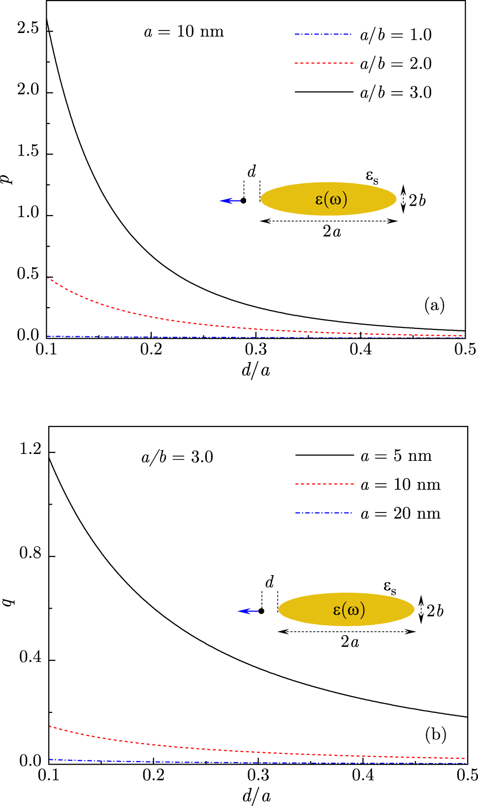
(a) The ExIT parameter p is plotted against the QE distance d to the tip of Au nanorod of length 2a = 20 nm placed for different values of aspect ratio a/b = 1.0, 2.0, and 3.0. (b) The Fano parameter q is plotted against the distance d at nanorod aspect ratio a/b = 3.0 for different values of nanorod length 2a = 40, 20, and 10 nm. Inset: schematics of a QE situated at a distance d from the tip of Au nanorod in water for QE dipole moment oriented along the nanorod axis.
In Figure 2, in order to illustrate the emergence of ExIT, we show the evolution of function R(ω), given by Eq. (35), and of dressed plasmon’s scattering cross-section
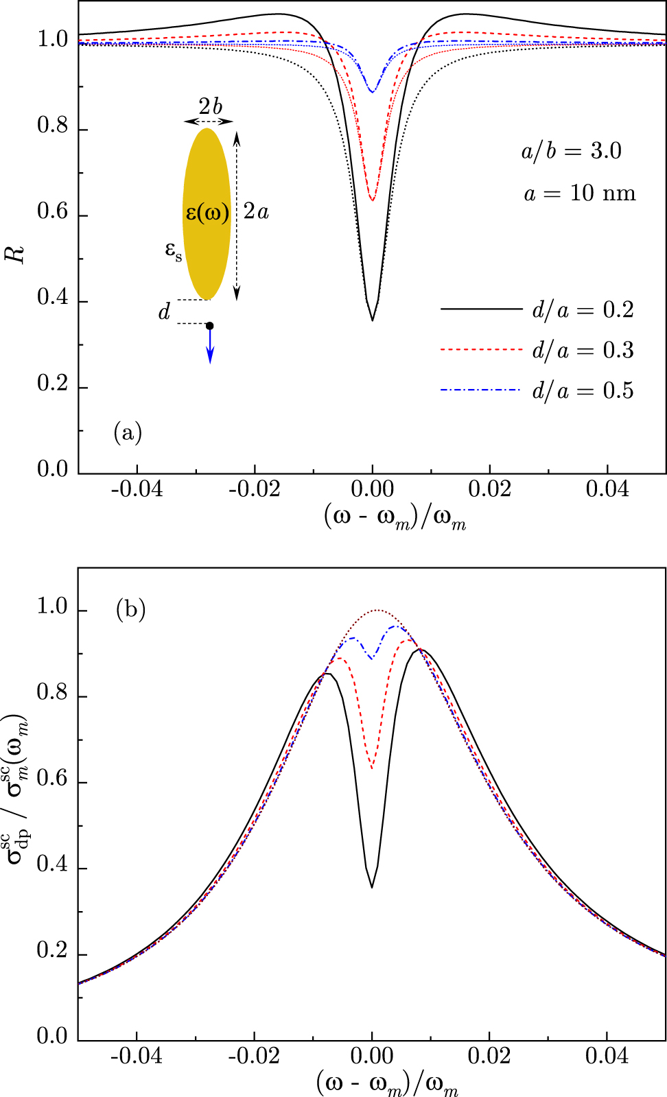
(a) The ExIT function R(ω), given by Eq. (35), and its asymptotic expression (dotted lines), given by Eq. (37), are shown for a QE near the tip of Au nanorod with aspect ratio a/b = 3.0 and length 2a = 20 nm at distances d/a = 0.5, 0.3, and 0.2. (b) Normalized scattering cross-section in the dressed plasmon approximation is shown for the same system parameters. The dotted line is the plasmon band. All curves are calculated for ω e = ω m. Inset: schematics of a QE situated at a distance d from the tip of Au nanorod in water for QE dipole moment oriented along the nanorod axis.
While the dressed plasmon model describes the position and depth of ExIT minimum relatively well, it predicts a sustained asymmetry as the higher frequency region of scattering spectrum carries a larger spectral weight [see Figure 2(b)]. In the absence of QE coupling to the EM field, emission takes place from the plasmonic antenna, whose power spectrum is ∝ω 4 due to a larger radiation rate at higher frequencies. Therefore, in the presence of double-peak structure due to either ExIT minimum or Rabi splitting centered at resonance frequency ω = ω m = ω e, the higher frequency peak is enhanced. Note that similar scattering spectra are predicted by the classical model of coupled oscillators which disregards optical interference effects [38, 47]. Below we demonstrate that extending the dressed plasmon model to include Fano interference between the plasmon antenna and plasmon-induced QE dipole, as described in Eq. (36), can strongly affect the overall shape of scattering spectra.
In Figure 3, we plot the Fano function and scattering spectra for a QE situated at several distances from the tip of Au nanorod with aspect ratio a/b = 3.0 and overall length 2a = 20 nm. As indicated above, we consider the case of QE’s dipole moment oriented along the normal to tip surface (see inset in Figure 3), so that the Fano parameter q is positive. For nanorod of this length, q is relatively small [see Figure 1(b)] and so the Fano function’s variation ranges from about 2% for d = 4 nm to 15% for d = 1 nm, as the QE–plasmon coupling g increases close to the tip [see Figure 3(a)]. Importantly, for q > 0, the spectral shape of the Fano function, which enters in the scattering cross-section (36), leads to the suppression of higher frequency region and enhancement of lower frequency region. As a result, the aforementioned asymmetry of dressed plasmon scattering spectra in Figure 2(b) is largely compensated, and so the full scattering spectra are now close to symmetric [see Figure 3(b)].
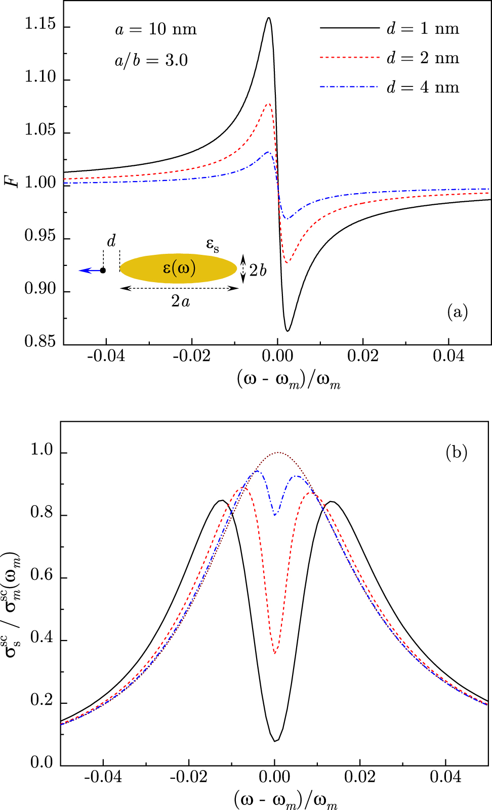
(a) The Fano function F(ω), given by Eq. (31), is shown for a QE near the tip of Au nanorod with aspect ratio a/b = 3.0 and length 2a = 20 nm at distances d= 4, 2, and 1 nm. (b) Normalized scattering cross-section, given by Eq. (36), is shown for the same system parameters. The dotted line is the plasmon band. All curves are calculated for ω e = ω m. Inset: schematics of a QE situated at a distance d from the tip of Au nanorod in water for QE dipole moment oriented along the nanorod axis.
In Figure 4, we show the Fano function and scattering spectra for a small nanorod of length 10 nm. With decreasing nanostructure size and, hence, the reduction of plasmon mode volume, the QE–plasmon coupling increases and so does the Fano parameter q, which now reaches values q ∼ 1 [see Figure 1(b)]. In this case, the Fano function variation is larger as well, reaching about 80% close to the nanorod tip [see Figure 4(a)]. As a result, the scattering spectra, shown in Figure 4(b), exhibit inversion of spectral asymmetry relative to the dressed plasmon spectra [see Figure 2(b)], with the lower frequency peak now substantially higher than the higher frequency peak. Note that for the smallest d, the system has clearly transitioned to a strong coupling regime since the double-peak structure is well beyond the plasmon spectral envelope. We stress that although the mechanisms of ExIT and Fano interference are distinct, as discussed in the previous section, the two effects are intimately related as Fano interference manifests itself via redistribution of spectral weight across the ExiT minimum in the scattering spectra.
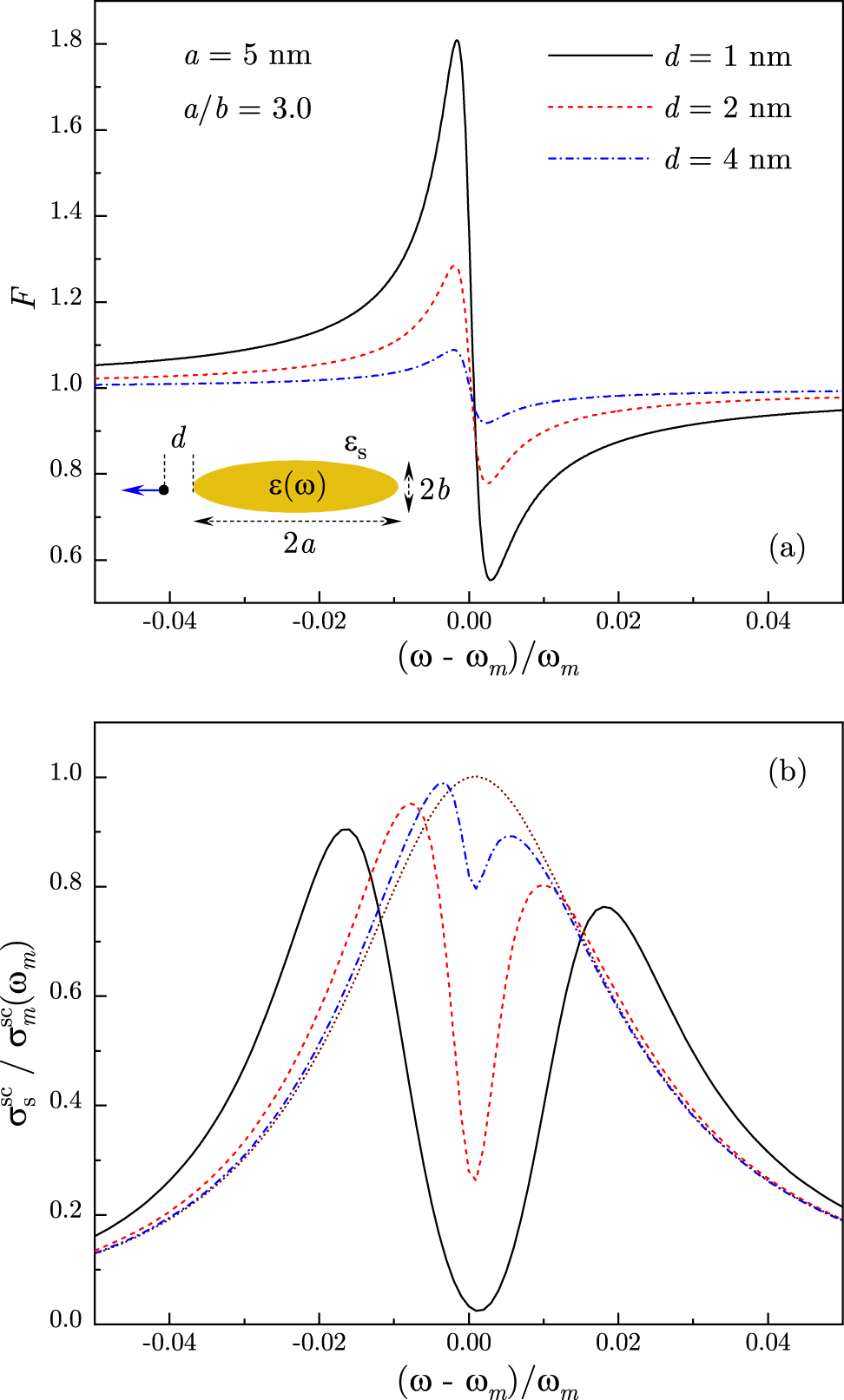
(a) The Fano function F(ω), given by Eq. (31), is shown for a QE near the tip of Au nanorod with aspect ratio a/b = 3.0 and length 2a = 10 nm at distances d = 4, 2, and 1 nm. (b) Normalized scattering cross-section, given by Eq. (36), is shown for the same system parameters. The dotted line is the plasmon band. All curves are calculated for ω e = ω m. Inset: schematics of a QE situated at a distance d from the tip of Au nanorod in water for QE dipole moment oriented along the nanorod axis.
6 Conclusions
In this paper, we developed a model for ExIT and Fano interference in hybrid plasmonic systems comprised a single emitter resonantly coupled to a surface plasmon in a metal–dielectric structure. We have shown that the shape of scattering spectra is determined by two distinct mechanisms. First is near-field coupling between the emitter and plasmon that defines the energy spectrum of the hybrid system. This mechanism relies upon energy exchange between the system components and gives rise to the ExIT minimum in scattering spectra and, in the strong coupling regime, to the Rabi splitting of polaritonic bands. The second mechanism is the Fano interference between the plasmon and the plasmon-induced emitter’s dipoles as the system interacts with the radiation field. Although the Fano interference does not significantly affect the position or magnitude of ExIT minimum, it determines the overall shape of scattering spectra. Specifically, the Fano interference leads to the inversion of spectral asymmetry that was recently reported in the experiment [22, 39, 40].
Funding source: Division of Materials Research
Award Identifier / Grant number: DMR-1826886
Award Identifier / Grant number: DMR-1856515
Award Identifier / Grant number: DMR-2000170
-
Author contribution: The author has accepted responsibility for the entire content of this submitted manuscript and approved submission.
-
Research funding: This work was supported in part by the National Science Foundation Grant Nos. DMR-2000170, DMR-1856515, and DMR-1826886.
-
Conflict of interest statement: The author declares no conflicts of interest regarding this article.
References
[1] T. Schwartz, J. A. Hutchison, C. Genet, and T. W. Ebbesen, “Reversible switching of ultrastrong light-molecule coupling,” Phys. Rev. Lett., vol. 106, p. 196405, 2011. https://doi.org/10.1103/physrevlett.106.196405.Search in Google Scholar
[2] A.-L. Baudrion, A. Perron, A. Veltri, A. Bouhelier, P.-M. Adam, and R. Bachelot, “Reversible strong coupling in silver nanoparticle arrays using photochromic molecules,” Nano Lett., vol. 13, pp. 282–286, 2013. https://doi.org/10.1021/nl3040948.Search in Google Scholar PubMed
[3] L. Lin, M. Wang, X. Wei, X. Peng, C. Xie, and Y. Zheng, “Photoswitchable Rabi splitting in hybrid plasmon-waveguide modes,” Nano Lett., vol. 16, pp. 7655–7663, 2016. https://doi.org/10.1021/acs.nanolett.6b03702.Search in Google Scholar PubMed
[4] S. Sun, H. Kim, G. S. Solomon, and E. Waks, “A quantum phase switch between a single solid-state spin and a photon,” Nat. Nanotechnol., vol. 11, pp. 539–544, 2016. https://doi.org/10.1038/nnano.2015.334.Search in Google Scholar PubMed
[5] L. De Santis, C. Anton, B. Reznychenko, et al.., “A solid-state single-photon filter,” Nat. Nanotechnol., vol. 12, pp. 663–667, 2017. https://doi.org/10.1038/nnano.2017.85.Search in Google Scholar PubMed
[6] A. Tsargorodska, M. L. Cartron, C. Vasilev, et al.., “Strong coupling of localized surface plasmons to excitons in light-harvesting complexes,” Nano Lett., vol. 16, pp. 6850–6856, 2016. https://doi.org/10.1021/acs.nanolett.6b02661.Search in Google Scholar PubMed PubMed Central
[7] T. V. Shahbazyan, “Exciton-plasmon energy exchange drives the transition to a strong coupling regime,” Nano Lett., vol. 19, pp. 3273–3279, 2019. https://doi.org/10.1021/acs.nanolett.9b00827.Search in Google Scholar PubMed
[8] L. Novotny and B. Hecht, Principles of Nano-Optics, New York, CUP, 2012.10.1017/CBO9780511794193Search in Google Scholar
[9] J. P. Reithmaier, G. Sek, A. Löffler, et al.., “Strong coupling in a single quantum dot-semiconductor microcavity system,” Nature, vol. 432, p. 197, 2004. https://doi.org/10.1038/nature02969.Search in Google Scholar PubMed
[10] G. Khitrova, H. M. Gibbs, M. Kira, S. W. Koch, and A. Scherer, “Vacuum Rabi splitting in semiconductors,” Nat. Phys., vol. 2, p. 81, 2006. https://doi.org/10.1038/nphys227.Search in Google Scholar
[11] K. Hennessy, A. Badolato, M. Winger, et al.., “Quantum nature of a strongly coupled single quantum dot-cavity system,” Nature, vol. 445, p. 896, 2007. https://doi.org/10.1038/nature05586.Search in Google Scholar PubMed
[12] J. Bellessa, C. Bonnand, J. C. Plenet, and J. Mugnier, “Strong coupling between surface plasmons and excitons in an organic semiconductor,” Phys. Rev. Lett., vol. 93, p. 036404, 2004. https://doi.org/10.1103/physrevlett.93.036404.Search in Google Scholar
[13] Y. Sugawara, T. A. Kelf, J. J. Baumberg, M. E. Abdelsalam, and P. N. Bartlett, “Strong coupling between localized plasmons and organic excitons in metal nanovoids,” Phys. Rev. Lett., vol. 97, p. 266808, 2006. https://doi.org/10.1103/physrevlett.97.266808.Search in Google Scholar PubMed
[14] G. A. Wurtz, P. R. Evans, W. Hendren, et al.., “Molecular plasmonics with tunable exciton−plasmon coupling strength in j-aggregate hybridized au nanorod assemblies,” Nano Lett., vol. 7, p. 1297, 2007. https://doi.org/10.1021/nl070284m.Search in Google Scholar PubMed
[15] N. T. Fofang, T.-H. Park, O. Neumann, N. A. Mirin, P. Nordlander, and N. J. Halas, “Plexcitonic nanoparticles: plasmon–exciton coupling in nanoshell−J-aggregate complexes,” Nano Lett., vol. 8, p. 3481, 2008. https://doi.org/10.1021/nl8024278.Search in Google Scholar PubMed
[16] P. Vasa, R. Pomraenke, S. Schwieger, et al.., “Coherent exciton-surface-plasmon-polariton interaction in hybrid metal-semiconductor nanostructures,” Phys. Rev. Lett., vol. 101, p. 116801, 2008. https://doi.org/10.1103/physrevlett.101.116801.Search in Google Scholar PubMed
[17] J. Bellessa, C. Symonds, K. Vynck, et al.., “Giant Rabi splitting between localized mixed plasmon-exciton states in a two-dimensional array of nanosize metallic disks in an organic semiconductor,” Phys. Rev. B, vol. 80, p. 033303, 2009. https://doi.org/10.1103/physrevb.80.033303.Search in Google Scholar
[18] A. E. Schlather, N. Large, A. S. Urban, P. Nordlander, and N. J. Halass, “Near-field mediated plexcitonic coupling and giant Rabi splitting in individual metallic dimers,” Nano Lett., vol. 13, p. 3281, 2013. https://doi.org/10.1021/nl4014887.Search in Google Scholar PubMed
[19] W. Wang, P. Vasa, R. Pomraenke, et al.., “Interplay between strong coupling and radiative damping of excitons and surface plasmon polaritons in hybrid nanostructures,” ACS Nano, vol. 8, p. 1056, 2014. https://doi.org/10.1021/nn405981k.Search in Google Scholar PubMed
[20] G. Zengin, M. Wersäll, S. Nilsson, T. J. Antosiewicz, M. Käll, and T. Shegai, “Realizing strong light-matter interactions between single-nanoparticle plasmons and molecular excitons at ambient conditions,” Phys. Rev. Lett., vol. 114, p. 157401, 2015. https://doi.org/10.1103/physrevlett.114.157401.Search in Google Scholar PubMed
[21] M. Wersäll, J. Cuadra, T. J. Antosiewicz, S. Balci, and T. Shegai, “Observation of mode splitting in photoluminescence of individual plasmonic nanoparticles strongly coupled to molecular excitons,” Nano Lett., vol. 17, pp. 551–558, 2017. https://doi.org/10.1021/acs.nanolett.6b04659.Search in Google Scholar PubMed
[22] M. Wersäll, B. Munkhbat, D. G. Baranov, et al.., “Correlative dark-field and photoluminescence spectroscopy of individual plasmon-molecule hybrid nanostructures in a strong coupling regime,” ACS Photonics, vol. 6, pp. 2570–2576, 2019. https://doi.org/10.1021/acsphotonics.9b01079.Search in Google Scholar
[23] T. K. Hakala, J. J. Toppari, A. Kuzyk, et al.., “Vacuum Rabi splitting and strong-coupling dynamics for surface-plasmon polaritons and rhodamine 6G molecules,” Phys. Rev. Lett., vol. 103, p. 053602, 2009. https://doi.org/10.1103/physrevlett.103.053602.Search in Google Scholar
[24] A. Berrier, R. Cools, C. Arnold, et al.., “Active control of the strong coupling regime between porphyrin excitons and surface plasmon polaritons,” ACS Nano, vol. 5, p. 6226, 2011. https://doi.org/10.1021/nn201077r.Search in Google Scholar PubMed
[25] A. Salomon, R. J. Gordon, Y. Prior, T. Seideman, and M. Sukharev, “Strong coupling between molecular excited states and surface plasmon modes of a slit array in a thin metal film,” Phys. Rev. Lett., vol. 109, p. 073002, 2012. https://doi.org/10.1103/physrevlett.109.073002.Search in Google Scholar
[26] A. De Luca, R. Dhama, A. R. Rashed, et al.., “Double strong exciton-plasmon coupling in gold nanoshells infiltrated with fluorophores,” Appl. Phys. Lett., vol. 104, p. 103103, 2014. https://doi.org/10.1063/1.4868105.Search in Google Scholar
[27] V. N. Peters, T. U. Tumkur, J. Ma, N. A. Kotov, and M. A. Noginov, “Strong coupling of localized surface plasmons and ensembles of dye molecules,” Opt. Express, vol. 24, p. 25653, 2016. https://doi.org/10.1364/oe.24.025653.Search in Google Scholar PubMed
[28] P. Vasa, R. Pomraenke, S. Schwieger, et al.., “Coherent exciton-surface-plasmon-polariton interaction in hybrid metal-semiconductor nanostructures,” Phys. Rev. Lett., vol. 101, p. 116801, 2008. https://doi.org/10.1103/physrevlett.101.116801.Search in Google Scholar
[29] D. E. Gomez, K. C. Vernon, P. Mulvaney, and T. J. Davis, “Surface plasmon mediated strong exciton−photon coupling in semiconductor nanocrystals,” Nano Lett., vol. 10, p. 274, 2010. https://doi.org/10.1021/nl903455z.Search in Google Scholar PubMed
[30] D. E. Gomez, S. S. Lo, T. J. Davis, and G. V. Hartland, “Picosecond kinetics of strongly coupled excitons and surface plasmon polaritons,” J. Phys. Chem. B, vol. 117, p. 4340, 2013. https://doi.org/10.1021/jp306830s.Search in Google Scholar PubMed
[31] A. Manjavacas, F. J. Garcia de Abajo, and P. Nordlander, “Quantum plexcitonics: strongly interacting plasmons and excitons,” Nano Lett., vol. 11, p. 2318, 2011. https://doi.org/10.1021/nl200579f.Search in Google Scholar PubMed
[32] H. Groß, J. M. Hamm, T. Tufarelli, O. Hess, and B. Hecht, “Near-field strong coupling of single quantum dots,” Sci. Adv., vol. 4, p. eaar4906, 2018.10.1126/sciadv.aar4906Search in Google Scholar PubMed PubMed Central
[33] K.-D. Park, M. A. May, H. Leng, et al.., “Tip-enhanced strong coupling spectroscopy, imaging, and control of a single quantum emitter,” Sci. Adv., vol. 5, p. eaav5931, 2019. https://doi.org/10.1126/sciadv.aav5931.Search in Google Scholar PubMed PubMed Central
[34] J. J. Baumberg, J. Aizpurua, M. H. Mikkelsen, and D. R. Smith, “Extreme nanophotonics from ultrathin metallic gaps,” Nat. Mater., vol. 8, pp. 668–678, 2019. https://doi.org/10.1038/s41563-019-0290-y.Search in Google Scholar PubMed
[35] K. Santhosh, O. Bitton, L. Chuntonov, and G. Haran, “Vacuum Rabi splitting in a plasmonic cavity at the single quantum emitter limit,” Nat. Commun., vol. 7, p. 11823, 2016. https://doi.org/10.1038/ncomms11823.Search in Google Scholar PubMed PubMed Central
[36] R. Chikkaraddy, B. de Nijs, F. Benz, et al.., “Single-molecule strong coupling at room temperature in plasmonic nanocavities,” Nature, vol. 535, pp. 127–130, 2016. https://doi.org/10.1038/nature17974.Search in Google Scholar PubMed PubMed Central
[37] P. Vasa and C. Lienau, “Strong light-matter interaction in quantum emitter/metal hybrid nanostructures,” ACS Photonics, vol. 5, pp. 2–23, 2018. https://doi.org/10.1021/acsphotonics.7b00650.Search in Google Scholar
[38] H. Leng, B. Szychowski, M.-C. Daniel, and M. Pelton, “Strong coupling and induced transparency at room temperature with single quantum dots and gap plasmons,” Nat. Commun., vol. 9, p. 4012, 2018. https://doi.org/10.1038/s41467-018-06450-4.Search in Google Scholar PubMed PubMed Central
[39] D. Zheng, S. Zhang, Q. Deng, M. Kang, P. Nordlander, and H. Xu, “Manipulating coherent plasmon-exciton interaction in a single silver nanorod on monolayer WSe2,” Nano Lett., vol. 17, p. 3809, 2017. https://doi.org/10.1021/acs.nanolett.7b01176.Search in Google Scholar PubMed
[40] J. Wen, H. Wang, W. Wang, et al.., “Room-temperature strong light-matter interaction with active control in single plasmonic nanorod coupled with two-dimensional atomic crystals,” Nano Lett., vol. 17, p. 4689, 2017. https://doi.org/10.1021/acs.nanolett.7b01344.Search in Google Scholar PubMed
[41] A. Krasnok, S. Lepeshov, and A. Alu, “Nanophotonics with 2D transition metal dichalcogenides [Invited],” Opt. Express, vol. 26, p. 15972, 2018. https://doi.org/10.1364/oe.26.015972.Search in Google Scholar PubMed
[42] C. Schneider, M. M. Glazov, T. Korn, S. Höfling, and B. Urbaszek, “Two-dimensional semiconductors in the regime of strong light-matter coupling,” Nat. Commun., vol. 9, p. 2695, 2018. https://doi.org/10.1038/s41467-018-04866-6.Search in Google Scholar PubMed PubMed Central
[43] M. Stührenberg, B. Munkhbat, D. G. Baranov, et al.., “Strong light-matter coupling between plasmons in individual gold bi-pyramids and excitons in mono- and multilayer WSe2,” Nano Lett., vol. 18, pp. 5938–5945, 2018. https://doi.org/10.1021/acs.nanolett.8b02652.Search in Google Scholar PubMed
[44] W. Du, J. Zhao, W. Zhao, S. Zhang, H. Xu, and Q. Xiong, “Ultrafast modulation of exciton-plasmon coupling in a monolayer WS2-Ag nanodisk hybrid system,” ACS Photonics, vol. 6, pp. 2832–2840, 2019. https://doi.org/10.1021/acsphotonics.9b00923.Search in Google Scholar
[45] E. Waks and J. Vuckovic, “Dipole induced transparency in drop-filter cavity-waveguide systems,” Phys. Rev. Lett., vol. 96, p. 153601, 2006. https://doi.org/10.1103/physrevlett.96.153601.Search in Google Scholar PubMed
[46] R. D. Artuso and G. W. Bryant, “Strongly coupled quantum dot-metal nanoparticle systems: Exciton-induced transparency, discontinuous response, and suppression as driven quantum oscillator effects,” Phys. Rev. B, vol. 82, p. 195419, 2010. https://doi.org/10.1103/physrevb.82.195419.Search in Google Scholar
[47] X. Wu, S. K. Gray, and M. Pelton, “Quantum-dot-induced transparency in a nanoscale plasmonic resonator,” Opt. Express, vol. 18, pp. 23633–23645, 2010. https://doi.org/10.1364/oe.18.023633.Search in Google Scholar
[48] T. V. Shahbazyan, “Exciton-induced transparency in hybrid plasmonic systems,” Phys. Rev. B, vol. 102, p. 205409, 2020. https://doi.org/10.1103/physrevb.102.205409.Search in Google Scholar
[49] M. Pelton, S. D. Storm, and H. Leng, “Strong coupling of emitters to single plasmonic nanoparticles: exciton-induced transparency and Rabi splitting,” Nanoscale, vol. 11, pp. 14540–14552, 2019. https://doi.org/10.1039/c9nr05044b.Search in Google Scholar PubMed
[50] T. V. Shahbazyan, “Interacting quantum plasmons in metal-dielectric structures,” Phys. Rev. B, vol. 103, p. 045421, 2021. https://doi.org/10.1103/physrevb.103.045421.Search in Google Scholar
[51] M. I. Stockman, Plasmonics: Theory and Applications, T. V. Shahbazyan and M. I. Stockman, Eds., New York, Springer, 2013.10.1007/978-94-007-7805-4Search in Google Scholar
[52] T. V. Shahbazyan, “Spontaneous decay of a quantum emitter near a plasmonic nanostructure,” Phys. Rev. B, vol. 98, p. 115401, 2018. https://doi.org/10.1103/physrevb.98.115401.Search in Google Scholar
[53] L. D. Landau and E. M. Lifshitz, Electrodynamics of Continuous Media, Amsterdam, Elsevier, 2004.Search in Google Scholar
[54] T. V. Shahbazyan, “Local density of states for nanopla-smonics,” Phys. Rev. Lett., vol. 117, p. 207401, 2016. https://doi.org/10.1103/physrevlett.117.207401.Search in Google Scholar PubMed
[55] T. V. Shahbazyan, “Mode volume, energy transfer, and spaser threshold in plasmonic systems with gain,” ACS Photonics, vol. 4, p. 1003, 2017. https://doi.org/10.1021/acsphotonics.7b00088.Search in Google Scholar
[56] P. B. Johnson and R. W. Christy, “Optical constants of the noble metals,” Phys. Rev. B, vol. 6, p. 4370, 1972. https://doi.org/10.1103/physrevb.6.4370.Search in Google Scholar
© 2021 Tigran V. Shahbazyan published by De Gruyter, Berlin/Boston
This work is licensed under the Creative Commons Attribution 4.0 International License.
Articles in the same Issue
- Frontmatter
- Editorial
- A tribute to Mark Stockman
- Perspectives
- Plasmons compressing the light – a jewel in the treasure chest of Mark Stockman’s legacy
- Novel non-plasmonic nanolasers empowered by topology and interference effects
- Nanofocusing: reaching out
- Spaser or plasmonic nanolaser? – Reminiscences of discussions and arguments with Mark Stockman
- Plasmonic nanolasers: fundamental properties and applications
- Research Articles
- Space- and time-resolved second harmonic spectroscopy of coupled plasmonic nanocavities
- Surface-response functions obtained from equilibrium electron-density profiles
- Effect of nanoscale dielectric environments on concentration quenching
- Optical spin–orbit coupling in the presence of magnetization: photonic skyrmion interaction with magnetic domains
- Anomalous ultrafast all-optical Hall effect in gapped graphene
- Exploiting space-time duality in the synthesis of impedance transformers via temporal metamaterials
- Optical current generation in graphene: CEP control vs. ω + 2ω control
- Edge detection with meta-lens: from one dimension to three dimensions
- Coherent control at gold needle tips approaching the strong-field regime
- Tailoring exceptional points in a hybrid PT-symmetric and anti-PT-symmetric scattering system
- Transition to strong coupling regime in hybrid plasmonic systems: exciton-induced transparency and Fano interference
- Single-nanoantenna driven nanoscale control of the VO2 insulator to metal transition
- High laser induced damage threshold photoresists for nano-imprint and 3D multi-photon lithography
- Onset of charge interaction in strong-field photoemission from nanometric needle tips
- Massive surface-plasmon polaritons
- VCSEL with multi-transverse cavities with bandwidth beyond 100 GHz