Comparison of crash performance of auxetic structures for CF15, PA6/GF30, and GF30PP materials
-
Ali Riza Yildiz
Dr. Ali Riza Yildiz is a Professor in the Department of Mechanical Engineering at Bursa Uludağ University, Bursa, Turkey. He is head of the mechanical engineering department and a Full Member of the Turkish Academy of Sciences(TUBA). His research interests are the finite element analysis of structural components, auxetic structures, additive manufacturing, lightweight design, vehicle design, vehicle crashworthiness, shape and topology optimization of vehicle components, and meta-heuristic optimization techniques.


Abstract
Plate auxetic structures, distinguished by their negative Poisson’s ratio, demonstrate unconventional mechanical responses, expanding laterally under tension and contracting under compression. These systems, particularly plate-based designs, are increasingly studied for their exceptional energy absorption, impact resilience, and structural versatility. This research investigates the mechanical behavior of nine auxetic geometries, including reentrant, chiral, antichiral, meta-chiral, arrowhead, star, and a new hybrid auxetic design for three different materials, which are 30 % short glass fiber reinforced polypropylene (GF30PP), polyamide 6 reinforced with 30 % of short glass fiber (PA6/GF30), and high-temperature resistant polyamide with 15 % carbon fiber (CF15) are materials of the auxetic structures used in this paper. Energy absorption performance, maximum forces, and specific energy absorption amount are analyzed to evaluate their suitability for the nine auxetic designs. Findings reveal that Design 9, which is developed in this paper, shows the best energy absorption capacity for PA6/GF30 and CF15 materials.
1 Introduction
Auxetic materials form an exceptional class of substances defined by their unique mechanical behavior: when stretched, they expand laterally rather than thinning, and when compressed, they contract instead of thickening [1], [2], [3], [4], [5], [6], [7], [8], [9], [10], [11], [12], [13], [14], [15], [16], [17], [18], [19], [20], [21], [22], [23], [24], [25], [26], [27], [28], [29], [30], [31], [32], [33], [34], [35], [36], [37], [38], [39], [40], [41]. This phenomenon, characterized by a negative Poisson’s ratio, starkly contrasts with most conventional materials, which exhibit a positive Poisson’s ratio, thinning under tension and thickening under compression. The counterintuitive response of auxetics arises from their sophisticated internal architectures, meticulously engineered to convert applied forces into lateral motion. These designs include angled cellular patterns (reentrant shapes), spiral-like chiral geometries, or interconnected rotating components that mechanically amplify expansion or contraction.
The engineered microstructures of auxetic materials grant them extraordinary properties, such as enhanced resistance to impacts, superior energy absorption, and the ability to conform to irregular surfaces. These capabilities have enabled their integration into a variety of applications across disciplines, from biomedical implants and protective equipment to aerospace components and shape-adaptive textiles. Advances in manufacturing techniques, mainly additive manufacturing (3D printing) and computational modeling, have revolutionized their development, allowing for intricate, tailored designs that optimize performance for specific use cases. Current research is expanding the horizons of auxetic materials by experimenting with hybrid composites, multifunctional geometries, and scalable production methods. By blending innovative structural design with material science, auxetics address critical engineering challenges, such as creating ultra-lightweight yet durable components, managing sudden or variable loads, and enabling responsive, shape-shifting systems. As this field progresses, auxetic structures are poised to transform industries, turning once-theoretical concepts into practical solutions that meet evolving demands for efficiency, adaptability, and resilience.
This research investigates the mechanical behavior of nine auxetic geometries, including reentrant, chiral, antichiral, meta-chiral, arrowhead, star, and a new hybrid auxetic design for 30 % short glass fiber reinforced polypropylene (GF30PP), polyamide 6 reinforced with 30 % of short glass fiber (PA6/GF30), and high-temperature resistant polyamide with 15 % carbon fiber (CF15) materials.
2 Literature review
In recent years, reducing vehicle weight has gained considerable significance. In this regard, research has been conducted on integrating advanced materials and composite structures into vehicle bodies. Studies have demonstrated that designs incorporating next-generation materials achieve the necessary strength characteristics. Consequently, the vehicle body becomes both more robust and substantially lighter. In addition, composite and auxetic structures show superior performance in reducing deformations of the vehicle body after crashes [27], [28], [29], [30], [31], [32].
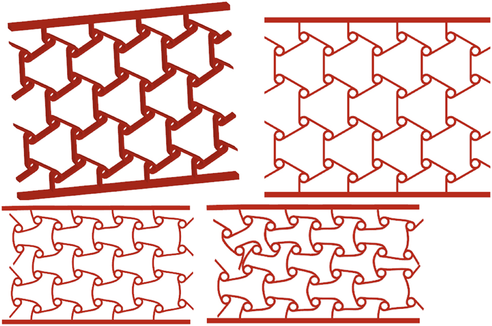
Auxetic materials are specially designed artificial materials with a Negative Poisson’s Ratio (NPR), meaning they have an unusual mechanical response, expanding sideways when stretched and contracting laterally when compressed [5], [6]. These materials are classified based on the structural mechanisms responsible for their auxetic properties. Major categories include reentrant designs [7], [8], [9], [10], arrow-head [11], chiral configurations [12], [13], [14], star shapes [15], antitrichiral [16], meta-chiral (antichiral–reentrant) [17], trichiral [18], meta-chiral [19], and crumpled geometries [20], [22]. Recently, auxetic metamaterials have been used in various fields, such as biomedical applications [23], [24], [25], energy harvesting systems [26], [27], [28], [29], and impact energy absorption [30], [31], [32].
Novel auxetic structures’ innovative design and efficiency were investigated [33]. The performance of a honeycomb, auxetic strut structures, and a hybrid structure is compared. The influence of auxetic structures on crash performance was examined [34]. Utilizing a systematic design approach, they developed three distinct auxetic structures with the dimensions illustrated in the figure. These structures were manufactured via additive manufacturing using SUS316L metal powder. Various structures were designed incorporating negative Poisson’s ratio helical forms, lattice configurations, and high-strength composite materials [35]. Their findings indicated that composites reinforced with auxetic lattice structures exhibited superior mechanical properties. It developed auxetic structures using an innovative design approach and negative Poisson’s ratio properties to create auxiliary structures with unique attributes [36]. The design parameters for these three distinct structures are presented in the accompanying table. A new auxetic structure is proposed [37]. This evaluation was conducted by physically testing 3D-printed samples produced via the selective laser melting (SLM) method and computer simulations. These auxetic structures, manufactured using additive techniques, were designed with predefined dimensions. Conducted research by designing a reentrant model and a hexagonal structure using two types of auxetic materials [38]. They created the models utilizing nylon, carbon-reinforced nylon, and glass-reinforced nylon. The samples required for testing were fabricated through additive manufacturing. Four different auxetic structures were investigated to enhance their energy absorption capabilities [39]. The specific unit cells used in their study are illustrated in Figure 26. They introduced x and y parameters to optimize the energy absorption capacity. It was studied foam-filled structures [40]. They proposed a structure incorporating a double arrow auxetic design, as depicted in the figure, and investigated its energy absorption characteristics. A gradient configuration was established to enhance energy absorption performance, and its effects on energy dissipation were examined. It was designed as an auxetic structure [41].
3 Quasi-static compression analysis of the auxetic structures
This research investigated the crash performance of nine different auxetic structures: reentrant, chiral, antichiral, arrowhead, star, meta-chiral, and a new hybrid auxetic design. As shown in Figure 1, dimensions of the plates are 200 × 160 × 15 mm. Table 1 shows a list of the auxetic structures used in this paper.
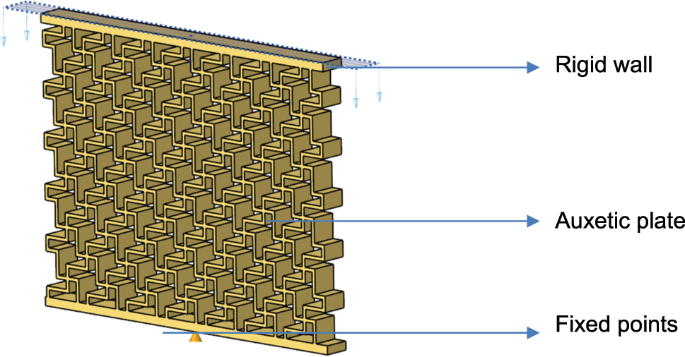
Boundary conditions for the finite element method analysis.
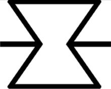
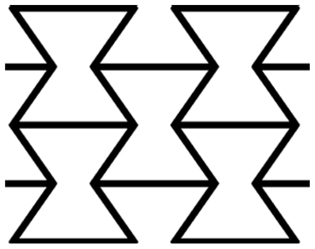
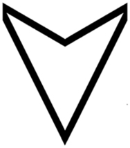
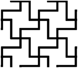
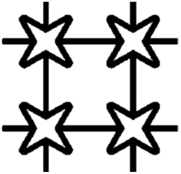
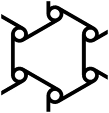
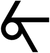
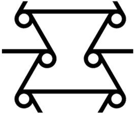
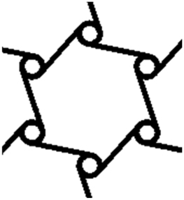
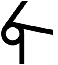
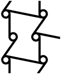
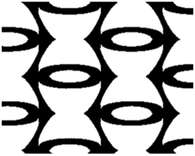
List of auxetic structures used in this paper.
| Types of auxetics | Cellular geometries | Auxetic structures |
|---|---|---|
| Re-entrant [7] |
|
|
| Arrow-head [11] |
|

|
| Chiral [12] |

|
|
| Star [15] |

|
|
| Anti-trichiral [16] |

|
|
| Meta-chiral (Antichiral-reentrant) [17] |
|
|
| Trichiral [18] |

|
|
| Trichiral [19] |
|
|
| Hybrid |

|
|
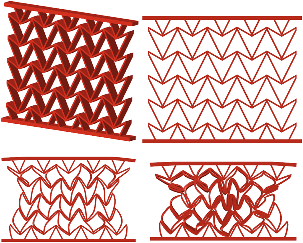
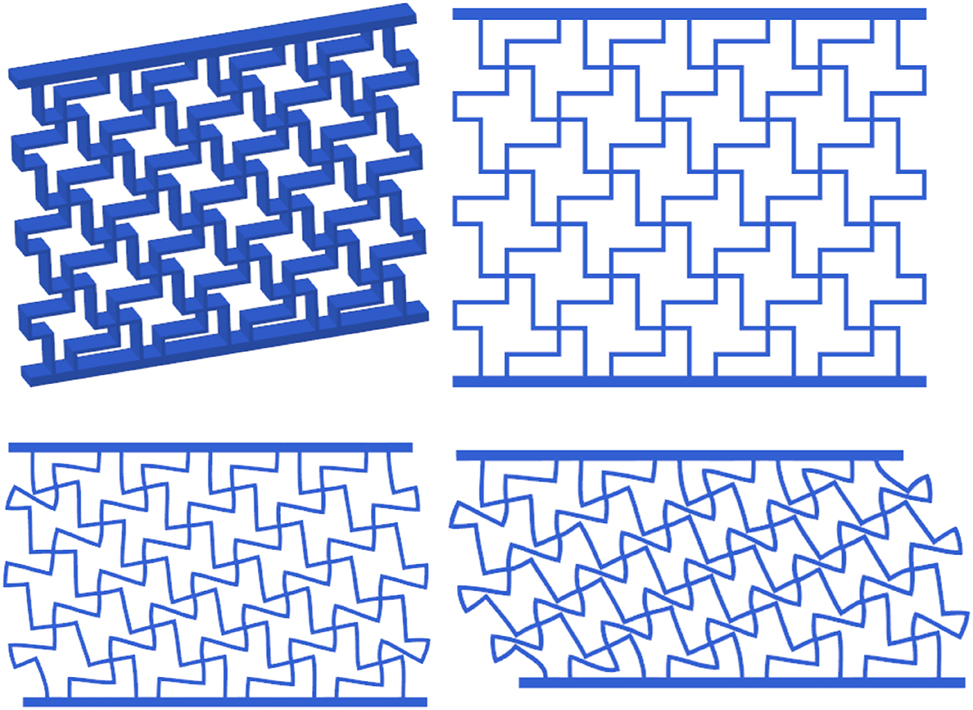
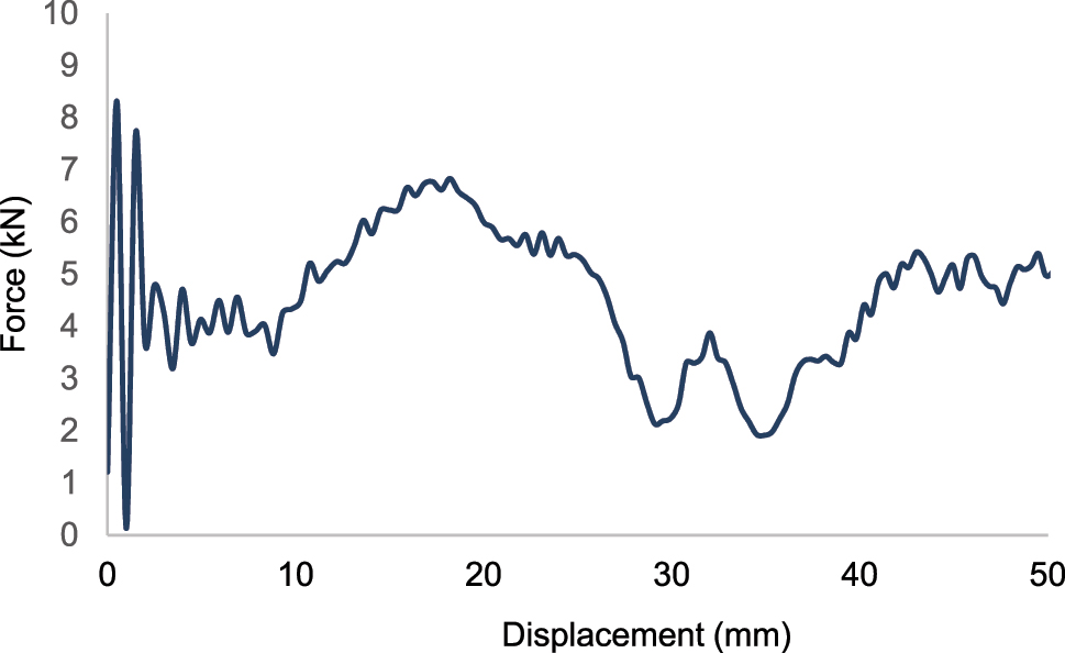
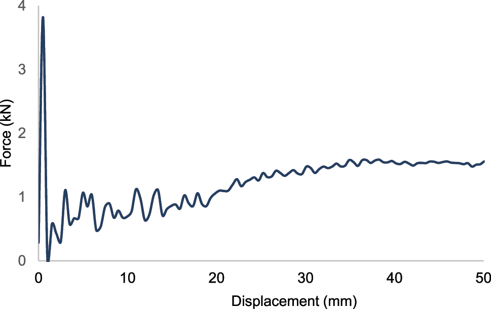
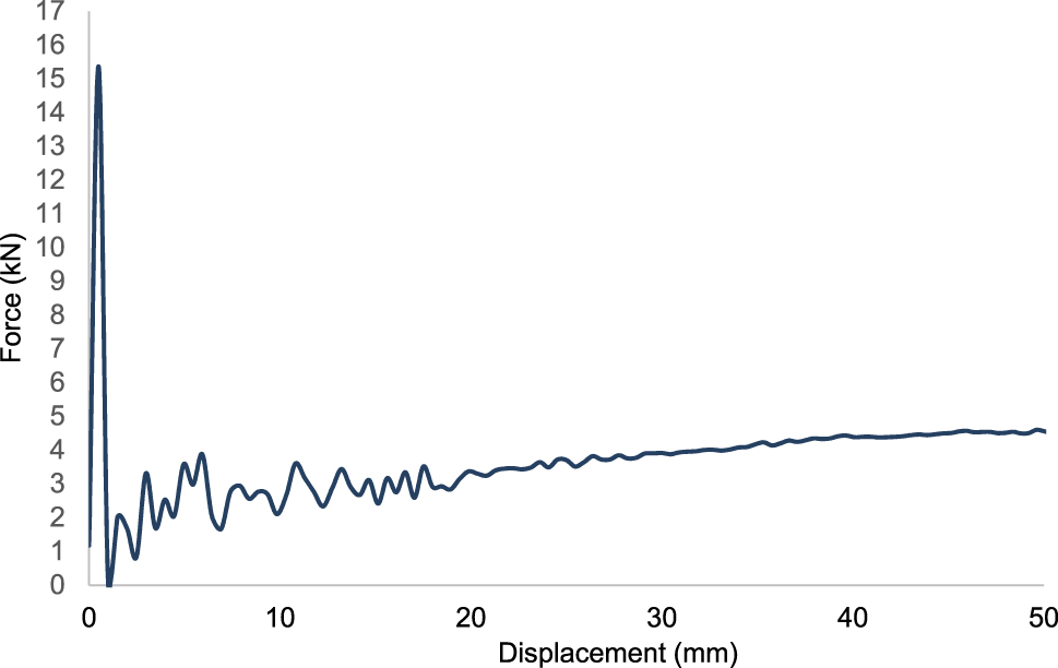
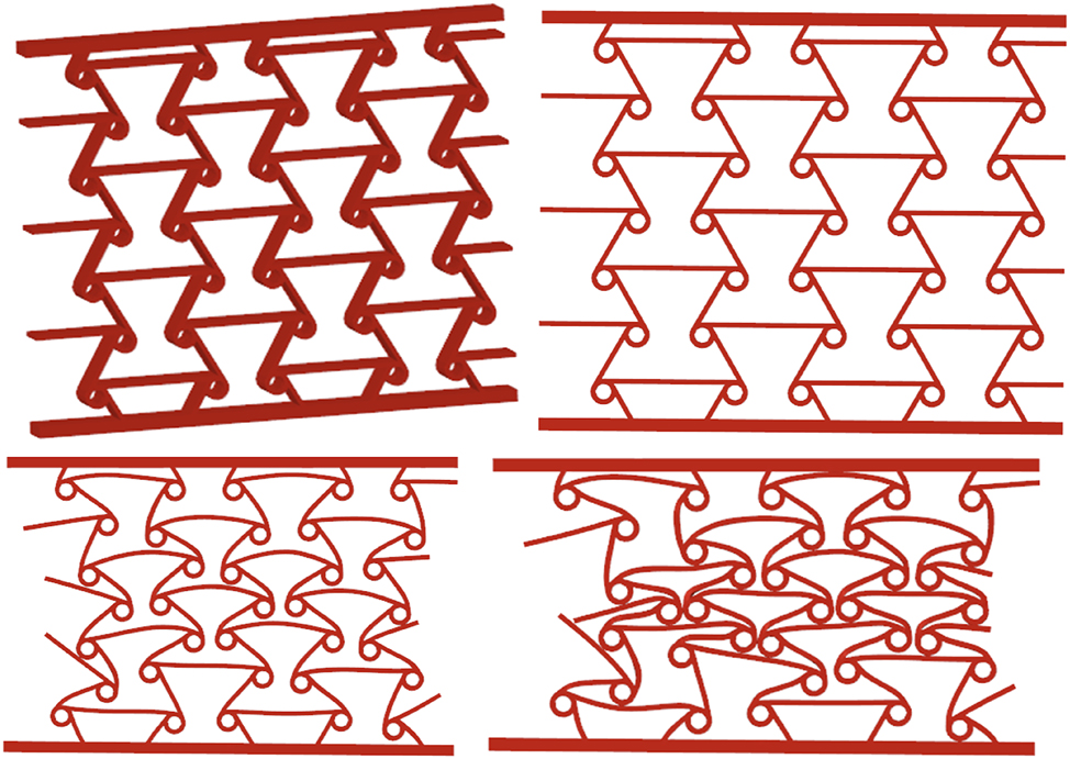
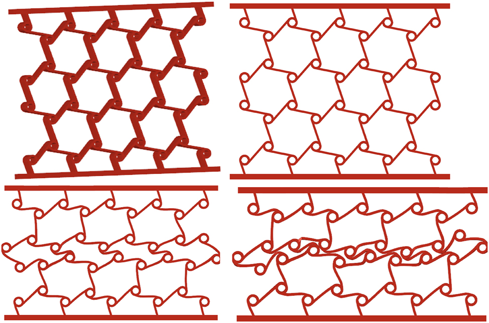
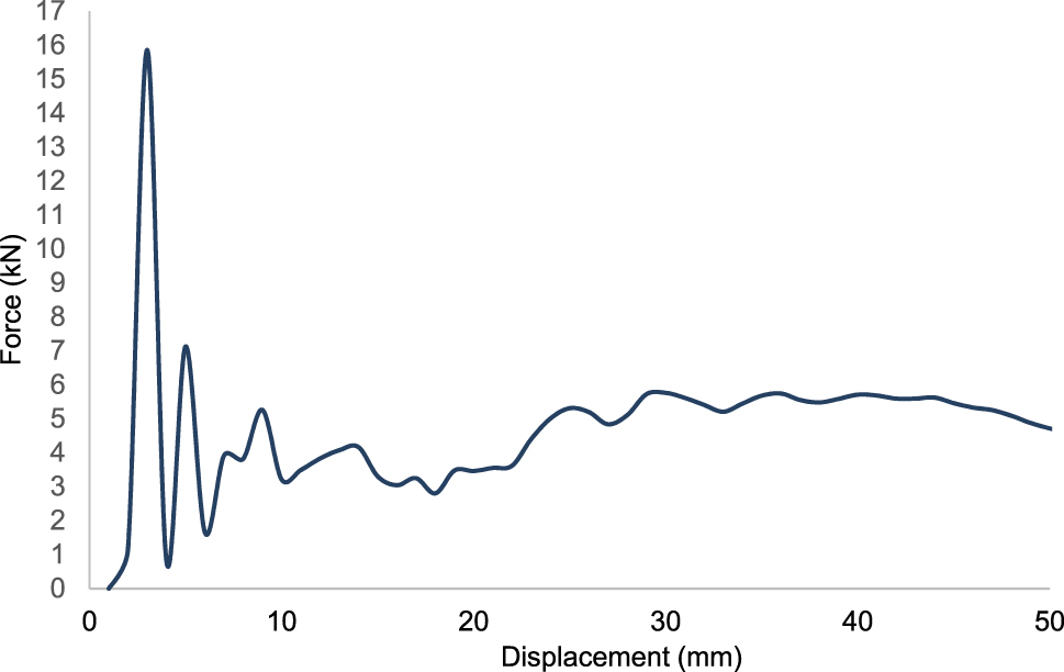
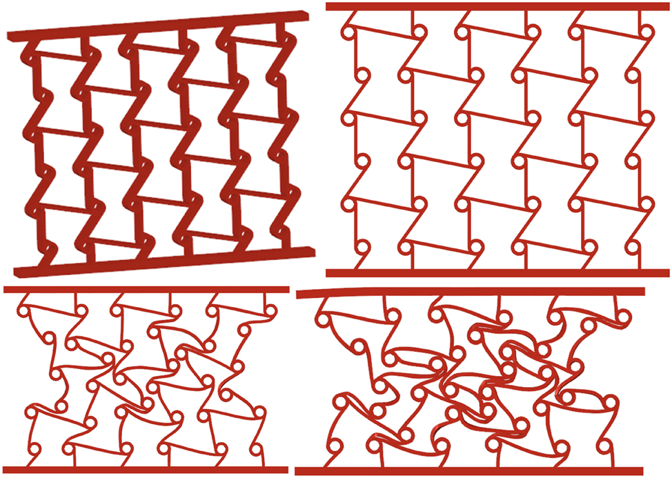
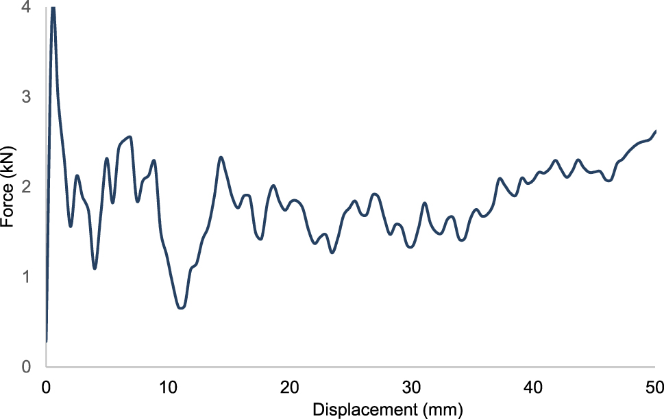
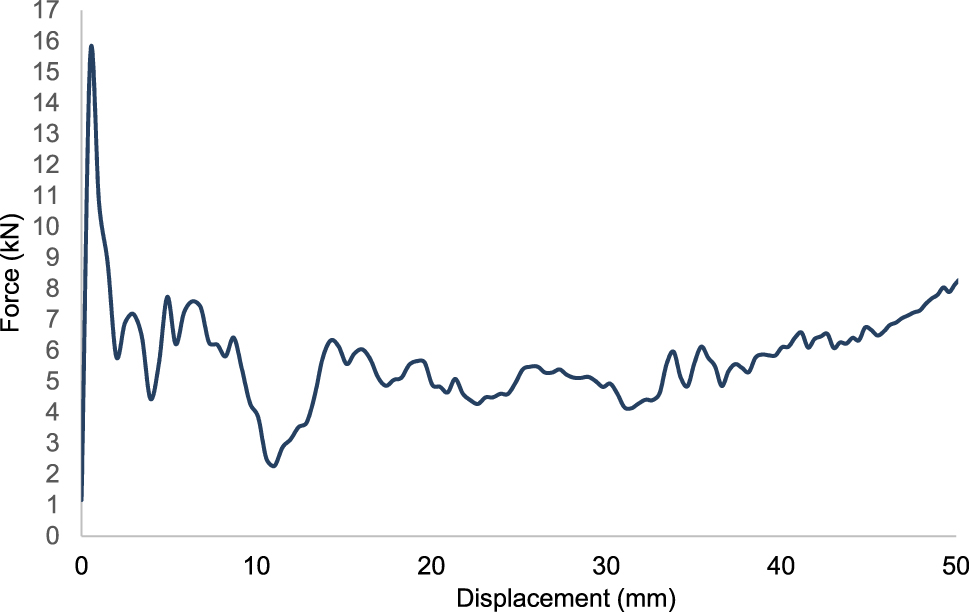
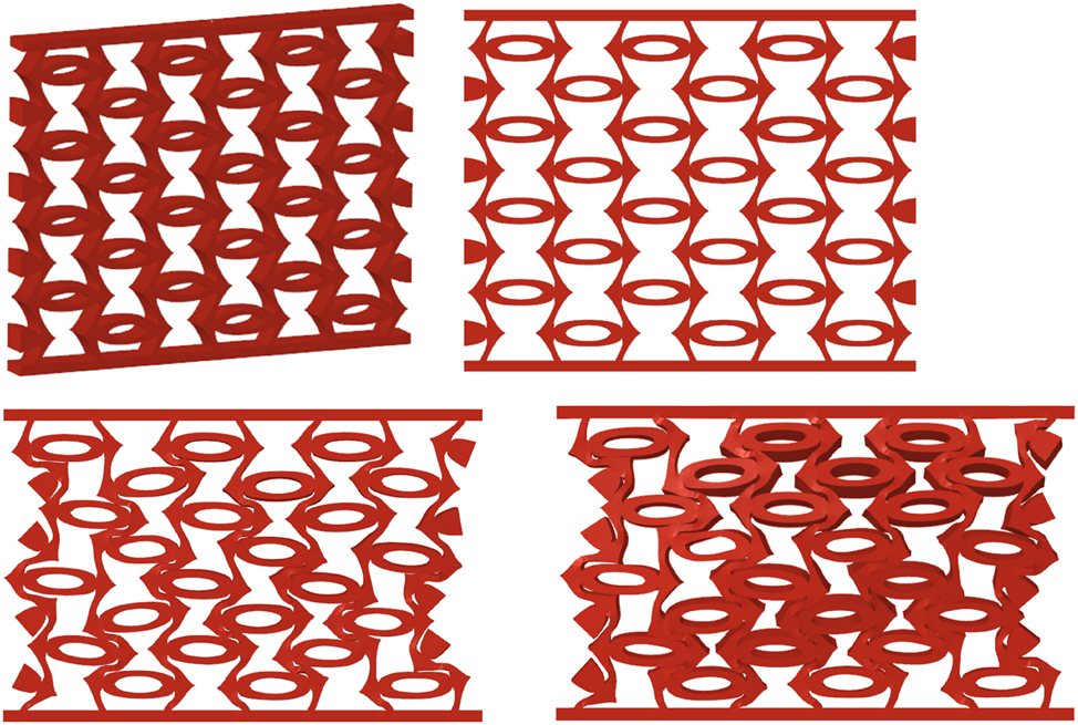
In this research, nine different auxetic plates are designed, as shown in Figures 2, 6, 10, 14, 18, 22, 26, 30, 34. In the same figures, the deformation behaviours of the auxetic structures are also shown. All design crash analyses are completed in Hypermesh RADIOSS under the boundary conditions in Figure 1. The results presented in Table 2, Table 3, and Table 4 for GF30PP, PA6/GF30, and CF15 materials are obtained. The force–displacement curves found from the FEA for the auxetic plates for three different materials, which are GF30pp, Pa 6 GF30, and CF15, are shown in Figures 3, 5, 7, 9, 11, 13, 15,17, and 19, respectively. The mass of the auxetic designs changes from 105.8 to 232.6 g. The specific energy absorption of Design 9 is 2.0922 kJ kg−1, which is better than the rest of the designs for GF30PP material. Design 8 has the best specific energy absorption with 2.2915 kJ kg−1. Design 9 has the best value of specific energy absorption and amount of energy absorption, but the maximum force is the worst of Design 9 for GF30PP material. Design 9 absorbs maximum energy for PA6/GF30 and CF15 materials. However, the peak force of Design 9 for PA6/GF30 and CF15 materials is the biggest.
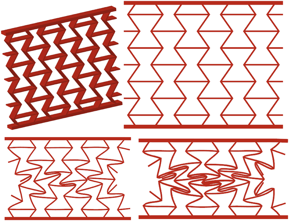
Deformation behavior of design 1 (re-entrant) for GF30PP.
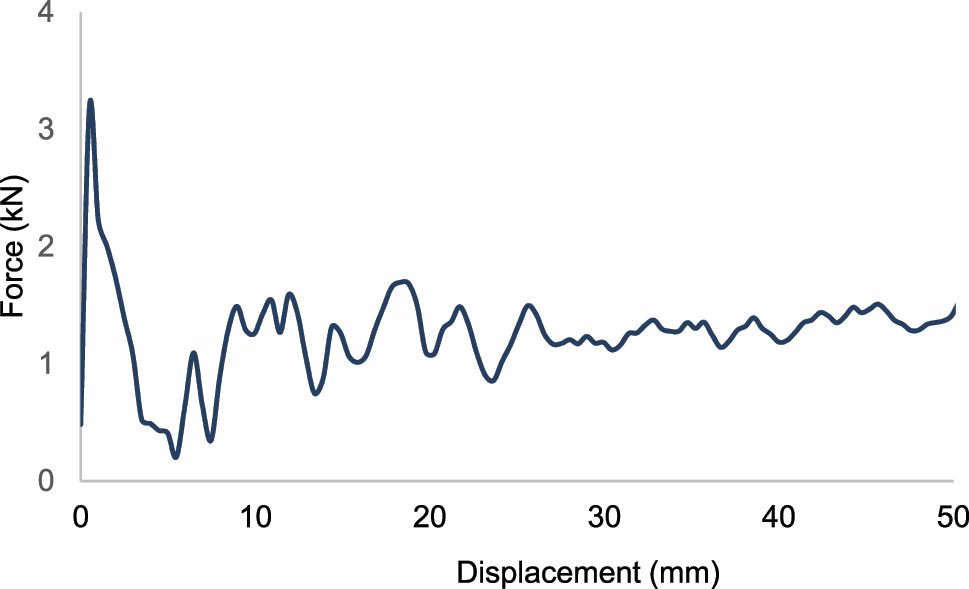
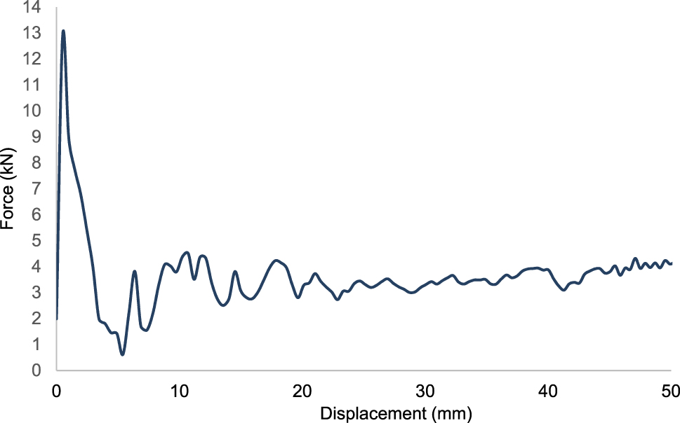
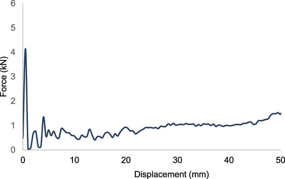
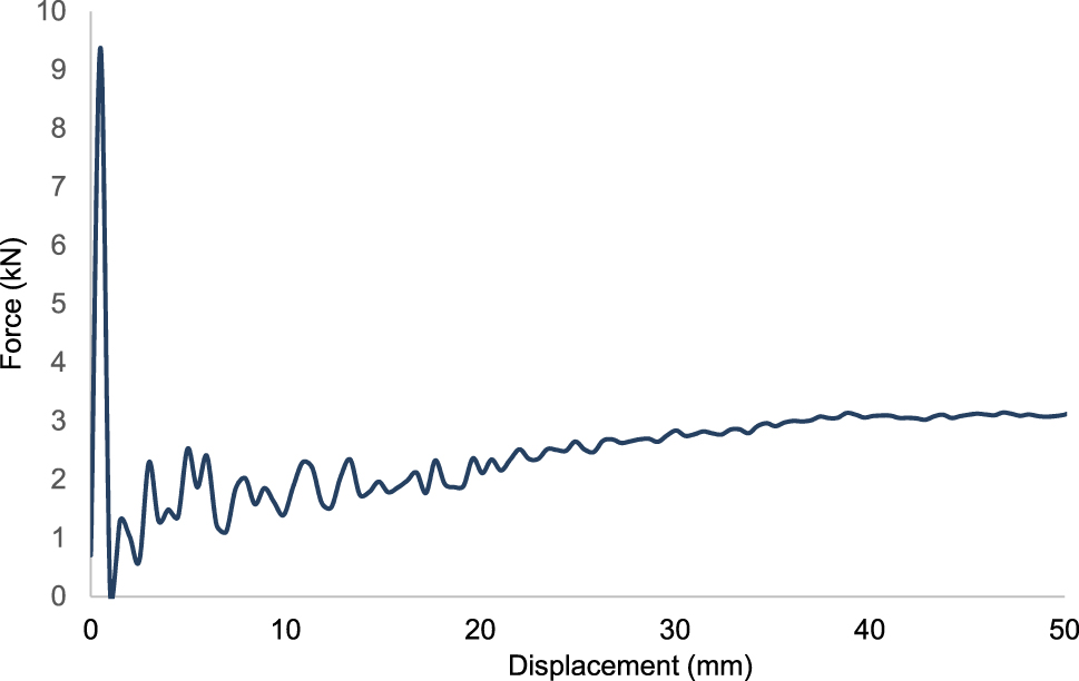
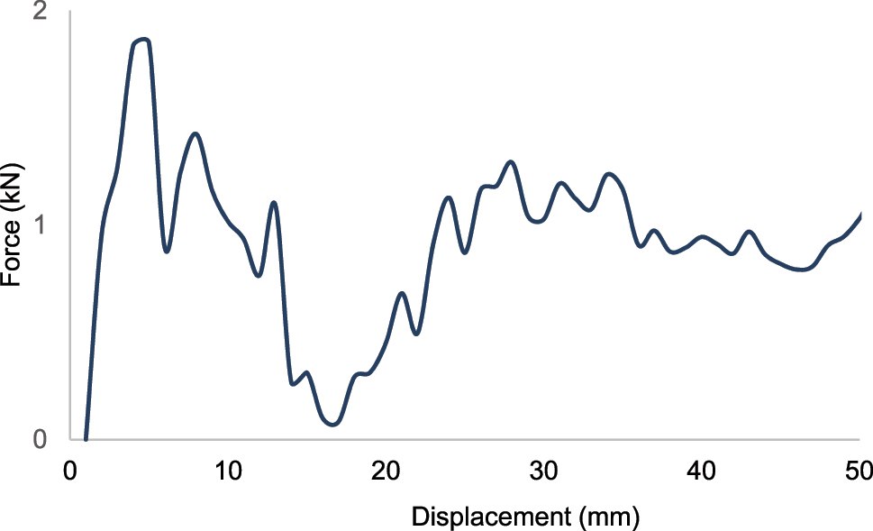
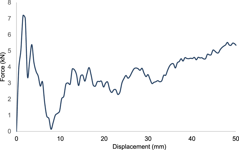
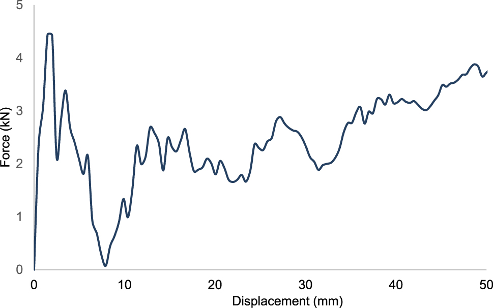
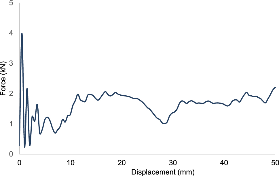
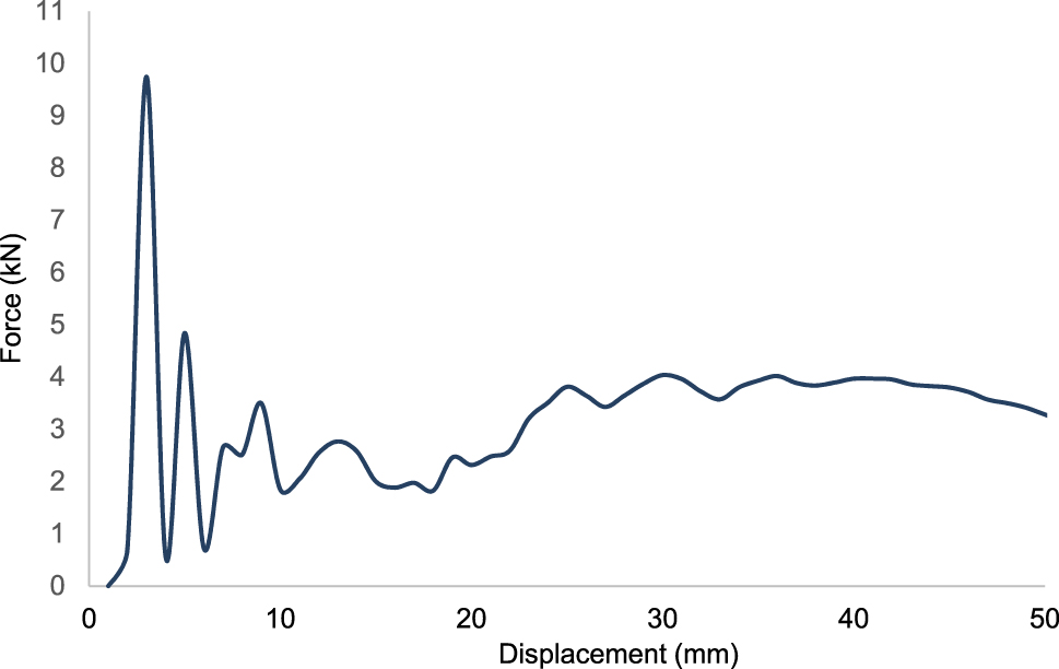
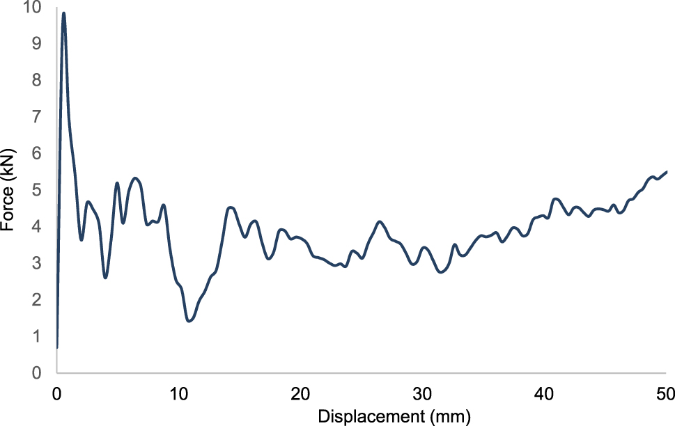
Force-displacement curve for design 1 for 30 % short glass fiber reinforced polypropylene-GF30PP.
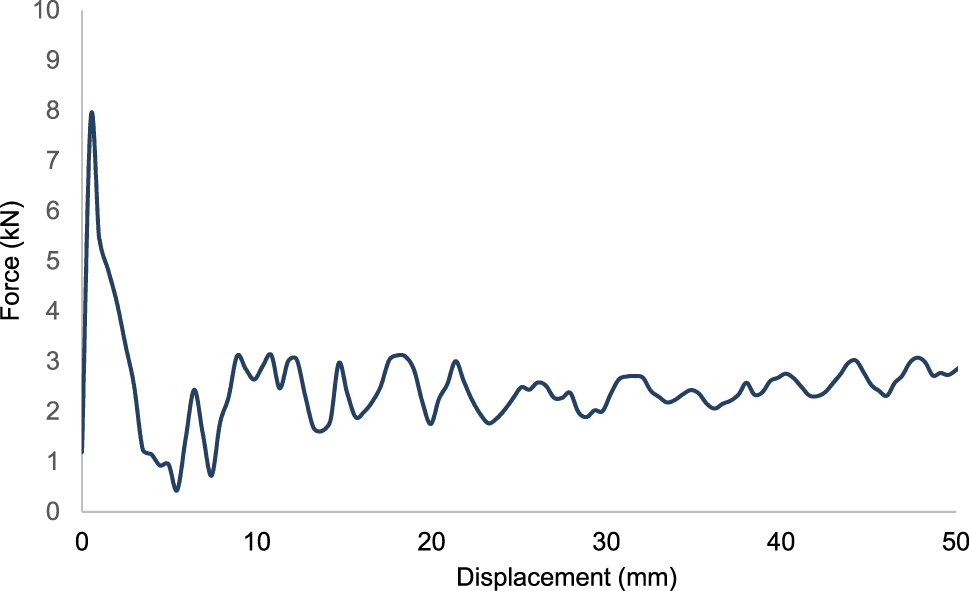
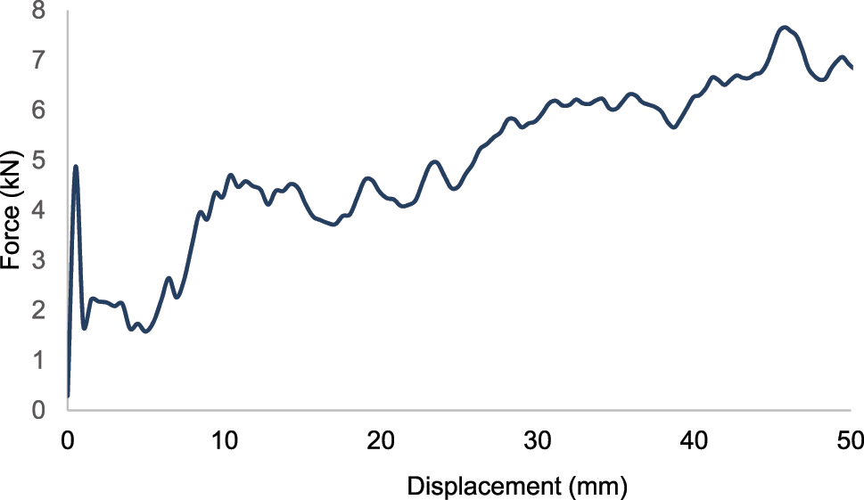
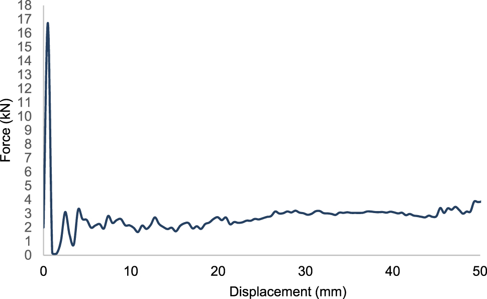
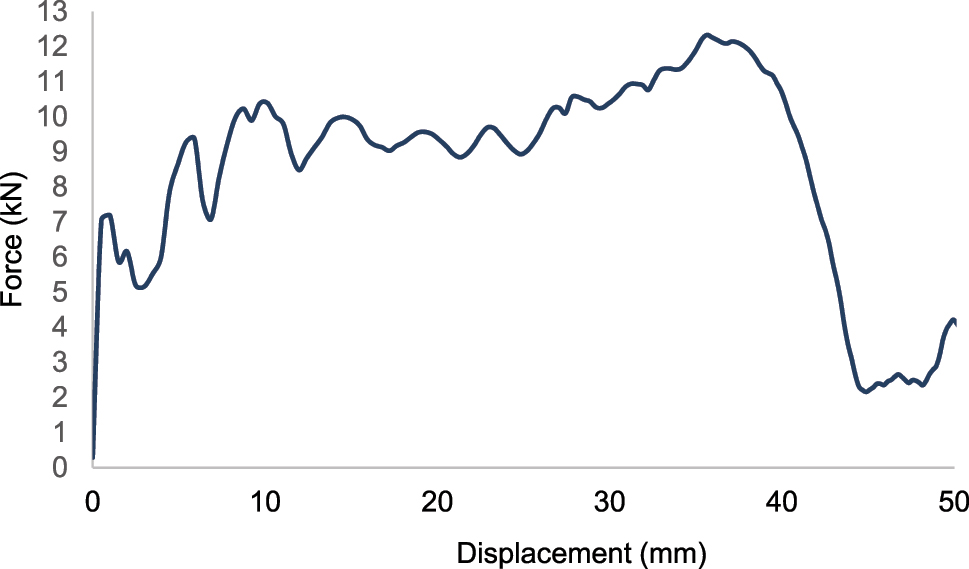
Force-displacement curve for design 1 for polyamide 6 reinforced with 30 % of short glass fiber-PA6 GF30.
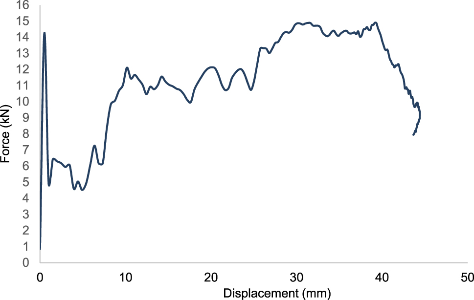
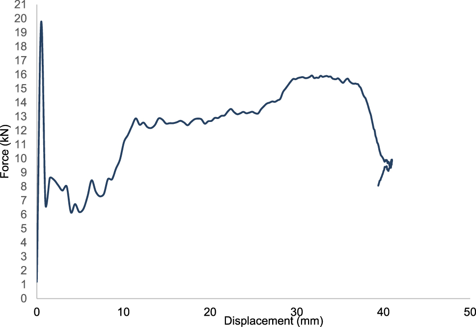
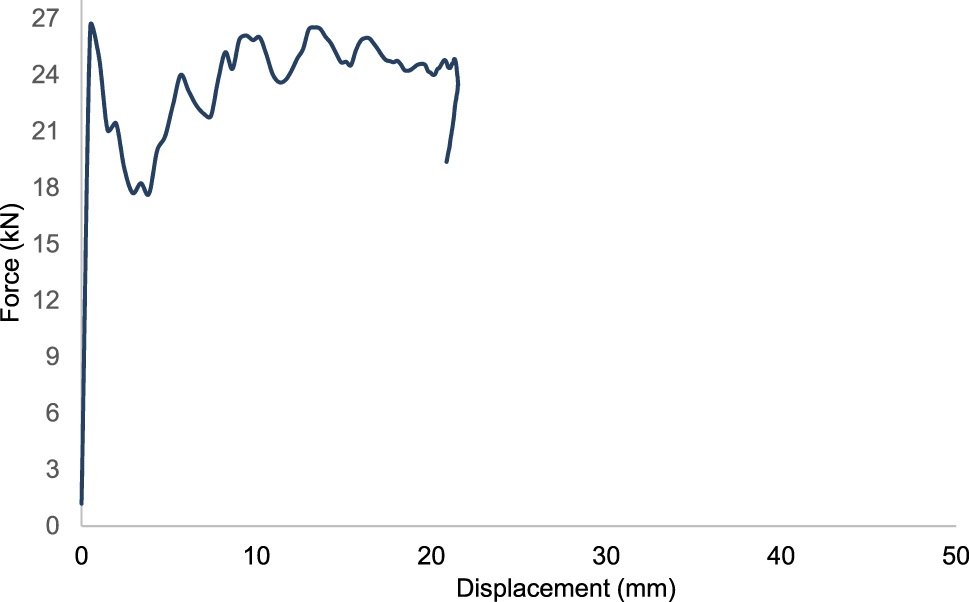
Force-displacement curve for design 1 for high-temperature resistant polyamide with 15 % carbon fiber-CF15.
Deformation behavior of design 2(arrow-head) for 30 % short glass fiber reinforced polypropylene for GF30PP.
Force-displacement curve for design 2 for 30 % short glass fiber reinforced polypropylene-GF30PP.
Force-displacement curve for design 2 for polyamide 6 reinforced with 30 % of short glass fiber-PA6 GF30.
Force-displacement curve for design 2 for high-temperature resistant polyamide with 15 % carbon fiber-CF15.
Deformation behavior of design 3(chiral) for GF30.
Force-displacement curve for design 3 for 30 % short glass fiber reinforced polypropylene-GF30PP.
Force-displacement curve for design 3 for polyamide 6 reinforced with 30 % of short glass fiber-PA6 GF30.
Force-displacement curve for design 2 for high-temperature resistant polyamide with 15 % carbon fiber-CF15.
Deformation behavior of design 4(star) for GF30PP.
Force-displacement curve for design 4 for 30 % short glass fiber reinforced polypropylene-GF30PP.
Force-displacement curve for design 4 for polyamide 6 reinforced with 30 % of short glass fiber-PA6 GF30.
Force-displacement curve for design 2 for high-temperature resistant polyamide with 15 % carbon fiber-CF15.
Deformation behavior of design 5 (anti-chiral) for GF30PP.
Force-displacement curve of design 5 for 30 % short glass fiber reinforced polypropylene for GF30PP.
Force-displacement curve of design 5 for polyamide 6 reinforced with 30 % of short glass fiber-PA6 GF30.
Force-displacement curve for design 2 for high-temperature resistant polyamide with 15 % carbon fiber-CF15.
Deformation behavior of design 6 for GF30 PP.
Force-displacement curve of design 6 for 30 % short glass fiber reinforced polypropylene.
Force-displacement curve of design 6 for polyamide 6 reinforced with 30 % of short glass fiber-PA6 GF30.
Force-displacement curve for design 2 for high-temperature resistant polyamide with 15 % carbon fiber-CF15.
Deformation behavior of design 7(meta-chiral) for GF30PP.
Force-displacement curve of design 7 for 30 % short glass fiber reinforced polypropylene-GF30PP.
Force-displacement curve of design 7 for polyamide 6 reinforced with 30 % of short glass fiber-PA6 GF30.
Force-displacement curve for design 2 for high-temperature resistant polyamide with 15 % carbon fiber-CF15.
Deformation behavior of design 8 for GF30PP.
Force-displacement curve of design 8 for 30 % short glass fiber reinforced polypropylene-GF30PP.
Force-displacement curve of design 8 for polyamide 6 reinforced with 30 % of short glass fiber-PA6 GF30.
Force-displacement curve for design 2 for high-temperature resistant polyamide with 15 % carbon fiber-CF15.
Deformation behavior of design 9 for GF30PP.
Force-displacement curve of design 9 for 30 % short glass fiber reinforced polypropylene-GF30PP.
Force-displacement curve of design 9 for polyamide 6 reinforced with 30 % of short glass fiber-PA6 GF30.
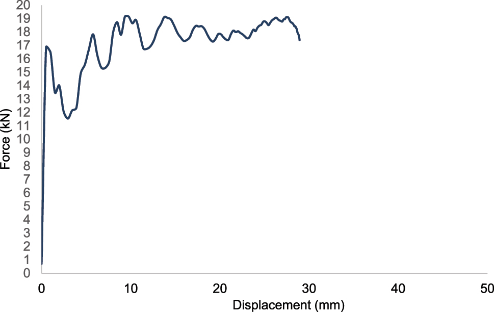
Force-displacement curve for design 2 for polyamide 6 reinforced with 30 % of short glass fiber-CF15.
Comparison of crash performances of the auxetic designs for 30 % short glass fiber reinforced polypropylene-GF30PP.
| Design 1 (re-entrant) | Design 2 (arrow-head) | Design 3 (missing rib) | Design 4 (star) | Design 5 (anti-chiral) | Design 6 (anti-chiral-2) | Design 7 (meta chiral) | Design 8 (meta chiral) | Design 9 (hybrid) | |
|---|---|---|---|---|---|---|---|---|---|
| Mass(gram) | 122.4 | 154.0 | 134.2 | 147.9 | 112.1 | 127.0 | 105.8 | 117.7 | 232.6 |
| Maximum force (kN) | 3.199 | 4.866 | 4.141 | 3.791 | 3.821 | 1.848 | 3.398 | 3.94 | 7.73 |
| Energy absorption (Joule) | 66.8 | 236.1 | 50.4 | 115.9 | 65.1 | 65 | 57.8 | 97.6 | 48.67 |
| Specific energy absorption (kJ/kg) | 0.546 | 1.532 | 0.375 | 0.783 | 0.581 | 0.512 | 0.546 | 0.829 | 2.092 |
Comparison of crash performances of the auxetic designs for polyamide 6 reinforced with 30 % of short glass fiber-Pa6 GF30.
| Design 1 (re-entrant) | Design 2 (arrow-head) | Design 3 (missing rib) | Design 4 (star) | Design 5 (anti-chiral) | Design 6 (anti-chiral-2) | Design 7 (meta chiral) | Design 8 (meta chiral) | Design 9 (hybrid) | |
|---|---|---|---|---|---|---|---|---|---|
| Mass(gram) | 132.2 | 166.3 | 144.9 | 159.7 | 121.1 | 137.2 | 114.3 | 127.1 | 251.2 |
| Maximum force (kN) | 7.8459 | 14.2432 | 10.1745 | 8.3159 | 9.3755 | 4.4418 | 9.7457 | 9.6229 | 16.8558 |
| Energy absorption (Joule) | 126.2 | 323.2 | 95.1 | 230.4 | 127.6 | 127.8 | 165.6 | 196.8 | 349.2 |
| Specific energy absorption (kJ/kg) | 0.9545 | 1.9434 | 0.6566 | 1.4426 | 1.0536 | 0.9316 | 1.4489 | 1.5482 | 1.390 |
Comparison of crash performances of the auxetic designs for high-temperature resistant polyamide with 15 % carbon fiber-CF15.
| Design 1 (re-entrant) | Design 2 (arrow-head) | Design 3 (missing rib) | Design 4 (star) | Design 5 (anti-chiral) | Design 6 (anti-chiral-2) | Design 7 (meta chiral) | Design 8 (meta chiral) | Design 9 (hybrid) | |
|---|---|---|---|---|---|---|---|---|---|
| Mass(gram) | 122.4 | 154.0 | 144.9 | 159.7 | 121.1 | 137.2 | 114.3 | 127.1 | 251.2 |
| Maximum force (kN) | 12.8852 | 19.7427 | 16.7297 | 13.7054 | 15.3605 | 7.1967 | 15.8593 | 15.5479 | 26.5606 |
| Energy absorption (Joule) | 183.8 | 329.8 | 135.5 | 332.6 | 183.4 | 183.9 | 241.4 | 291.3 | 435.5 |
| Specific energy absorption (kJ/kg-1) | 1.3903 | 1.9831 | 0.9348 | 2.0827 | 1.5145 | 1.3405 | 2.1122 | 2.2915 | 1.7338 |
4 Conclusions
This study presents a detailed comparative evaluation of in-plane plate-type auxetic structures, analyzing their mechanical performance. The study highlights how structural configuration influences energy absorption characteristics by investigating various geometrical designs, including reentrant, chiral, antichiral, meta-chiral, arrowhead, star, and a new hybrid auxetic design, Design 9. The materials of the auxetic structures are 30 % short glass fiber reinforced polypropylene (GF30PP), polyamide 6 reinforced with 30 % of short glass fiber (PA6/GF30), and high-temperature resistant polyamide with 15 % carbon fiber (CF15). Findings indicate that Design 9, which is developed in this paper, exhibits the best energy absorption capacity for PA6/GF30 and CF15 materials. Design 8 has the best specific energy absorption with 2.2915 kJ kg−1 for CF15. With advancements in computational simulations, additive manufacturing, and material innovation, auxetic structures can be further optimized for enhanced functionality in lightweight, high-strength, and energy-efficient designs. This research lays the groundwork for future studies exploring hybrid auxetic materials, dynamic loading effects, and large-scale experimental validation, helping bridge the gap between theoretical modeling and real-world engineering applications.
Funding source: Bursa Uludağ University Scientific Research Projects (BAP)
Award Identifier / Grant number: FGA-2023-1316
About the author
Dr. Ali Riza Yildiz is a Professor in the Department of Mechanical Engineering at Bursa Uludağ University, Bursa, Turkey. He is head of the mechanical engineering department and a Full Member of the Turkish Academy of Sciences(TUBA). His research interests are the finite element analysis of structural components, auxetic structures, additive manufacturing, lightweight design, vehicle design, vehicle crashworthiness, shape and topology optimization of vehicle components, and meta-heuristic optimization techniques.
Acknowledgment
This research is supported by the Bursa Uludağ University Scientific Research Projects (BAP) unit under the Research Universities Support Program (ADEP) (Project number: FGA-2023-1316).
-
Research ethics: Not applicable.
-
Informed consent: Not applicable.
-
Author contributions: The author has accepted responsibility for the entire content of this manuscript and approved its submission.
-
Use of Large Language Models, AI and Machine Learning Tools: None declared.
-
Conflict of interest: The author states no conflict of interest.
-
Research funding: None declared.
-
Data availability: Not applicable.
References
[1] C. Zhang and F. Z. Yaoyao, “A critical review on the application of machine learning in supporting auxetic metamaterial design,” J. Phys.: Mater., vol. 7, 2024, https://doi.org/10.1088/2515-7639/ad33a4.Search in Google Scholar
[2] W. Wu, W. Hu, G. Qian, H. Liao, X. Xu, and F. Berto, “Mechanical design and multifunctional applications of chiral mechanical metamaterials: a review,” Mater. Des., vol. 180, p. 107950, 2019, https://doi.org/10.1016/j.matdes.2019.107950.Search in Google Scholar
[3] K. Bertoldi, P. M. Reis, S. Willshaw, and T. Mullin, “Negative Poisson’s ratio behavior induced by an elastic instability,” Adv. Mater., vol. 22, no. 3, pp. 361–366, 2010, https://doi.org/10.1002/adma.200901956.Search in Google Scholar
[4] L. Yang, O. Harrysson, H. West, and D. Cormier, “Mechanical properties of 3D re-entrant honeycomb auxetic structures realized via additive manufacturing,” Int. J. Solids Struct., vol. 69, no. 70, pp. 475–490, 2015, https://doi.org/10.1016/j.ijsolstr.2015.05.005.Search in Google Scholar
[5] K. E. Evans and A. Alderson, “Auxetic materials: functional materials and structures from lateral thinking,” Adv. Mater., vol. 12, no. 9, pp. 617–628, 2000, https://doi.org/10.1002/(SICI)1521-4095(200005)12:9<617::AID-ADMA617>3.0.CO;2-3.10.1002/(SICI)1521-4095(200005)12:9<617::AID-ADMA617>3.0.CO;2-3Search in Google Scholar
[6] K. E. Evans and K. Alderson, “Auxetic materials: the positive side of being negative,” Eng. Sci. Educ. J., vol. 9, no. 4, pp. 148–154, 2000, https://doi.org/10.1049/esej:20000402.10.1049/esej:20000402Search in Google Scholar
[7] F. Robert, “An isotropic three-dimensional structure with Poisson’s ratio = −1,” J. Elast, vol. 15, no. 4, pp. 427–430, 1985, https://doi.org/10.1007/BF00042531.Search in Google Scholar
[8] X. -T. Wang, B. Wang, X. -W. Li, and L. Ma, “Mechanical properties of 3D re-entrant auxetic cellular structures,” Int. J. Mech. Sci., vol. 131, pp. 396–407, 2017, https://doi.org/10.1016/j.ijmecsci.2017.05.048.Search in Google Scholar
[9] A. Alomarah, D. Ruan, and S. Masood, “Tensile properties of an auxetic structure with re-entrant and chiral features–a finite element study,” Int. J. Adv. Manuf. Technol., vol. 99, nos. 9–12, pp. 2425–2440, 2018, https://doi.org/10.1007/s00170-018-2637-y.Search in Google Scholar
[10] V. Lvov, F. S. Senatov, A. M. Korsunsky, and A. I. Salimon, “Design and mechanical properties of 3D-printed auxetic honeycomb structure,” Mater. Today Commun., 2020, https://doi.org/10.1016/j.mtcomm.2020.101173.Search in Google Scholar
[11] U. D. Larsen, O. Signund, and S. Bouwsta, “Design and fabrication of compliant micromechanisms and structures with negative Poisson’s ratio,” J. Microelectromech. Syst., vol. 6, no. 2, pp. 99–106, 1997, https://doi.org/10.1109/84.585787.Search in Google Scholar
[12] D. Prall and S. R. Lakes, “Properties of a chiral honeycomb with a Poisson’s ratio of-1,” Int. J. Mech. Sci., vol. 39, no. 3, pp. 305–314, 1997, https://doi.org/10.1016/S0020-7403(96)00025-2.Search in Google Scholar
[13] S. Ghaedizadeh, R. Mirzaeifar, A. M. Masoudi, and J. B. Gibson, “A review on auxetic structures,” J. Mater. Res. Technol., vol. 9, no. 5, pp. 12205–12230, 2020, https://doi.org/10.1016/j.jmrt.2020.08.057.Search in Google Scholar
[14] G. Imbalzano, T. Ngo, P. Tran, and P. Vrcelj, “Design and mechanical properties of additively manufactured auxetic polymeric metamaterials,” Mater. Des., vol. 160, pp. 1200–1212, 2018, https://doi.org/10.1016/j.matdes.2018.11.008.Search in Google Scholar
[15] J. N. Grima, R. Gatt, A. Alderson, and K. E. Evans, “On the potential of connected stars as auxetic systems,” Mol. Simul., vol. 31, no. 13, pp. 925–935, 2005, https://doi.org/10.1080/08927020500401139.Search in Google Scholar
[16] A. Alderson, et al.., “Elastic constants of 3-4-and 6-connected chiral and anti-chiral honeycombs subject to uniaxial in-plane loading,” Compos. Sci. Technol., vol. 70, no. 7, pp. 1042–1048, 2010, https://doi.org/10.1016/j.compscitech.2009.07.009.Search in Google Scholar
[17] X. L. Ruan, et al.., “Mechanical design of antichiral-reentrant hybrid intravascular stent,” Int. J. Appl. Mech., vol. 10, no. 10, 2018, https://doi.org/10.1142/S1758825118501053.Search in Google Scholar
[18] A. Bacigalupo and ML De Bellis, “Auxetic anti-tetrachiral materials: equivalent elastic properties and frequency band-gaps,” Compos. Struct., vol. 131, pp. 530–544, 2015, https://doi.org/10.1016/j.compstruct.2015.05.039.Search in Google Scholar
[19] W. Wu, W. Hu, G. Qian, H. Liao, X. Xu, and F. Berto, “Mechanical design and multifunctional applications of chiral mechanical metamaterials: a review,” Mater. Des., vol. 180, 2019, https://doi.org/10.1016/j.matdes.2019.107950.Search in Google Scholar
[20] M. Ruzzene, P. M. Reis, and M. Gei, “Auxetic materials: mechanical metamaterials exhibiting negative Poisson’s ratio,” J. Appl. Mech., vol. 85, no. 11, 2018, https://doi.org/10.1115/1.4041656.Search in Google Scholar
[21] J. Li, Z. Wang, and Y. Shen, “3D printing of auxetic metamaterials for biomedical applications,” Mater. Today, vol. 32, pp. 85–95, 2020, https://doi.org/10.1016/j.mattod.2020.08.001.Search in Google Scholar
[22] T. A. Schaedler and W. B. Carter, “Architected cellular materials,” Annu. Rev. Mater. Res., vol. 46, pp. 187–210, 2016, https://doi.org/10.1146/annurev-matsci-070115-032036.Search in Google Scholar
[23] X. Ren, R. Das, P. Tran, T. D. Ngo, and Y. M. Xie, “Auxetic metamaterials and structures: a review,” Smart Mater. Struct., vol. 27, no. 2, 2018, https://doi.org/10.1088/1361-665X/aaa61c.Search in Google Scholar
[24] M. Kadic, T. Bückmann, R. Schittny, and M. Wegener, “Metamaterials beyond electromagnetism,” Rep. Prog. Phys., vol. 76, no. 12, 2013, https://doi.org/10.1088/0034-4885/76/12/126501.Search in Google Scholar PubMed
[25] Z. Wei, Y. Gu, and J. Zhu, “Programmable auxetic mechanical metamaterials,” Mater. Des., vol. 160, pp. 557–568, 2018, https://doi.org/10.1016/j.matdes.2018.09.041.Search in Google Scholar
[26] R. Lakes, “Foam structures with a negative Poisson’s ratio,” Science, vol. 235, no. 4792, pp. 1038–1040, 1987, https://doi.org/10.1126/science.235.4792.1038.Search in Google Scholar PubMed
[27] C. Coulais, C. Kettenis, and M. van Hecke, “A characteristic length scale causes anomalous size effects and boundary programmability in mechanical metamaterials,” Nat. Phys., vol. 14, pp. 40–44, 2018, https://doi.org/10.1038/nphys4269.Search in Google Scholar
[28] S. Shan, et al.., “Multistable architected materials for trapping elastic strain energy,” Adv. Mater., vol. 27, no. 29, pp. 4296–4301, 2015, https://doi.org/10.1002/adma.201501708.Search in Google Scholar PubMed
[29] G. Zhang, P. Cao, Y. Zhang, and X. Jin, “Energy absorption of 3D-printed re-entrant honeycomb structures under dynamic loading,” Int. J. Mech. Sci., pp. 161–162, 2019, https://doi.org/10.1016/j.ijmecsci.2019.105064.Search in Google Scholar
[30] X. Ren, P. Tran, T. D. Ngo, and Y. M. Xie, “Bi-material auxetic mechanical metamaterials with tunable mechanical properties,” Adv. Mater., vol. 32, no. 3, 2019, https://doi.org/10.1002/adma.201905233.Search in Google Scholar
[31] M. Shruti, N. S. Hemanth, N. D. Badgayan, and S. K. Sahu, “Compressive behavior of auxetic structural metamaterial for lightweight construction using ANSYS static structural analysis,” Mater. Today: Proc., 2020, https://doi.org/10.1016/j.matpr.2020.05.410.Search in Google Scholar
[32] R. Hamzehei, S. Rezaei, J. Kadkhodapour, A. P. Anaraki, and A. Mahmoudi, “2D triangular anti-trichiral structures and auxetic stents with symmetric shrinkage behavior and high energy absorption,” Mech. Mater., vol. 142, p. 103291, 2020, https://doi.org/10.1016/j.mechmat.2019.103291.Search in Google Scholar
[33] A. Ingrole, A. Hao, and R. Liang, “Design and modeling of auxetic and hybrid honeycomb structures for in-plane property enhancement,” Mater. Des., vol. 117, pp. 72–83, 2017, https://doi.org/10.1016/j.matdes.2016.12.067.Search in Google Scholar
[34] W. Lee, et al.., “Effect of auxetic structures on crash behavior of cylindrical tube,” Compos. Struct., vol. 208, pp. 836–846, 2019, https://doi.org/10.1016/j.compstruct.2018.10.068.Search in Google Scholar
[35] T. Li, Y. Chen, X. Hu, Y. Li, and L. Wang, “Exploiting negative Poisson’s ratio to design 3D-printed composites with enhanced mechanical properties,” Mater. Des., vol. 142, pp. 247–258, 2018, https://doi.org/10.1016/j.matdes.2018.01.034.Search in Google Scholar
[36] H. Najafi, H. Ahmadi, and G. Liaghat, “Experimental investigation on energy absorption of auxetic structures,” Mater. Today: Proc., vol. 34, pp. 350–355, 2019, https://doi.org/10.1016/j.matpr.2020.06.075.Search in Google Scholar
[37] V. A. Lvov, F. S. Senatov, A. M. Korsunsky, and A. I. Salimon, “Design and mechanical properties of 3D-printed auxetic honeycomb structure,” Mater. Today Commun., vol. 24, p. 101173, 2020, https://doi.org/10.1016/j.mtcomm.2020.101173.Search in Google Scholar
[38] K. Günaydın, C. Rea, and Z. Kazancı, “Energy absorption enhancement of additively manufactured hexagonal and re-entrant (auxetic) lattice structures by using multi-material reinforcements,” Addit. Manuf., vol. 59, p. 103076, 2022, https://doi.org/10.1016/j.addma.2022.103076.Search in Google Scholar
[39] S. Bronder, et al.., “Hybrid auxetic structures: structural optimization and mechanical characterization,” Adv. Eng. Mater., vol. 23, no. 5, 2021, https://doi.org/10.1002/adem.202001393.Search in Google Scholar
[40] Q. Gao and W. H. Liao, “Energy absorption of thin-walled tube filled with gradient auxetic structures-theory and simulation,” Int. J. Mech. Sci., vol. 201, p. 106475, 2021, https://doi.org/10.1016/j.ijmecsci.2021.106475.Search in Google Scholar
[41] R. Valle, G. Pincheira, V. Tuninetti, E. Fernandez, and E. Uribe-Lam, “Design and characterization of asymmetric cell structure of auxetic material for predictable directional mechanical response,” Materials, vol. 15, no. 5, 2022, https://doi.org/10.3390/ma15051841.Search in Google Scholar PubMed PubMed Central
© 2025 the author(s), published by De Gruyter, Berlin/Boston
This work is licensed under the Creative Commons Attribution 4.0 International License.
Articles in the same Issue
- Frontmatter
- Effect of flush grinding on corrosion fatigue behavior of step-aged 7020 aluminum alloys
- Bending behavior of corrugated sandwich panels with various core shapes
- Comparison of crash performance of auxetic structures for CF15, PA6/GF30, and GF30PP materials
- Combined effect of ball milling and high-pressure torsion on mechanical properties of Al2O3/Al composite
- Liquid metal embrittlement susceptibility of galvanized advanced high strength steel with high manganese content
- Kinetic study on nickel aluminides formed on Monel 400 alloy
- Finite element simulation of natural gas pipelines in service welding repair
- Biomechanical effects of material selection and micro-groove design for dental implants
- Design, FEA and experimental validation of 3D-printed PLA/PCL intervertebral cages for lumbar spinal fusion
- Effect of tool tilt angles on the formation of YSZ/Al2O3 hybrid surface composites on friction stir processed magnesium alloy AZ31
- Coating of AISI 304 stainless steel surface with addition of Cr3C2 to NiCrCo medium entropy alloy powder
- Numerical and analytical stress analysis for a FGM beam
- Mechanical and wear behaviour of hybrid AA8011 metal matrix composite reinforced with aluminum silicate and titanium dioxide
- A new neural network–assisted hybrid chaotic hiking optimization algorithm for optimal design of engineering components
- Cup drawing predictions for a 6016-T4 aluminum alloy