Biomechanical effects of material selection and micro-groove design for dental implants
-
Efe Savran
Efe Savran, born in 1993. He received B.Sc. from Balikesir University. Currently, he is a PhD candidate in the mechanical engineering department of Bursa Uludag University. As a scholarship holder of The Scientific and Technological Research Council of Turkey (TUBITAK), he is a co-worker of Karsan Automotive. His interest areas are electrified powertrains, energy-efficient driving analysis, biomedical applications, and finite element methods. He has national and international academic publications in his research areas.
Prof. Dr. Fatih Karpat, born in 1977, Professor Dr. at the Mechanical Engineering department at Bursa Uludag University. He received his BSc in 1998, MSc in 2001, and PhD in 2005 from Bursa Uludag University. He joined the academic community as a research assistant in 1998 and he continued his success by gaining the title of associate professor in 2015 and professor in 2020. He has been to Texas Tech University and the University of Central Oklahoma between 2006 and 2015 as a postdoctoral and guest researcher. His professions are based on machine elements, biomedical engineering, sustainability, and MEMS. He has more than 20 science citation-indexed publications, 5 book chapters, and more than 70 academic conference publications. Besides the academic side, he also managed more than 20 industrial projects.


Abstract
In this study, biomechanical evaluation was performed to select appropriate dental implant material, and the implant-bone model was verified by finite element analysis (FEA). Ti–6Al–4V, ZK60, WE43, HA, and Ta materials were compared using three different multi-criteria decision-making (MCDM) methods according to lightness, functional durability, relative movement, penetration, and cost criteria. The stress, deformation, safety factor, sliding distance, and penetration distributions obtained under four loading conditions were scored according to these evaluation criteria and Ti–6Al–4V was determined as the most successful material. By adding 0.1 mm wide and deep micro-grooves to the dental implant model, an 8.3 % improvement in sliding distance and a 53 % improvement in penetration were achieved.
1 Introduction
Dental implants are synthetic roots placed in the jawbone to compensate for the physical deficiency caused by tooth loss. They are used to eliminate chewing inadequacy and improve aesthetic appearance. Implant installation is performed by considering the general health of the patient’s jawbone and the healing process continues. Correct geometry and appropriate material selection are important for implants’ long lives. Titanium alloys [1] and biocompatible ceramics [2] are today’s most commonly used implant materials. However, alternative materials such as magnesium alloys [3] have been investigated regarding their biomechanical performance and bone compatibility. The geometrical features of dental implants affect the life of the implant. Shape, size, surface, and design are critical in biomechanical performance. In the screw-like implant shape, the screw dimensions affect the implant placement and the uniformity of the load on the implant surface [4]. The surface of the implant is effective for osseointegration [5]. A rough implant surface allows bone cells to adhere better to the implant surface. Surface treatments applied to the implant help implant-bone integration.
FEA [6], [7] enables an easy understanding of complex structural behaviors [8], [9], the creation of optimal designs, and the determination of weak points in the structure [10]. FEA, which enables simulating real-world mechanical behavior and saves time and cost, works on the principle of tear down engineering problems into solvable sub-parts [11]. These parts are small, simple, and interconnected subsystems called finite elements. The structure is geometrically divided into small elements and information about the behavior of the entire structure is obtained by establishing and solving appropriate equations between these elements. The most important advantage of this method is that it allows solving situations that are difficult and time-consuming to realize with experimental methods. With the help of FEA, various physical outputs such as stress, deformation, vibration, and fatigue can be easily predicted in response to external forces that a structure is exposed to [12]. FEA is also a critical tool for understanding and optimizing biomechanical performance in dental implants. It allows detailed examination of the contact of complex geometry implants with the jawbone [13]. It provides a detailed examination of the stresses, deformations, and force distributions that occur after implant installation. Thus, predictions can be made for potential problems that may occur under different conditions. New designs can be created with FEA and biomechanical examination of various materials can be made possible. By simulating the mechanical behavior of an implant under multiple loading conditions, the most suitable implant form can be created, and the installation method can be determined. It is also possible to compare the mechanical behavior of different materials such as titanium and magnesium alloys. With FEA, the biocompatibility and long-term success of implants can be easily increased.
Various engineering materials are used in biomedical applications. Among these, titanium alloys and magnesium are among the most important metals and have a wide range of uses due to their different properties. Examining the biocompatibility and biomechanical properties of these materials will ensure that a successful implant is obtained [14]. Titanium stands out with its high biocompatibility, high strength, superior corrosion resistance, and compatibility with additive manufacturing [15]. Thanks to these properties, it is widely preferred in dental implants, hip and knee prostheses, and spinal screws [16]. On the other hand, magnesium is gaining increasing interest, especially in biodegradable implants. Since magnesium can dissolve in contact with body fluids due to its characteristics, it has great potential as a biodegradable implant material [17]. This feature is important in applications such as screws and plates that break down over time during the bone healing process and give way to natural bone. In addition, it creates an effect that increases patient comfort by providing biomechanical compatibility with its elastic modulus close to bone tissue. Hydroxyapatite (HA) is a ceramic similar to bone tissue and improves bone-implant interaction thanks to its osteoinductive and osteoconductive properties [18]. This feature makes HA a preferred material for dental implants [19]. Tantalum (Ta) is a dense and hard metal in its natural state with high biocompatibility, corrosion resistance, and mechanical strength [20]. Tantalum has also made a name for itself in many medical studies thanks to its positive properties.
1.1 Literature survey
Kalay et al. [21] conducted numerical research to see the titanium implant shape effect on bone-implant integration. They modeled four different dental implant grooves and analyzed them under four loading conditions with the help of FEA. They found that the buttressed groove is the appropriate model for the specified implant model. Roatesi and Roatesi [22] examined an accurate Ti6–Al–4VS implant model in bone. Axial and horizontal loadings were applied to the dental implant by using FEA. They have reached out to highlight the weak areas of the dental implant. Lee et al. [23] compared the cement-retained and cementless zirconia crown screws by using FEA. Under two different loading conditions, the cementless screw model showed better mechanical results. Ibrahim et al. [24] investigated the biomechanical behavior of two different Titanium dental implants by using FEA. Dhatrak et al. [25] compared isotropic and orthotropic material models on the four different dental implant models. They observed the mechanical responses of different materials under the same boundary conditions by using FEA. According to their results, orthotropic material is superior given comparison. Paracchini et al. [26] compared two different groove types on Titanium dental implants. Two different loading conditions were evaluated in the FEA setup. Roatesi and Roatesi [27] aimed to evaluate the success of the implant osseointegration with a finite element model. They simulated the osseointegration process by FEA. In this reference, Magnesium alloy was used in the intermediate, Titan alloy in the implant and screw, and Ceramic was used in the crown of the dental implant. Choi and Hong [28] used FEA in their study to determine the optimal tightening torque for two-piece zirconia implants. The stress values formed by three different tightening torque trials were examined. It was observed that the determined optimal tightening torque was sufficient for the stability of the implant system and had no effect on the trabecular and cortical bone regions. In the study conducted by Wang et al. [29], finite element model simulation, fatigue test, and in vivo experiment were performed to evaluate the biomechanical performance and osseointegration of porous dental implants produced by the selective laser melting (SLM) method. It was concluded that porous structures promote osseointegration and have the potential to increase the mechanical stability of dental implants.
Previous studies have made significant contributions to the literature on dental screw implants. However, there is a lack of perspective in terms of material diversity and osseointegration extent in the biomechanical evaluation of implants. In this study, five different biocompatible materials were evaluated on a digitally verified dental implant model under four different loading conditions. In the material evaluation, the most suitable material was determined according to the criteria of lightness, structural strength, osseointegration, and cost using MCDM methods. As a result of this comprehensive evaluation, a dental implant model with high biocompatibility, osseointegration, and mechanical strength was obtained and adverse conditions such as bone loss, infection, and implant rejection were prevented. To increase osseointegration, square-section micro-grooves with a depth and width of 0.1 mm were added to the dental implant and included in FEA under the same conditions.
2 Materials and methods
The methodology of the study was initialized by simulating the geometry of a previously conducted reference study [21] on dental implants and obtaining similar FEA results. The numerically validated model was subjected to the same FEA process with five different material properties, namely Ti–6Al–4V, ZK60, WE43, HA, and Ta. For the biomechanical evaluation of the dental implant, lightness, functional strength, relative mobility, and penetration criteria were considered. In the FEA results, the stress and deformation distribution on the dental implant, safety coefficients, sliding distances, and penetration values were extracted. Micro-grooves were added to the dental model to increase osseointegration. The success of square-section micro-grooves in preventing bone-implant relative movement was measured on FEA results with the same boundary conditions.
2.1 FEA model verification
The 3D model and FEA set considered in the study were prepared following the reference study [21]. The prepared model and analysis set are qualified to meet the same conditions as the reference. The implant model has a buttressed type of screw with a length of 13 mm and pitch of 0.6 mm on a conical surface with diameters of 2.1 mm and 3 mm. Tetrahedron unit element type mesh was created for the prepared model and 0.3 mm element size was assigned to trabecular bone and 0.1 mm element size was assigned to cortical bone. In addition, 0.5 coefficient frictional contact was defined for bone-implant contact surfaces. The mesh structure created with this configuration contains 8,239,003 elements and 11,249,438 nodes. The visual of the created 3D structure is in Figure 1.
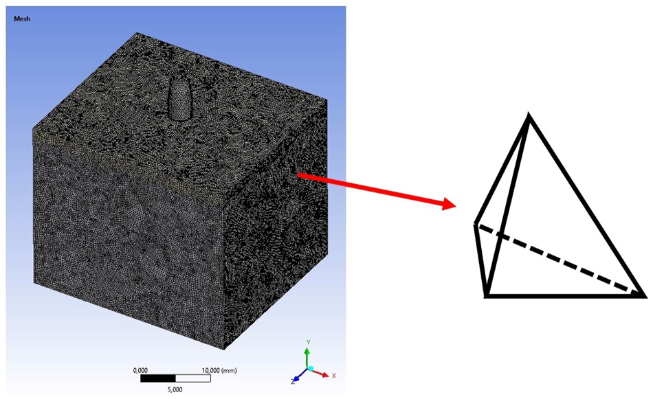
Detailed view of a tetrahedral mesh applied to solid body.
In the structure shown in Figure 1, due to the excess number of mesh unit elements, memory insufficiency occurred. For this reason, the full model was reduced to a quarter model, thus saving memory and time. The full model was divided from the symmetrical surfaces and symmetrical regions were defined on the cutting surfaces. The symmetrical surfaces are seen in Figure 2.
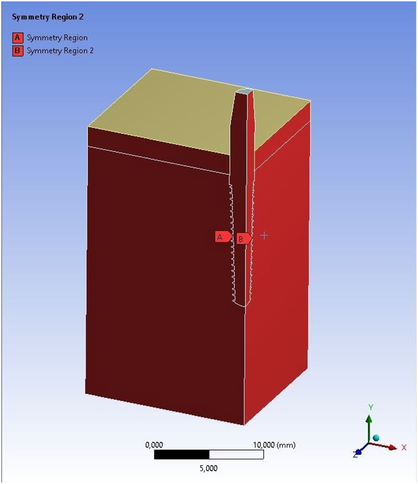
Symmetric boundary conditions in finite element model.
Table 1 shares the mesh quality values shared in the reference study and the results obtained in this study to demonstrate the suitability of the model and mesh structure. Skewness is the amount of distortion in a mesh element relative to its ideal shape [30]. It refers to the differences between the corner angles of a mesh element. A high skewness can cause stress concentrations, reducing the accuracy of the analysis. As the skewness decreases, the elements become more ideal, which provides more accurate results. A skewness value of less than 0.25 is considered excellent, between 0.25 and 0.5 is acceptable, and greater than 0.5 can be considered a poor-quality mesh. Orthogonal quality indicates how close the corner angles of an element are to 90°. In rectangular or square elements, the corner angles must be 90°. This criterion evaluates the corner angles of the element. An increase in orthogonal quality indicates that a higher-quality mesh structure is formed. For orthogonal quality, which takes values between 0 and 1, 0 is the worst and one shows the best result. According to the results obtained, very close values were reached with the reference study, and the mesh can give accurate results.
Mesh quality comparison.
| Reference [21] | Current study | |
|---|---|---|
| Maximum skewness | < 0.95 | 0.96 |
| Average skewness | < 0.33 | 0.21 |
| Minimum orthogonal quality | 0.06 | 0.04 |
| Average orthogonal quality | 0.81 | 0.79 |
Figure 3 shows the mesh structures and loading conditions of the quarter model. The obtained quarter model contains 2,056,183 elements and 2,829,369 nodes. The quarter model mesh structure, the dental implant mesh detail, the mesh detail of the bone surface in contact with the dental implant, and the quarter model FEA boundary conditions can be observed in detail. In the boundary conditions visual, a fixed support is defined for the blue surfaces, and a positive force is determined on the Y axis for the surface visible in red.
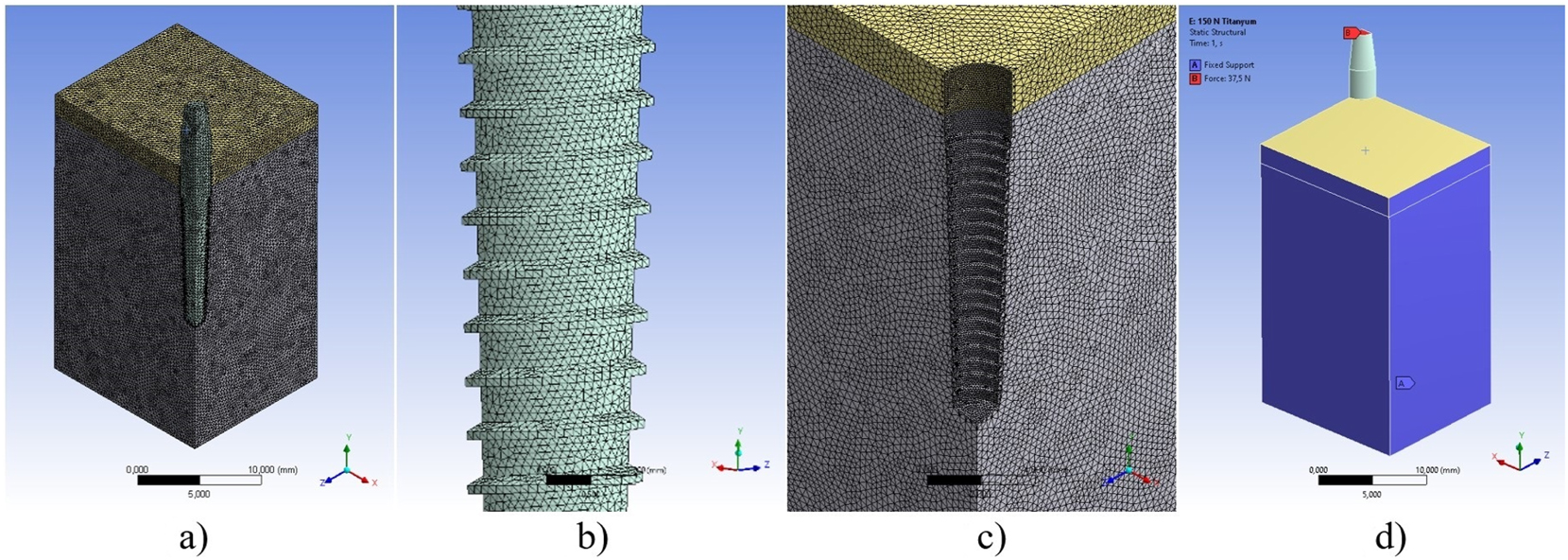
Pre-processing steps in FEA of a bone-implant system, a) mesh structure of quarter FEA model, b) mesh detail of implant, c) mesh detail of bone, d) boundary conditions of FEA model.
One quarter of the loading values specified in the reference study were applied to the quarter implant model obtained from the full model. As a result of the FEA performed, the graph resulting from the equivalent stress in megapascal (MPa) and forces in newton (N) units according to the von-Mises criteria is shared in Figure 4. It is seen that very close results are obtained with the stress values obtained in the reference study.
![Figure 4:
Load-dependent von mises stress comparison for model verification [21].](/document/doi/10.1515/mt-2024-0426/asset/graphic/j_mt-2024-0426_fig_004.jpg)
Load-dependent von mises stress comparison for model verification [21].
Figure 5 shows the stress distribution of the quarter model under axial 150 N. Visual inspection revealed that the stress distribution in the implant model was also quite compatible with the reference study.
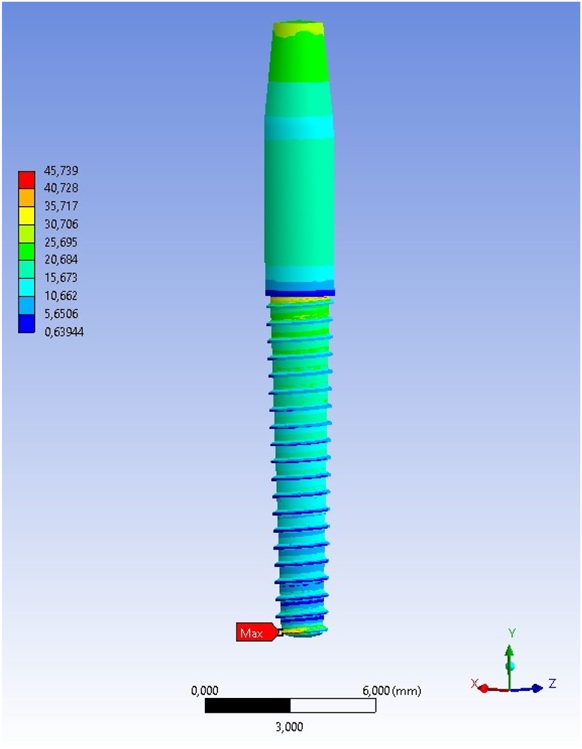
von mises stress (MPa) distribution of the implant under 150 N axial load.
2.2 Materials
The properties of five different materials, titanium alloy (Ti–6Al–4V), magnesium (ZK60 and WE43), hydroxyapatite (HA), and tantalum (Ta), which are frequently used in biomedical studies, were investigated on the implant model, which has been proven to be suitable numerically. The properties obtained from the relevant references are presented in Table 2.
Material properties.
| Ti–6Al–4V [21], [31] | ZK60 [31] | WE43 [32] | HA [33], [34] | Ta [35], [36], [37] | |
|---|---|---|---|---|---|
| Density (kg m−3) | 4,430 | 1800 | 1840 | 3,156 | 16,650 |
| Young’s modulus (MPa) | 105,000 | 44,300 | 45,000 | 90,000 | 163,500 |
| Poisson ratio | 0.35 | 0.35 | 0.35 | 0.30 | 0.36 |
| Yield tensile strength (MPa) | 862 | 240 | 199 | 100 | 220 |
| Ultimate tensile strength (MPa) | 931 | 315 | – | – | 310 |
2.3 Biomechanical performance criteria
The criteria considered in the biomechanical evaluation of materials include lightness, durability, relative movement, and penetration. The specified criteria were evaluated in three different MCDM methods together with the numerical results obtained from the FEA. The material presenting the highest score was selected as the most suitable material for the dental model. Explanations of the criteria considered in the evaluation are given below.
Lightness is important for biomechanical suitability and patient satisfaction [38], and obtaining the lightest implant model is a measure of success.
Functional durability effectively reduces the frequency of maintenance or repairs to obtain implants with long service life. According to the selected material technical specifications, the model with the low stress value and high safety factor resulted in the material being preferable.
Relative movement in bone-implant contact is effective in osseointegration. Studies in the literature [39], [40] have suggested that micro motion should not exceed 150 μm for healthy osseointegration. Additionally, according to Wolff’s law, it is stated that a stress value within a certain range accelerates bone formation [41]. A successful implant should have a low micro motion.
Implants under load can move independently of the bone tissue due to relative movement. In a good implant integration, the implant under load should not penetrate the bone and keep the stability. For this reason, low penetration and deformation are a criterion that increases implant success.
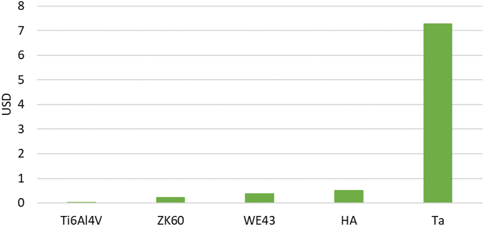
Although cost is not the main criterion in many academic studies, it is an important factor for a product offered to the public. In the study, material costs were also included among the assessment criteria in addition to biomechanical assessments. The prices of the materials assessed in the study were Ti–6Al–4V 47 USD kg−1 [42], ZK60 832.5 USD kg−1 [43], WE43 1332 USD kg−1 [44], HA 1070 USD kg−1 [45], Ta 2,930.4 USD kg−1 [46], respectively. In the dental implant cost calculation, the price of the materials, the material density, and the dental implant volume were used to obtain the results.
2.4 MCDM
The criteria taken into consideration in determining the most suitable material for dental implants were evaluated with MCDM methodologies. Weighted sum model (WSM) [47], technique for order of preference by similarity to ideal solution (TOPSIS) [48], and analytic hierarchy process (AHP) [49] methods frequently used in the literature were included in this study. Each method scored the dental implant material evaluation criteria, and the resulting scores were compared. In this way, the results of different methods were presented together, and the obtained result was strengthened.
WSM is one of the MCDM methods and is based on the evaluation of each criterion by weighting it. In this method, each alternative is scored according to the specified criteria, and a total score is calculated by multiplying these scores by the specified weights. The alternative with the highest total score is determined as the best option. The WSM steps followed in the study are as follows.
In Equation (1), each criterion is given weight based on its importance. Weights are usually expressed as a percentage and the total weight of all criteria should be 1. Here, wi represents the weight of each criterion.
In Equation (2), to compare criteria in different units, they are normalized. In cases where the maximum/minimum value of the criterion is better, the following formulas are used. In the equation, rij is the normalized value of the alternative for the jth criterion, xij is the original value of the alternative in the jth criterion, xmax and xmin are the maximum and minimum values of the relevant criterion.
In Equation (3), the normalized value of each criterion is multiplied by the weight of that criterion, and the weighted sum of all criteria is taken. Alternatives are ranked according to their total scores. The alternative with the highest score is selected as the most suitable option.
TOPSIS is another MCDM method. In this method, each alternative is evaluated according to its distance from both the ideal solution (best) and the anti-ideal solution (worst). The alternative is closest to the ideal solution and farthest from the anti-ideal solution it is selected as the best option. The TOPSIS calculation stages are as follows.
In Equation (4), the criteria are normalized, and all criteria are made comparable. rij is the normalized value of the alternative for the jth criterion, while xij is the original value of the alternative at the jth criterion.
In Equation (5), the normalized value of each criterion is multiplied by the weight of that criterion. vij is the weighted normalized value of the alternative for the jth criterion, wj is the weight of the jth criterion.
In Equation (6), the distances to the positive and negative ideal solutions for each alternative are calculated with the following formulas.
In Equation (7), the closeness score to the ideal solution is calculated for each alternative. Ci is the TOPSIS score of the ith alternative, di+ is the distance to the positive ideal solution, and di− is the distance to the negative ideal solution. The alternatives are ranked according to their Ci scores. The alternative with the highest score is selected as the best.
Another decision-making method, AHP, is based on the comparison of criteria and alternatives in a hierarchical structure. Results are produced from a decision matrix by evaluating the relative importance of criteria and alternatives. In the AHP method, the decision problem is modeled as a hierarchical structure. The main goal of the decision is at the first level, the criteria are at the second level, and the alternatives are at the third level. Criteria and alternatives are compared pairwise with each other in a pairwise comparison matrix. The comparison is made using a scale from one to 9. In comparison, one indicates equal importance, three indicates a criterion is slightly more important than the other, five indicates a criterion is much more important than the other, seven indicates a criterion is extremely important than the other, and nine indicates a criterion is more important than the other. An example of the matrix created is in Equation (8).
In Equation (9), the geometric mean of each row in the comparison matrix is taken to find the weight of each criterion. Wi, geometric mean of the ith criterion, aij, relative importance of the ith criterion to the jth criterion in the comparison matrix, n, dimension of the comparison matrix.
In Equation (10), the normalized weight of each criterion is calculated as follows. Here wi represents the normalized weight of the ith criterion.
Equation (11) involves calculating the total score. Ri is the total score of the ith alternative, wj is the weight of the jth criterion, rij is the normalized value of the ith alternative on the jth criterion.
2.5 Design improvement
In biomedical implants, implant-bone compatibility is important for lifespan and patient health. Biomechanically, the low relative movement between the bone and the implant prevents the formation of a stress shield. In approaches to reducing relative movement, material selection close to bone properties or design changes provides solutions. In this study, microgrooves were added to the dental implant model for which optimum material selection was made to improve osseointegration. The dimensions of the micro-grooves added with the expectation of reducing the relative movement between the bone and the implant are 0.1 mm in depth and 0.1 mm in width, based on [50], [51], [52]. Micro grooves were designed with a square cross-section and were placed between two screw threads in the dental implant model. The dental implant model with micro-grooves can be seen in Figure 6. For the dental implant model with osseo-healing design changes, FEA was repeated with the same boundary conditions, and stress, deformation, sliding distance, and penetration measurements were made on the same points.
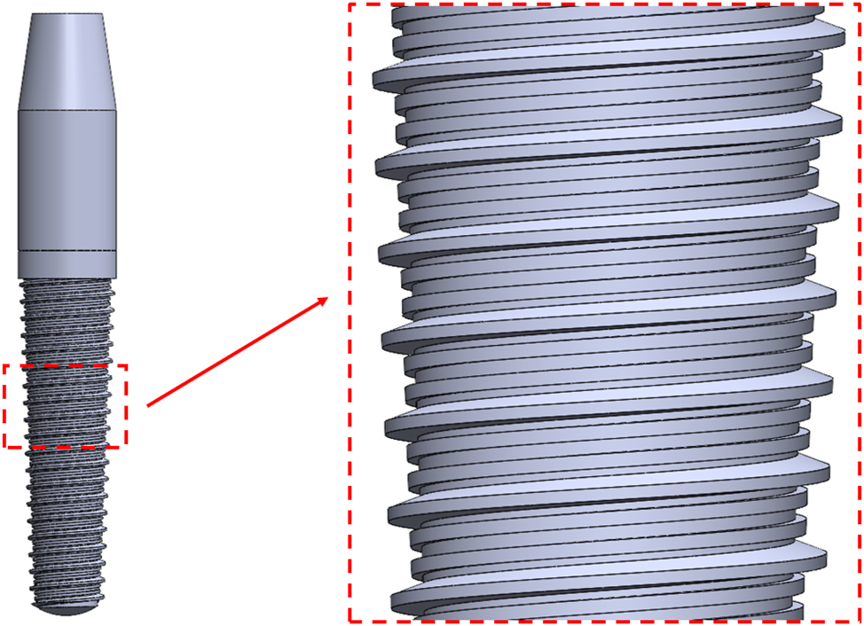
Geometric design and thread detail of the implant model.
3 Results
In this study, the optimal material determination was made among five different materials under four different loadings for a dental screw implant. Mechanical behaviors were simulated with the help of FEA. The obtained results were evaluated regarding lightness, strength, and osseointegration. In the examination of lightness, the implant masses in gram (g) were 0.638 g for Ti–6Al–4V, 0.259 g for ZK60, 0.265 g for WE43, 0.454 g for HA, and 2.40 g for Ta. According to these results, the dental implant using the ZK60 will have the lightest structure.
Figures 7 and 8 shows maximum stress values according to the Von Mises criteria and safety factors, respectively. In these results, the stress increase and the safety factor decrease occurred with the increase in force. Compared with other materials in maximum stress values, ZK60 and WE43 had higher values, while HA had the lowest stress value. In the safety factors, the order from bad to good is HA, WE43, Ta, ZK60, and Ti6Al4V. According to the functional durability assessment, Ti6Al4V was able to create the most optimistic picture.
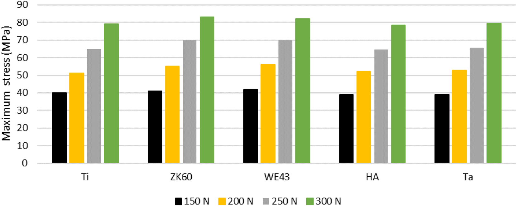
Stress performance of materials under axial loading.
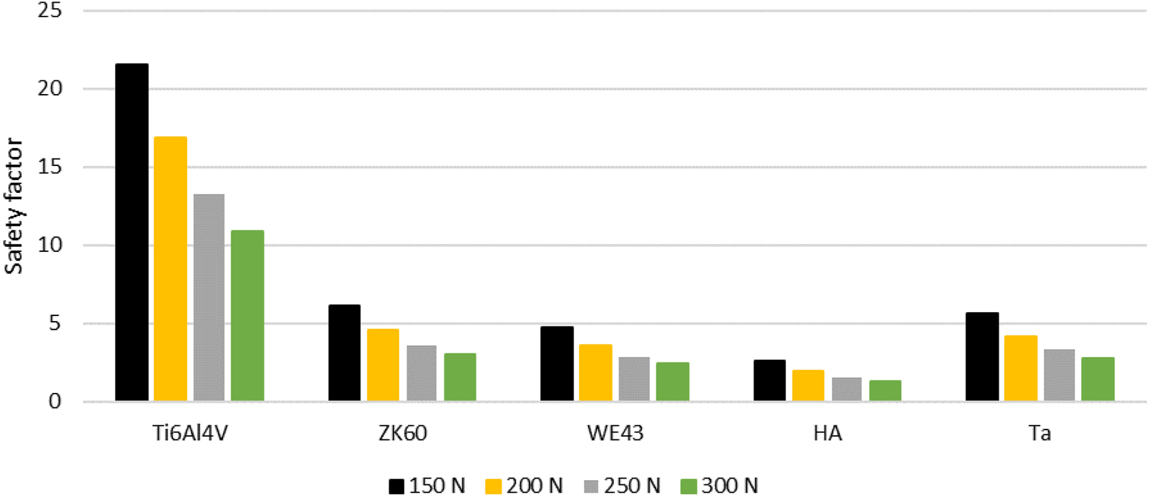
Load-dependent structural safety assessment of implant materials.
In the osseointegration evaluation, deformation, sliding distances and penetration values at the implant-bone interface are shown in Figures 9, 10, and 11, respectively. It is shown that there is an increase in the deformation values in Figure 9 parallel to the increase in force. However, the Ta gave the lowest deformation result under forces. The sliding distances in Figure 10 show the relative movement value between the bone and the implant. While the sliding values were similar in all material types, ZK60 and WE43 gave higher results. All materials were successful in meeting the micro movement criteria. The penetrations in Figure 11 show how far the implant penetrates the bone surface under loading. Similar to the sliding movement, ZK60, and WE43 dental implants penetrated more into the bone.
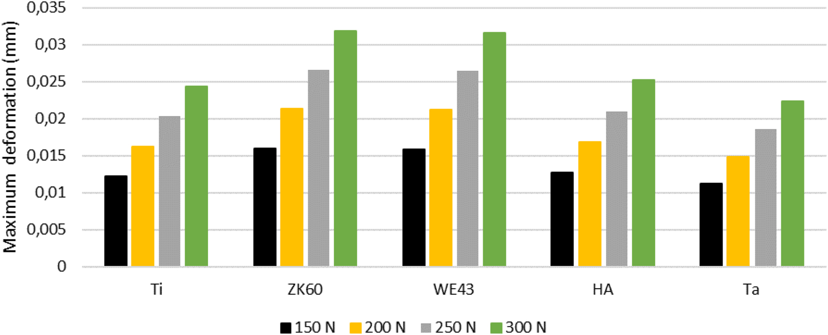
Deformation behavior of materials at varying load levels.
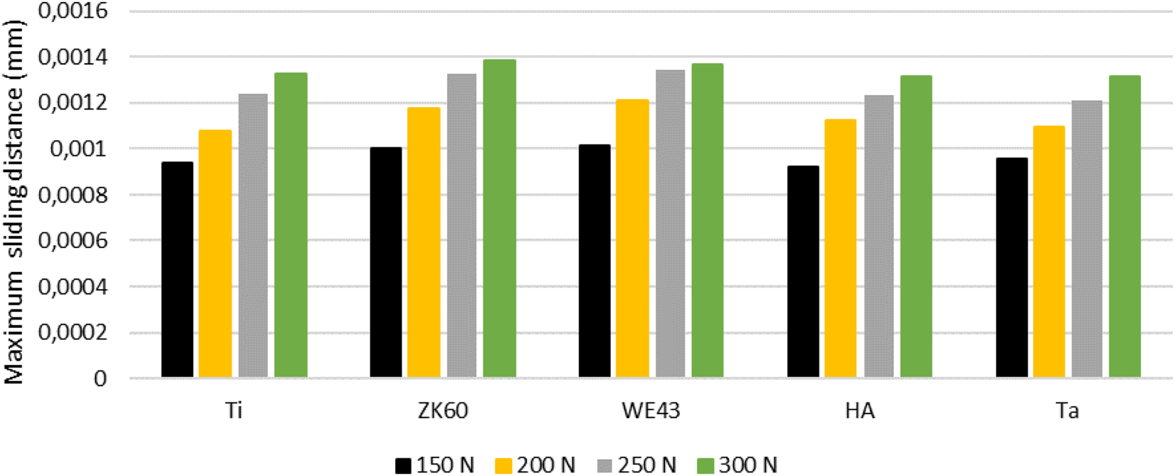
Contact surface sliding evaluation in implant models.
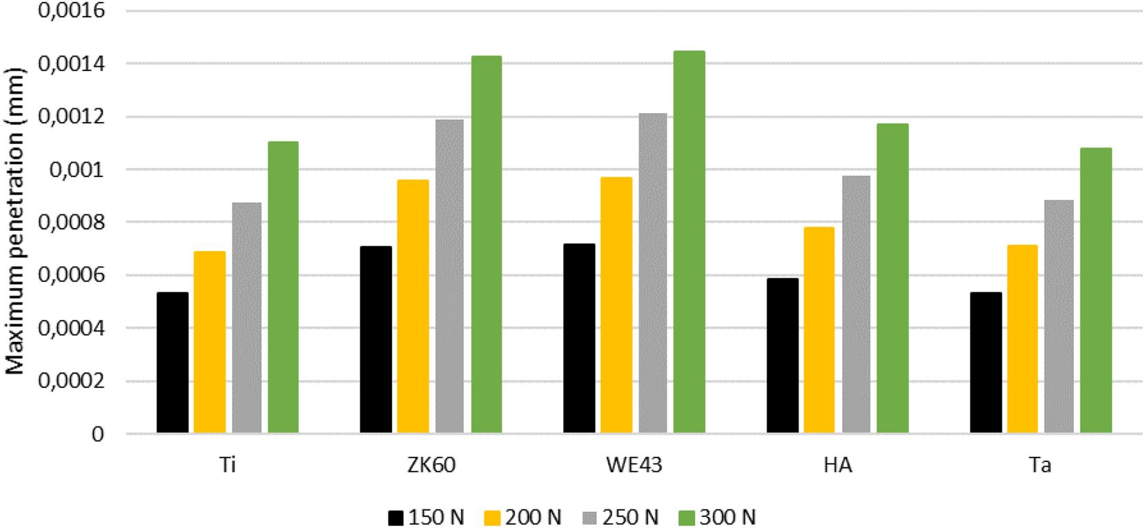
Maximum surface penetration depths in contact zones of biomaterials.
Figure 12 shows the results of the calculated piece cost based on the unit prices of the materials. All materials except Tantalum cost less than 1 USD. According to these results, Ti6Al4V can offer the most cost-effective dental implant model, while Ta is the most expensive. The remaining ZK60, WE43, and HA have approximately similar cost results.
Material-based cost analysis for dental implant applications.
3.1 MCDM results
Five materials were evaluated in terms of their biomechanical suitability for the dental implant model with the help of WSM, TOPSIS, and AHP, among the MCDM methods. The effect rates of the lightness (kg), functional durability, relative mobility (mm), penetration (mm), and cost (USD) criteria considered in the study are equal. The results obtained according to four different loading conditions are shown in Figure 13. According to the scores obtained in the MCDM methods, magnesium alloy Ti6Al4V stood out as the most suitable material for the dental implant model by receiving the highest score in three different MCDM methods. On the other hand, Ta was ranked last by obtaining the lowest score. Other materials were ranked high to low: HA, ZK60, and WE43.
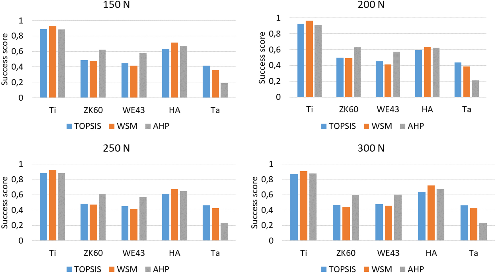
Success score evaluation using MCDM for implant material selection.
The FEA result images of the Ti6Al4V dental implant, which was selected as the most suitable material for the dental implant by receiving the highest score in three different MCDM methods, are in Figure 14. Figure 14 shows the stress distribution, deformation distribution, relative mobility in the bone-implant contact, and the amount of embeddedness of the dental implant in the bone underload according to the von Mises criterion. In the evaluation of FEA results, high-value results containing singularities were not considered.
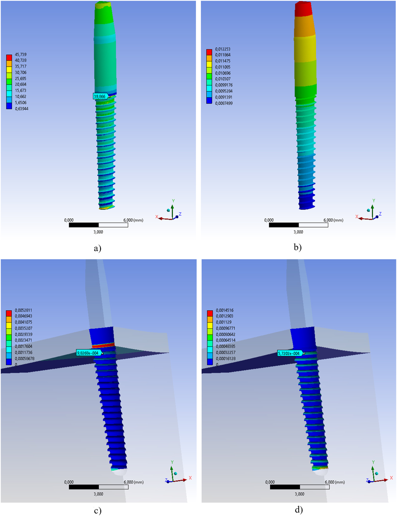
Biomechanical analysis results of Ti6Al4V implant, a) equivalent stress (MPa), b) total deformation (mm), c) sliding distance (mm), d) penetration depth (mm).
3.2 Design improvement results
The dental implant model with osseointegration enhancer micro-grooves was subjected to FEA with the same boundary conditions as the model without grooves. Maximum stress, maximum deformation, maximum sliding distance, and maximum penetration results in the implant structure under 150 N, 200 N, 250 N, and 300 N were obtained and shown in Tables 3, 4, 5, and 6, respectively. In the results obtained, it was seen that the groove had a reducing effect on the sliding distance and penetration.
FEA results comparison under the 150 N.
| Non-grooved | Grooved | |
|---|---|---|
| Maximum stress (MPa) | 40.01 | 39.96 |
| Maximum deformation (mm) | 0.0122 | 0.0120 |
| Sliding distance (mm) | 0.00094 | 0.000862 |
| Maximum penetration (mm) | 0.000532 | 0.000317 |
FEA results comparison under 200 N.
| Non-grooved | Grooved | |
|---|---|---|
| Maximum stress (MPa) | 51.20 | 52.754 |
| Maximum deformation (mm) | 0.0162 | 0.0159 |
| Sliding distance (mm) | 0.00108 | 0.00107 |
| Maximum penetration (mm) | 0.000685 | 0.000395 |
FEA results comparison under 250 N.
| Non-grooved | Grooved | |
|---|---|---|
| Maximum stress (MPa) | 65.10 | 66.66 |
| Maximum deformation (mm) | 0.0203 | 0.0199 |
| Sliding distance (mm) | 0.00124 | 0.00123 |
| Maximum penetration (mm) | 0.000876 | 0.000501 |
FEA results comparison under the 300 N.
| Non-grooved | Grooved | |
|---|---|---|
| Maximum stress (MPa) | 79.20 | 78.54 |
| Maximum deformation (mm) | 0.0243 | 0.02385 |
| Sliding distance (mm) | 0.00133 | 0.001245 |
| Maximum penetration (mm) | 0.0011 | 0.000512 |
Figure 15 shows the percentage results of the positive effect of microgroove on the sliding distance and penetration under different loadings. The penetration improvement rate became better with the increase of force. However, the same behavior was not observed for sliding distance. The penetration improvement rates were between 40 % and 53 %, while the sliding distance improvement rates were between 0.8 % and 8.3 %.
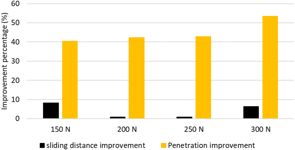
Percentage improvement in sliding distance and penetration depth at various loading conditions.
Figure 16 visualizes the FEA stress, deformation, sliding distance, and penetration results of a micro-threaded dental implant under 150 N. The measured points are included in the images to make the evaluation objective. The maximum values on the scales in the images are not considered because they occur in very small areas.
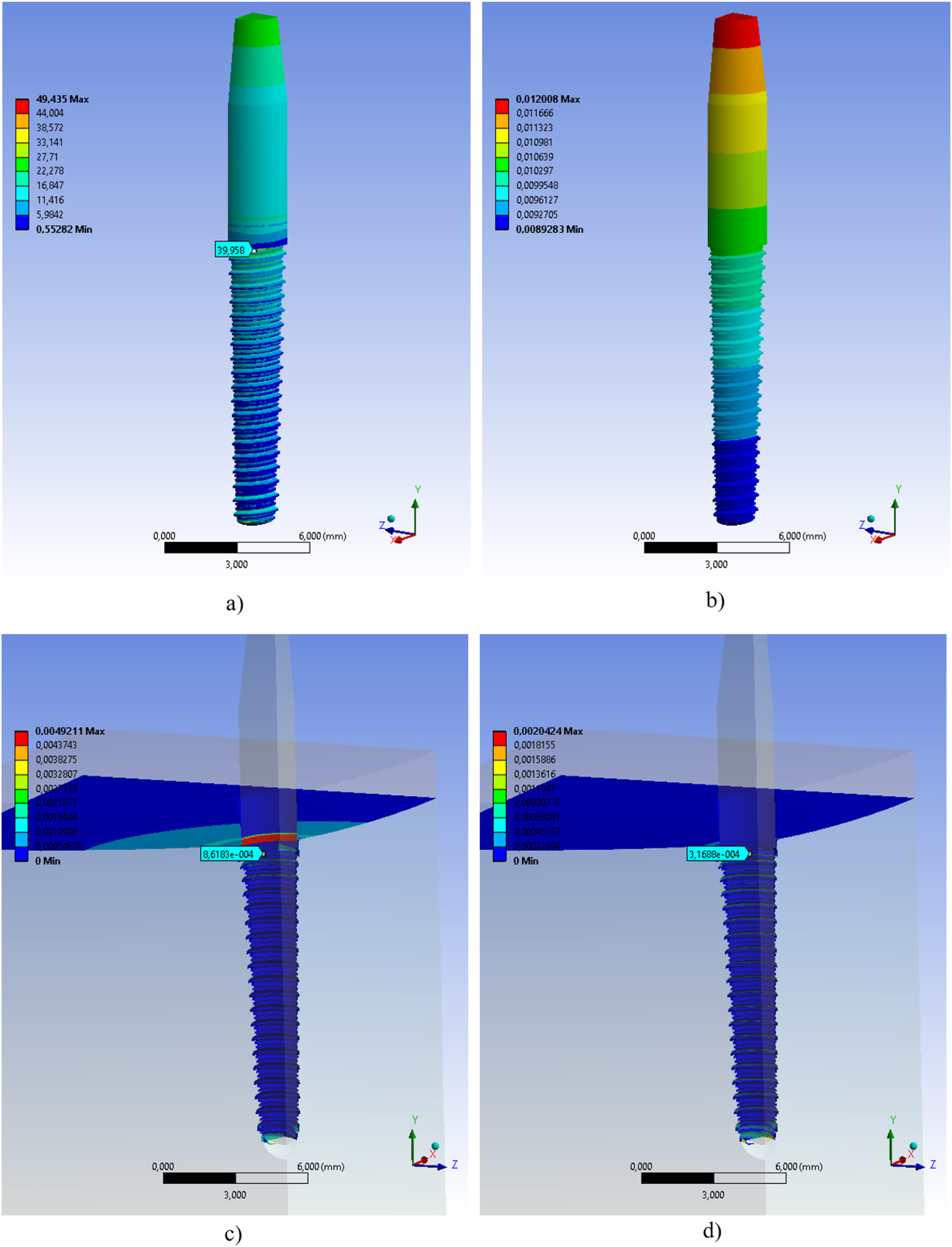
Biomechanical assessment results of the micro-grooved dental implant with Ti6Al4V, a) equivalent stress (MPa) distribution, b) deformation (mm) distribution, c) sliding (mm) distribution, d) penetration (mm) distribution.
4 Conclusions
In this study, results supporting biomechanical evaluation were obtained using finite element analysis (FEA) to determine the appropriate material for dental implants. According to the comprehensive evaluation, the most appropriate material was determined as Ti6Al4V using three different MCDM methods. It is not surprising that Ti6Al4V stands out among other materials because it is a frequently preferred material in biomedical applications with its lightness, biocompatibility, mechanical strength, and low cost. In addition, its suitability for additive manufacturing technology shows that this material is open to new technologies. Other results obtained in the study revealed that the sliding distance and penetration increased significantly as the force increased and showed a positive relationship between sliding distance, deformation, and penetration.
According to the FEA results, micro-threaded implants provide significant improvements compared to unthreaded implants, especially in terms of penetration performance. Threaded implants show lower maximum penetration values at all force levels, indicating that osseointegration can be achieved better and the implant can be more tightly integrated into the bone. In addition, penetration improvement increased as the force increased. This will increase implant stability and reduce the risk of failure in the long term. No significant difference was observed between threaded and unthreaded implants in terms of sliding distance, but there was a slight improvement. In terms of maximum stress and deformation values, it was observed that micro-threads did not negatively affect the structural integrity and durability of the implant, and the stress and deformation rates remained largely constant. As force levels increased, the penetration advantage of micro-threaded implants became more apparent.
This study provides a comprehensive assessment including the most appropriate material selection for dental implants and also reveals some important points that can guide future studies. The data obtained with powerful methods such as FEA in the study, if supported by clinical experiments, can better reflect the real-world behavior of materials. Osseointegration plays a critical role in the success of dental implants, and more comprehensive clinical studies or simulations would be beneficial. Furthermore, the inclusion of more materials could broaden the scope of the study and provide more generally valid results. Factors such as manufacturing processes, costs, and application difficulties should also be included in the cost analysis. It should also be noted that dental implants may exhibit different performance under dynamic loading, and this should be taken into account to fully assess the long-term success of the implant.
About the authors
Efe Savran, born in 1993. He received B.Sc. from Balikesir University. Currently, he is a PhD candidate in the mechanical engineering department of Bursa Uludag University. As a scholarship holder of The Scientific and Technological Research Council of Turkey (TUBITAK), he is a co-worker of Karsan Automotive. His interest areas are electrified powertrains, energy-efficient driving analysis, biomedical applications, and finite element methods. He has national and international academic publications in his research areas.
Prof. Dr. Fatih Karpat, born in 1977, Professor Dr. at the Mechanical Engineering department at Bursa Uludag University. He received his BSc in 1998, MSc in 2001, and PhD in 2005 from Bursa Uludag University. He joined the academic community as a research assistant in 1998 and he continued his success by gaining the title of associate professor in 2015 and professor in 2020. He has been to Texas Tech University and the University of Central Oklahoma between 2006 and 2015 as a postdoctoral and guest researcher. His professions are based on machine elements, biomedical engineering, sustainability, and MEMS. He has more than 20 science citation-indexed publications, 5 book chapters, and more than 70 academic conference publications. Besides the academic side, he also managed more than 20 industrial projects.
Acknowledgments
The authors are presenting their appreciation to TUBITAK (project code 119C154) the support in the preparation of this study.
-
Research ethics: Not applicable.
-
Informed consent: Not applicable.
-
Author contributions: The authors have accepted responsibility for the entire content of this manuscript and approved its submission.
-
Use of Large Language Models, AI and Machine Learning Tools: None declared.
-
Conflict of interest: The authors state no conflict of interest.
-
Research funding: TUBITAK (project no: 119C154).
-
Data availability: The raw data can be obtained on request from the corresponding author.
References
[1] J. W. Nicholson, “Titanium alloys for dental implants: a review,” Prosthesis, vol. 2, no. 1, pp. 100–116, 2020, https://doi.org/10.3390/prosthesis2020011.Search in Google Scholar
[2] P. Andrea, L. Caneiro Queija, S. Mareque, A. Tasende Pereira, A. Liñares González, and J. Blanco Carrión, “Titanium vs ceramic single dental implants in the anterior maxilla: a 12-month randomized clinical trial,” Clin. Oral Implants Res., vol. 32, no. 8, pp. 951–961, 2021, https://doi.org/10.1111/clr.13788.Search in Google Scholar PubMed
[3] O. Charyeva, O. Dakischew, U. Sommer, C. Heiss, R. Schnettler, and K. Susanne, “Biocompatibility of magnesium implants in primary human reaming debris derived cells stem cells in vitro,” J. Orthop. Traumatol., vol. 17, no. 1, pp. 63–73, 2016, https://doi.org/10.1007/s10195-015-0364-9.Search in Google Scholar PubMed PubMed Central
[4] J. D. C. Tardelli, M. L. C. Valente, A. P. Macedo, and A. C. Reis, “Evaluation of biomechanical and stress distribution of different dental implant designs : primary stablity and photoelastic analysis,” IRBM, vol. 43, no. 2, pp. 100–106, 2022, https://doi.org/10.1016/j.irbm.2021.01.003.Search in Google Scholar
[5] S. Kligman, Z. Ren, C. H. Chung, “The impact of dental implant surface modifications on osseointegration and biofilm formation,” J. Clin. Med., vol. 10, no. 1641, pp. 1–36, 2021, https://doi.org/10.3390/jcm10081641.Search in Google Scholar PubMed PubMed Central
[6] M. Alpar, E. Savran, and F. Karpat, “Anti-roll bar optimization of an urban electric bus,” Arch. Adv. Eng. Sci., pp. 1–8, 2024, https://doi.org/10.47852/bonviewAAES42022250.Search in Google Scholar
[7] M. K. Turan, C. Ensarioglu, A. Bakirci, and F. Karpat, “Impact performance of unconventional trigger holes,” Mater. Test., vol. 66, no. 3, pp. 389–396, 2024, https://doi.org/10.1515/mt-2023-0253.Search in Google Scholar
[8] M. Eskibaǧlar, S. Erdem, M. O. Kaman, and M. S. Ocak, “Finite element analysis of bending and torsional loading of two different endodontic rotary files with different off-center geometric sections,” Mater. Test., vol. 65, no. 11, pp. 1707–1712, 2023, https://doi.org/10.1515/mt-2023-0070.Search in Google Scholar
[9] O. İyibilgin, E. Gepek, L. Bayam, E. Drampalos, and A. Shoaib, “Pull-out strength of screws in long bones at different insertion angles: finite element analysis and experimental investigations,” Mater. Test., vol. 66, no. 3, pp. 380–388, 2024, https://doi.org/10.1515/mt-2023-0239.Search in Google Scholar
[10] O. Dogan, C. Yuce, and F. Karpat, “Effects of rim thickness and drive side pressure angle on gear tooth root stress and fatigue crack propagation life,” Eng. Fail. Anal., vol. 122, no. 105260, pp. 1–18, 2021, https://doi.org/10.1016/j.engfailanal.2021.105260.Search in Google Scholar
[11] M. K. Turan, C. Yuce, and F. Karpat, “Numerical and experimental investigation of the effect of heat input on weld bead geometry and stresses in laser welding,” Mater. Test., vol. 66, no. 9, pp. 1463–1474, 2024, https://doi.org/10.1515/mt-2024-0080.Search in Google Scholar
[12] D. Kluess, H. E. Lange, H. Heyer, W. Sander, M. Manuela, and R. Bader, “Supplementary finite element analysis in experimental testing of total hip stems,” Mater. Test., vol. 60, no. 5, pp. 489–494, 2018, https://doi.org/10.3139/120.111182.Search in Google Scholar
[13] F. N. Büyük, E. Savran, and F. Karpat, “Review on finite element analysis of dental implants,” J. Dent. Implant Res., vol. 41, no. 3, pp. 50–63, 2022, https://doi.org/10.54527/jdir.2022.41.3.50.Search in Google Scholar
[14] A. B. Karakullukcu, E. Taban, and O. O. Ojo, “Biocompatibility of biomaterials and test methods: a review,” Mater. Test., vol. 65, no. 4, pp. 545–559, 2023, https://doi.org/10.1515/mt-2022-0195.Search in Google Scholar
[15] P. Kumar, N. Kumar, and S. Jaiswal, “Development of Ti-Ta-Nb-Mo-Zr high entropy alloy by m-plasma arc additive manufacturing process for knee implant applications and its biocompatibility evaluation,” J. Mater. Res. Technol., vol. 22, no. 1, pp. 541–555, 2022, https://doi.org/10.1016/j.jmrt.2022.11.167.Search in Google Scholar
[16] Y. P. Dong, J. Tang, D. Wang, “Additive manufacturing of pure Ti with superior mechanical performance, low cost, and biocompatibility for potential replacement of Ti-6Al-4V,” Mater. Des., vol. 196, no. 109142, pp. 1–14, 2020, https://doi.org/10.1016/j.matdes.2020.109142.Search in Google Scholar
[17] H. Li, J. Wen, Y. Liu, J. He, H. Shi, and P. Tian, “Progress in research on biodegradable magnesium alloys: a review,” Adv. Eng. Mater., vol. 22, no. 7, pp. 1–16, 2020, https://doi.org/10.1002/adem.202000213.Search in Google Scholar
[18] P. Kazimierczak and A. Przekora, “Osteoconductive and osteoinductive surface modifications of biomaterials for bone regeneration: a concise review,” Coatings, vol. 10, no. 971, pp. 1–25, 2020, https://doi.org/10.3390/coatings10100971.Search in Google Scholar
[19] L. Chen, S. Al-bayatee, Z. Khurshid, A. Shavandi, P. Brunton, and J. Ratnayake, “Hydroxyapatite in oral care products – a review,” Materials (Basel), vol. 14, no. 4865, pp. 1–20, 2021, https://doi.org/10.3390/ma14174865.Search in Google Scholar PubMed PubMed Central
[20] D. Alontseva, Y. Safarova Yantsen, S. Voinarovych, “Biocompatibility and corrosion of microplasma-sprayed titanium and tantalum coatings versus titanium alloy,” Coatings, vol. 14, no. 206, pp. 1–23, 2024, https://doi.org/10.3390/coatings14020206.Search in Google Scholar
[21] O. C. Kalay, et al., “A comparative 3d finite element computational study of stress distribution and stress transfer in small-diameter conical dental implants,” Teh. Vjesn., vol. 28, no. 6, pp. 2045–2054, 2021, https://doi.org/10.17559/TV-20200518180158.Search in Google Scholar
[22] I. Roatesi and S. Roatesi, “Biomechanics study of dental implant - bone system by finite element method,” J. Brazilian Soc. Mech. Sci. Eng., vol. 45, no. 6, pp. 1–9, 2023, https://doi.org/10.1007/s40430-023-04170-5.Search in Google Scholar
[23] J. Lee, H. Y. Jang, and S. Y. Lee, “Finite element analysis of dental implants with zirconia crown restorations: conventional cement-retained vs. Cementless screw-retained,” Materials (Basel), vol. 14, no. 2666, pp. 1–10, 2021, https://doi.org/10.3390/ma14102666.Search in Google Scholar PubMed PubMed Central
[24] M. C. R. Ibrahim, S. Ahmed, and O. Askar, “A finite element analysis study on different angle correction designs for inclined implants in All-On-Four protocol,” BMC Oral Health, vol. 24, no. 331, pp. 1–14, 2024.10.1186/s12903-024-04091-2Search in Google Scholar PubMed PubMed Central
[25] P. Dhatrak, V. Girme, U. Shirsat, S. Sumanth, and V. Deshmukh, “Significance of orthotropic material models to predict stress around bone-implant interface using numerical simulation,” Bionanoscience, vol. 9, no. 1, pp. 652–659, 2019, https://doi.org/10.1007/s12668-019-00649-5.Search in Google Scholar
[26] L. Paracchini, C. Barbieri, M. Redaelli, D. Di Croce, C. Vincenzi, and R. Guarnieri, “Finite element analysis of a new dental implant design optimized for the desirable stress distribution in the surrounding bone region,” Prosthesis, vol. 2, no. 3, pp. 225–236, 2020, https://doi.org/10.3390/prosthesis2030019.Search in Google Scholar
[27] I. Roatesi and S. Roatesi, “Modeling of dental implant osseointegration progress by three-dimensional finite element method,” Appl. Sci., vol. 10, no. 5561, pp. 1–12, 2020, https://doi.org/10.3390/app10165561.Search in Google Scholar
[28] H. Choi and M. H. Hong, “Finite element analysis of the effect of tightening torque on the connection stability of a two-piece zirconia implant system,” Adv. Mater. Sci. Eng., vol. 2022, no. 5, pp. 1–10, 2022, https://doi.org/10.1155/2022/1456475.Search in Google Scholar
[29] Y. Wang, X. Chen, C. Zhang, “Studies on the performance of selective laser melting porous dental implant by finite element model simulation , fatigue testing and in vivo experiments,” Proc. Inst. Mech. Eng. Part H J. Eng. Med., vol. 233, no. 2, pp. 170–180, 2019, https://doi.org/10.1177/0954411918816114.–Search in Google Scholar PubMed
[30] I. Ansys, “ANSYS meshing user’s guide,” vol. 15317, pp. 724–746, 2013.Search in Google Scholar
[31] E. Savran, O. C. Kalay, N. B. Alp, and F. Karpat, “Design and analysis of lattice structure applied humerus semi-prosthesis,” Mater. Test., vol. 65, no. 7, pp. 1–17, 2023, https://doi.org/10.1515/mt-2022-0408.Search in Google Scholar
[32] J. Chen, F. Dong, and S. Liu, “Design and mechanical performance evaluation of WE43 magnesium alloy biodegradable stents via finite,” Metals (Basel)., vol. 14, no. 704, pp. 1–14, 2024, https://doi.org/10.3390/met14060704.Search in Google Scholar
[33] J. S. Al-sanabani, A. A. Madfa, and F. A. Al-sanabani, “Application of calcium phosphate materials in dentistry,” Int. J. Biomater., vol. 2013, no. 1, pp. 1–12, 2013, https://doi.org/10.1155/2013/876132.Search in Google Scholar PubMed PubMed Central
[34] M. W. Bilton, “Nanoparticulate hydroxyapatite and calcium - based CO2 sorbents,” Ph.D. Thesis, University of Leeds, Leeds, UK, 2012.Search in Google Scholar
[35] L. Thijs, M. L. M. Sistiaga, R. Wauthle, Q. Xie, J. Kruth, and J. Van Humbeeck, “Strong morphological and crystallographic texture and resulting yield strength anisotropy in selective laser melted tantalum,” Acta Mater., vol. 61, no. 12, pp. 4657–4668, 2013, https://doi.org/10.1016/j.actamat.2013.04.036.Search in Google Scholar
[36] D. Jiang, Q. Wang, W. Hu, Z. Wei, J. Tong, and H. Wan, “The effect of tantalum (Ta) doping on mechanical properties of tungsten (W): a first-principles study,” J. Mater. Res., vol. 31, no. 21, pp. 3401–3408, 2016, https://doi.org/10.1557/jmr.2016.358.Search in Google Scholar
[37] National Center for Biotechnology Information, “Compound summary for CID 23956, Tantalum,” PubChem [Online]. Available at: https://pubchem.ncbi.nlm.nih.gov/compound/Tantalum [accessed: Jan. 1, 2024].Search in Google Scholar
[38] M. P. Staiger, A. M. Pietak, J. Huadmai, and G. Dias, “Magnesium and its alloys as orthopedic biomaterials: a review,” Biomaterials, vol. 27, no. 9, pp. 1728–1734, 2006, https://doi.org/10.1016/j.biomaterials.2005.10.003.Search in Google Scholar PubMed
[39] N. Kohli, J. C. Stoddart, and R. J. Van Arkel, “The limit of tolerable micromotion for implant osseointegration: a systematic review,” Sci. Rep., vol. 11, no. 1, pp. 1–11, 2021, https://doi.org/10.1038/s41598-021-90142-5.Search in Google Scholar PubMed PubMed Central
[40] W. Winter, D. Klein, and M. Karl, “Micromotion of dental implants : basic mechanical considerations,” J. Med. Eng., vol. 2013, no. 265412, pp. 1–9, 2013, https://doi.org/10.1155/2013/265412.Search in Google Scholar PubMed PubMed Central
[41] L. Wang, X. You, L. Zhang, C. Zhang, and W. Zou, “Mechanical regulation of bone remodeling,” Bone Res., vol. 10, no. 1, pp. 1–15, 2022, https://doi.org/10.1038/s41413022-00190-4.Search in Google Scholar
[42] MSESupplies, “MSE PRO Ti-6Al-4V (TC4) titanium based metal powder for additive manufacturing,” [Online]. https://www.msesupplies.com/products/mse-pro-ti6al-4v-tc4-titanium-based-metalpowder-for-additive-manufacturing-3dprinting?variant=31729219174458 [accessed: Jan. 1, 2024].Search in Google Scholar
[43] Nanografi, “ZK60 magnesium alloy micron powder,” [Online]. https://nanografi.com/newly-released-products/zk60-magnesiumalloy-micronpowder-size-range-20-63-m-spherical/ [accessed: Jan 1, 2024].Search in Google Scholar
[44] Nanografi, “WE43 magnesium alloy,” [Online]. https://nanografi.com/microparticles/we43-magnesium-alloy-averageparticle-size-1553-um-spherical/?srsltid=AfmBOorjzJjFDV_t5FGRQ5iWhTDuWTsOdply7nO5H_eLaSCftwYiHKt [accessed: Jan. 1, 2024].Search in Google Scholar
[45] Sunumestore, “Hydroxyapatite (nanopowder),” [Online]. https://sunumestore.com/products/bioceramics/hydroxyapatitenanopowder/hydroxyapatite-nanopowder [accessed Jan 1, 2024].Search in Google Scholar
[46] Mateck, “Tantalum powder,” [Online]. https://mateck.com/en/tantalum/3760tantalum-powder-3760.html [accessed: Jan. 1, 2024].Search in Google Scholar
[47] P. Pesode, S. Barve, S. V. Wankhede, D. R. Jadhav, and S. K. Pawar, “Titanium alloy selection for biomedical application using weighted sum model methodology,” Mater. Today Proc., vol. 72, no. October, pp. 724–728, 2023, https://doi.org/10.1016/j.matpr.2022.08.494.Search in Google Scholar
[48] Z. Yue, “Extension of TOPSIS to determine weight of decision maker for group decision making problems with uncertain information,” Expert Syst. Appl., vol. 39, no. 7, pp. 6343–6350, 2012, https://doi.org/10.1016/j.eswa.2011.12.016.Search in Google Scholar
[49] K. Moiduddin, S. H. Mian, U. Umer, H. Alkhalefah, and A. Sayeed, “Fuzzy multicriteria decision mapping to evaluate implant design for maxillofacial reconstruction,” Mathematics, vol. 8, no. 12, pp. 1–33, 2020, https://doi.org/10.3390/math8122121.Search in Google Scholar
[50] Y. Sun, et al., “Mechanism of zirconia microgroove surface structure for osseointegration,” Mater. Today Adv., vol. 12, no. 100159, pp. 1–19, 2021, https://doi.org/10.1016/j.mtadv.2021.100159.,Search in Google Scholar
[51] M. Alkhodary, “Laser micro-grooved , Arginine-Glycine-Apspartic acid (RGD) coated dental implants , a 5 years radiographic follow-up,” Int. J. Health Sci. (Qassim)., vol. 8, no. 4, pp. 1–9, 2019, https://doi.org/10.12816/0023993.Search in Google Scholar
[52] M. Khandaker, A. Ait Moussa, D. N. Sama, “Laser-induced microgrooves improve the mechanical responses of cemented implant systems,” Micromachines, vol. 11, no. 466, pp. 1–15, 2020, https://doi.org/10.3390/mi11050466.Search in Google Scholar PubMed PubMed Central
© 2025 the author(s), published by De Gruyter, Berlin/Boston
This work is licensed under the Creative Commons Attribution 4.0 International License.
Articles in the same Issue
- Frontmatter
- Effect of flush grinding on corrosion fatigue behavior of step-aged 7020 aluminum alloys
- Bending behavior of corrugated sandwich panels with various core shapes
- Comparison of crash performance of auxetic structures for CF15, PA6/GF30, and GF30PP materials
- Combined effect of ball milling and high-pressure torsion on mechanical properties of Al2O3/Al composite
- Liquid metal embrittlement susceptibility of galvanized advanced high strength steel with high manganese content
- Kinetic study on nickel aluminides formed on Monel 400 alloy
- Finite element simulation of natural gas pipelines in service welding repair
- Biomechanical effects of material selection and micro-groove design for dental implants
- Design, FEA and experimental validation of 3D-printed PLA/PCL intervertebral cages for lumbar spinal fusion
- Effect of tool tilt angles on the formation of YSZ/Al2O3 hybrid surface composites on friction stir processed magnesium alloy AZ31
- Coating of AISI 304 stainless steel surface with addition of Cr3C2 to NiCrCo medium entropy alloy powder
- Numerical and analytical stress analysis for a FGM beam
- Mechanical and wear behaviour of hybrid AA8011 metal matrix composite reinforced with aluminum silicate and titanium dioxide
- A new neural network–assisted hybrid chaotic hiking optimization algorithm for optimal design of engineering components
- Cup drawing predictions for a 6016-T4 aluminum alloy