Mechanism Research on Melting Loss of Coppery Tuyere Small Sleeve in Blast Furnace
-
Yi-Fan Chai
 ,
Xiao-Jun Ning
,
Xiao-Jun Ning

Abstract
The tuyere small sleeve in blast furnace works under poor conditions. The abnormal damage of it will severely affect the performance of the blast furnace, thus it should be replaced during the damping down period. So it is of great significance that we study and reduce the burnout of tuyere small sleeve. Melting loss is one case of its burnout. This paper studied the reasons of tuyere small sleeve’s melting loss, through computational simulation and microscopic analysis of the melting section. The research shows that the temperature of coppery tuyere small sleeve is well distributed when there is no limescale in the lumen, and the temperature increases with the thickness of limescale. In addition, the interruption of circulating water does great harm to the tuyere small sleeve. The melting loss of tuyere small sleeve is caused by iron-slag erosion, with the occurrence of the melt metallurgical bonding and diffusion metallurgical combination.
Introduction
The function of tuyere small sleeve is to rationalize the air-flow distribution by blowing 1,000℃ hot blast directly into the blast furnace and to make iron by raising the temperature in the process of coke combustion. Since the temperature inside the furnace can be as high as 1,600℃, the tuyere small sleeve thus has to be intensively cooled down. This requires high thermal fatigue resistance and thermal conductivity of the front end of tuyere small sleeve. In addition, lying on the crucible and beneath the melting loss, the tuyere small sleeve has to face the dropping slags, the erosion of iron liquid as well as the erosion of slags and iron liquid in the material collapse process [1–3]. Thus the materials of the tuyere small sleeve require sound erosion resistance to slag and iron liquid, abrasion resistance as well as thermal fatigue resistance.
The reasons for tuyere sleeve damage can be divided into three categories: melting loss, breakage and wearout. According to the practice we can find that most cases of the melting loss are caused by the eroded slags. Few cases of breakage and wearout are caused by its poor material or the welding quality. For tuyere works under poor conditions, even the tuyere sleeve with good quality may break or leak. Due to thermal gradient the breakage usually happens in the areas like the welded joint or the poor-quality zone [4–6]. According to the observations after its polishing, the state in which the external hole is big while the internal one is small can be identified as the self-breakage, otherwise it is melting loss. If the iron liquid and slag liquid produced form the blast furnace drop on the upper part of the tuyere small sleeve, the therefore produced little holes can directly lead to the leakage of cooling water from the tuyere small sleeve. This greatly prevents the blast furnace from its smooth operation by raising fuel ratio, cooling down the blast furnace, damaging the refractory materials, and damping down. This research studied the reasons for the melting loss of the blast furnace’s small tuyere sleeve by heat transfer calculation as well as microscopic analysis.
The heat transfer analysis of small tuyere sleeve in blast furnace
Figure 1 shows the burnt area of tuyere small sleeve, from which we can see the external hole is big while the internal hole is small. Thus we know that the melting loss is caused by the dripping of the eroded iron slags.
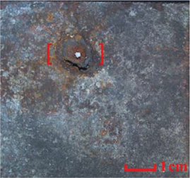
The burnt area of tuyere small sleeve.
Simulative mathematical model
The structure of the small tuyere sleeve
According to the design drawings, we simplified the structure of the coppery tuyere small sleeve. Figure 2 displays the structure and size of small sleeve of blast-furnace tuyere. Because of its axisymmetric structure, we only calculated the temperature distribution on the right side for convenience.

Structure and size of small sleeve of blast-furnace tuyere.
The heat conduction equation used in the calculating process
Due to the transfer principles in metallurgy, the heat conduction equation concerning axial symmetry can be shown as follows [7]:
In this equation,
Table 1 indicates the physical parameters of materials used when simulating the temperature field of the coppery tuyere sleeve [8].
Physical parameters of materials.
| Pure copper | 390 | 8,930 | 380.5 |
| Limescale | 0.48 | 2,700 | 860 |
Boundary condition
There are two boundary conditions in temperature field of the tuyere. One is radiation boundary condition, the heat flux density under which can be shown as:
In this equation:
The other is convective boundary condition, the heat flux density under which can be shown as:
In this equation,
In Figure 2, L1 stands for the inner wall of tuyere, which is the convective boundary condition. We set hot air temperature
Simulation results and analysis
We conducted temperature simulation of tuyere small sleeve of the blast furnace by the Fluent software. The whole process was guided by the methods provided in bibliography [10]. We studied the temperature distribution of coppery tuyere small sleeve under different conditions (without limescale, with limescale and without cooling water). Since the whole process was conducted under steady-state conditions, in eq. (1),
Figure 3 shows the temperature distribution of coppery tuyere small sleeve without limescale. From Figure 3, we can see that the temperature of the front end of the tuyere reaches the highest, while that of its backward end and outside gets down to the lowest. The former phenomenon can be explained by several factors such as thermal radiation of iron and slags, convection heat transfer of furnace gas and hot blast. While the latter one can be explained by the refrigeration of the circulating water and its low temperature environment. Under steady-state conditions, the highest temperature of the tuyere small sleeve is 360℃, the temperature distribution is well distributed. And there will not be corroded during this process.
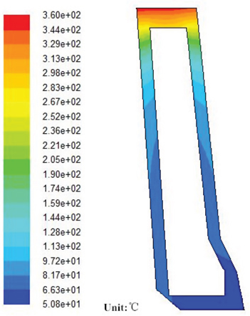
Temperature distribution of coppery tuyere small sleeve without limescale.
Generally speaking, after a long use, the inner wall of the tuyere will be covered by a layer of limescale. In Table 1, the heat conductivity coefficient is quite low. The limescale will definitely shorten the working life of the tuyere small sleeve. The temperature distribution of coppery tuyere small sleeve with limescale of different thickness is shown in Figure 4.
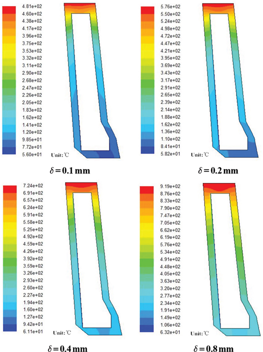
Temperature distribution of coppery tuyere small sleeve with limescale.
From Figure 4, we can see that the temperature of the tuyere small sleeve takes on upward trend when there is limescale. When the thickness of limescale is 0.1, 0.2, 0.4 and 0.8 mm, respectively, the highest temperature of the tuyere is 481°C, 576°C, 724°C and 919°C. The temperature is higher than tuyere small sleeve without limescale by 121°C, 216°C, 364°C and 559°C, respectively. Since the fusion point of the pure copper is 1,083°C. Under normal working conditions, the temperature of pure copper should not be higher than 400℃. Otherwise, its cooling intensity will decrease greatly. And the higher the temperature is, the more likely the melting loss will happen. When the temperature exceeds that of copper’s strong oxidation, or even reaches the melting point of copper, the tuyere will be burnt down. Thus, the melting loss frequency of tuyere small sleeve is directly proportional to the thickness of the limescale. We should take timely measures and improve the quality of the cooling water to limit the generation of the limestone.
Figure 5 demonstrates the temperature distribution of coppery tuyere small sleeve without cooling water. In this chart, if there is no cooling water, the highest temperature of the tuyere small sleeve can reach 1,440°C, which is much higher than the melting point of pure copper. Even the lowest temperature can be 878°C. Thus the tuyere small sleeve will be badly damaged with its work greatly affected. That will do harm to the smooth operation of the furnace.

Temperature distribution of coppery tuyere small sleeve without cooling water.
The microscopic analysis on the melting loss of the tuyere small sleeve
The damaged tuyere small sleeve specimen was crossly cut in the first step. Then scanning electron microscopy energy-dispersive spectroscopy (SEM-EDS) was conducted. The observation cover was exactly the cutting section of the melting loss spot. Figure 6 shows the section morphology when magnification is 50 times. The upper part is the cutting section near the external melting hole. And the downward part is not far from the internal melting hole. As shown, the section is divided into two strips around the melting spot.
The section morphology when magnification is 50 times.
Figure 7 indicates the morphology of the section near the internal (a) and external (b) hole. The appearance of another transition strip near the section of external hole can be found clearly in the picture.
The morphology of the section near the internal and external hole.
Figure 8 shows the energy spectrum analysis of the section near the internal hole, seeing from the selected area on the left side of the spectrum analysis in Figure 8(a), what appears on the left side of the boundary is Cu, the content of which is 100%, there is no other substance; according to the selected area on the right side of the spectrum analysis in Figure 8(b), what appears on the right side of the boundary is Fe and C, the mass percentage of Fe is 93.64% and that of C is 6.36%, no existence of Cu indicates that the hot metal in the blast furnace has leaked into the inner part of the copper around the burnt spot. The spectrum analysis results of the mark in Figure 8(c) can be seen in Table 2; we can thus infer that what left here is blast furnace slag, which shows the fact that the inner sealing section is melted with not only hot metal but also slags.
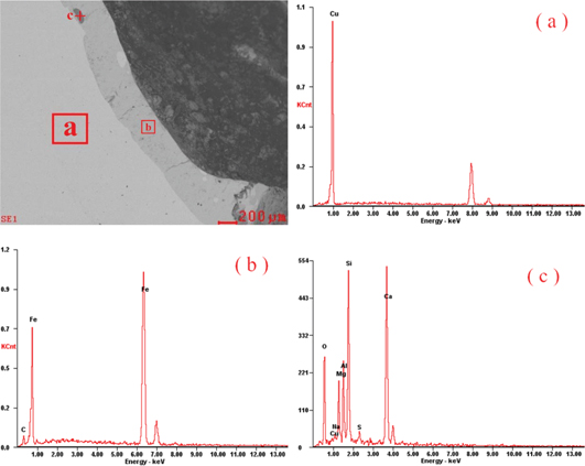
The energy spectrum analysis of the section near the internal hole.
The spectrum analysis results of the mark in Figure 8(c).
| Elements | O | Cu | Na | Mg | Al | Si | S | Ca |
| Content (mass %) | 34.1 | 1.19 | 0.69 | 6.18 | 8.20 | 20.40 | 1.53 | 27.71 |
Figure 7(b) indicates the cutting section around the external hole, a transition strip can be seen in the picture, the spectrum analysis of the light-colored strip on its left side is the same as the area on the left side in Figure 8(a), both of them are Cu. Figure 9 shows the energy spectrum analysis of the section near the external hole and its right area. In Figure 9(a), the mass percentage of Fe is 96.69%. While in Figure 9(b), the percentage is 88.84%. This shows that there is indeed a transition strip with concentration gradient near the section beside the external hole. The content of Fe here is lower than that of the right area of the transition strip.
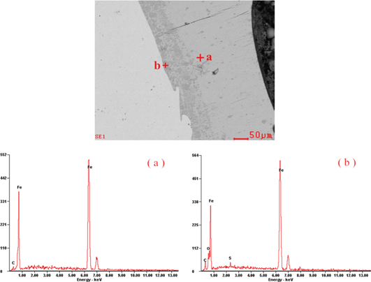
The energy spectrum analysis of the section near the external hole.
According to the analysis stated above, we know that there was Fe within copper matrix, which will closely combine with the concretionary iron liquid. In some documents [11], the concretion of iron liquid on the copper matrix is seen as the combination of clad material and base material. Generally speaking, there are two ways to combine these two materials [12]. One is melt metallurgical bonding and the other is diffusion metallurgy bonding. When the surface of clad material and base material are at the melting status, the way to combine the liquid–solid interaction and cooling crystallization can be called melt metallurgy bonding. When the clad material is melting while the base material is not, there will be liquid–solid interaction. The way that the molten clad material diffuses into the base material and the two parts mixed together is called diffusion metallurgy bonding.
Generally speaking, due to the heat transfer protection of circulating water on the copper matrix, when the iron liquid with high temperature drops on the tuyere copper matrix, the surface of it will not be melted. Thus the concretion of the iron liquid on the tuyere copper matrix is taken as diffusion metallurgy bonding only. The damaged tuyere small sleeve in this essay, however, was eroded and perforated by iron and slag. Thus there was a large amount of Fe in copper matrix, from this we can see that there was both diffusion metallurgy bonding and melt metallurgy bonding in this process. The reasons why the tuyere small sleeve was melt-through can be categorized into two aspects. One was too much limescale, and the temperature of the tuyere small sleeve rose with the limescale’s thickness. When the temperature reached the melting point of copper, the drop of liquid iron made contact with copper and they were melted together. The other was a brief interruption of the cooling water circulation caused by some particular reasons. Without cooling water, the temperature of the tuyere small sleeve increased sharply. The interaction between molten tuyere copper matrix and molten iron gave rise to the burning through of tuyere small sleeve. The copper matrix’s being molten through could tell its fusion. Therefore during the perforation process of tuyere small sleeve, melt metallurgy bonding must be happened.
Diffusion metallurgy bonding between the two kinds of materials happened under the following conditions: (1) the diffusion elements can resolve in the matrix of the other material to some extent, the more it can be resolved, the larger the diffusion extent might be; (2) the atoms should get enough energy for its diffusion; (3) the two materials might closely contact with each other at the interface. Lots of research [13–16] show that there is diffusion metallurgy bonding at the spot where combines both solid Cu and solid steel, liquid copper and solid steel. There was great concentration imbalance at the Fe/Cu interface. Atoms might get enough energy under the condition of high temperature, etc. Then the atoms of Fe and Cu might diffuse into each other, since the atomic radius of Fe is smaller than that of Cu. So the diffusion from Fe to Cu is more than that from Cu to Fe. The diffusion atoms could combine with matrix forming solid solution. The intensity of diffusion combination interface is stronger than the cutting intensity of matrix, and there is concentration gradient at surface where there is a diffusion metallurgy bonding between Fe and Cu. This illustrates for the phenomenon of Figures 8 and 9, showing there is diffusion metallurgy bonding during the melting process of tuyere small sleeve.
Conclusions
The temperature of coppery tuyere small sleeve is well distributed when there is no limescale in the lumen and the circulating water worked normally. No melting loss can be happened during this process.
The temperature of coppery tuyere small sleeve increases with the thickness of limescale. When the limescale’s thickness reaches an unacceptable level, melting loss is easy to happen.
The interruption of circulating water would increase the temperature to an extent far beyond the melting point of the copper, which does great harm to the tuyere small sleeve.
There are mainly iron and slags exist in copper matrix after the melting loss process. This indicates that the melting loss of tuyere small sleeve is caused by iron-slag erosion.
Both the melt metallurgical bonding and diffusion metallurgical combination happen in the process of burning through. There is a concentration gradient at the junction surface in the latter combination.
To avoid the melting loss of tuyere small sleeve, it is better to remove the limescale of the lumen of the tuyere, improve the water quality of the circulating water, ensure the smooth fluxion of the circulating water and develop the coating of tuyere small sleeve or replace it with other kind of materials.
Funding statement: Funding: The authors express their appreciation to the National Key Technology R&D Program of China (No. 2011BAC01B02).
References
1. LiL. On study hot and corrosion-resistant materials of tuyere small sleeve. Sci Technol Inf2010;11:94–95.Search in Google Scholar
2. DuP, HuaT, WeiHC, SeijiT. Investigation of the causes of tuyere burnout and development of its countermeasures. Corpus of the 2012 session of the national ironmaking production technology and ironmaking academic conference, vol. 2, Wuxi, 2012:192–204.Search in Google Scholar
3. SunAJ, ZhouSJ. Cr-Zr-Cu material for the tuyere small sleeve of blast furnace and its production technology. Foundry2004;53:621–2.Search in Google Scholar
4. LiL. Study of the Be-bronze small tuyere sleeve of blast-furnace with high Performance and long life. Nanchang: Nanchang University, 2011.Search in Google Scholar
5. JohnG, HaroldR. Toward an understanding of coal combustion in blast furnace tuyere injection. Fuel2005;84:1229–37.10.1016/j.fuel.2004.06.036Search in Google Scholar
6. ZhangWC. Numerical analysis for the multiphase flow of pulverized coal injection inside blast furnace tuyere. Appl Math Modell2005;29:871–84.10.1016/j.apm.2004.11.004Search in Google Scholar
7. ShenYS, LiBW, WuML. Principles of transfer in metallurgy. Beijing: Metallurgical Industry Press, 2006.Search in Google Scholar
8. TianRZ, WangZT. Copper alloy machining directory. Changsha: Central South University Press, 2002.Search in Google Scholar
9. LiYY. The designing and using on the FEM protection of tuyere. Beijing: Central Iron & Steel Research Institute, 1997.Search in Google Scholar
10. LiCX, CaoL, XuN. Preventing method for erosion of blast furnace tuyere. J Shenyang Univ Technol2008;30: 60–3.Search in Google Scholar
11. SunAJ, ZhouSJ, LiXH. Failure mechanism of small sleeve of blast-furnace tuyere and discussion of changing to use be-bronze. Hot Working Technol2009;38:81–4.Search in Google Scholar
12. XuBS. Material surface engineering. Harbin: Harbin Institute of Technology Press, 2005.Search in Google Scholar
13. WangXF, LiuDY, LiuSC. Study on diffusion technique of steel/brass bimetallic tube. Nonferrous Met Process2005;34:27–9.Search in Google Scholar
14. FangXY. Microstructrue and bonding metallurigical behavior of copper cladding steel wire by liquid and solid bonding and rolling process. Hot Working Technol2006;35:9–11.Search in Google Scholar
15. WangP, LiuSC, LiuDY. Study on diffusion interface of copper/steel. Nonferrous Met Process2006;35:34–7.Search in Google Scholar
16. WangXL, WangZB, ChenZH. The Study of diffusion of copper and carbon Steel 45. Hot Working Technol1993;4:34–6.Search in Google Scholar
©2016 by De Gruyter
This article is distributed under the terms of the Creative Commons Attribution Non-Commercial License, which permits unrestricted non-commercial use, distribution, and reproduction in any medium, provided the original work is properly cited.
Articles in the same Issue
- Frontmatter
- Research Articles
- The Effect of Aging Heat Treatment on the Microstructure and Mechanical Properties of 10Cr20Ni25Mo1.5NbN Austenitic Steel
- Weldability Characteristics of Sintered Hot-Forged AISI 4135 Steel Produced through P/M Route by Using Pulsed Current Gas Tungsten Arc Welding
- Marker Method in Studying the Defect Structure in Products of the Oxidation of Highly Disordered Substrates
- Research on the Semi-Solid Compressive Deformation Behavior of Ti-7Cu Alloy
- Numerical Prediction of the Thermodynamic Properties of Ternary Al-Ni-Pd Alloys
- Study on Control of Inclusion Compositions in Tire Cord Steel by Low Basicity Top Slag
- An Improved Arrhenius Constitutive Model and Three-Dimensional Processing Map of a Solution-Treated Ni-Based Superalloy
- Reaction between Steel-Making Slag and Carbonaceous Materials While Mixing with High Density Polyethylene
- Mechanism Research on Melting Loss of Coppery Tuyere Small Sleeve in Blast Furnace
- Research on Fracture Toughness of Flattened Brazilian Disc Specimen after High Temperature
- Plasma-Augmented Fluidized Bed Gasification of Sub-bituminous Coal in CO2–O2 Atmospheres
- Structure and Properties of the Aluminide Coatings on the Inconel 625 Superalloy
- Dynamic Transmission Performances of Alumina and Mullite Refractory Ceramics in Microwave High-Temperature Heating