High-Temperature Graphitization Failure of Primary Superheater Tube
-
D. Ghosh
 ,
S. Ray
,
S. Ray

Abstract
Failure of boiler tubes is the main cause of unit outages of the plant, which further affects the reliability, availability and safety of the unit. So failure analysis of boiler tubes is absolutely essential to predict the root cause of the failure and the steps are taken for future remedial action to prevent the failure in near future. This paper investigates the probable cause/causes of failure of the primary superheater tube in a thermal power plant boiler. Visual inspection, dimensional measurement, chemical analysis, metallographic examination and hardness measurement are conducted as the part of the investigative studies. Apart from these tests, mechanical testing and fractographic analysis are also conducted as supplements. Finally, it is concluded that the superheater tube is failed due to graphitization for prolonged exposure of the tube at higher temperature.
Introduction
The function of boiler is to produce the superheated steam which is fed on steam turbine. Pulverized coal is the common fuel used in boiler along with preheated air. The boiler consists of different critical components like economizer, water wall, super heater and reheater [1]. The bunch of superheater tubes is connected with the header. Primary superheater tube is one of the critical components for necessary superheating of the steam.
Boiler tube failure is one of the foremost causes for the unscheduled outage of the thermal power plant boiler. Different damage mechanisms like creep, fatigue, erosion and corrosion are responsible for the different pressure parts of tube failure [2]. In spite of the best effort of design engineers and material scientists, engineering components may fail in service. In some cases, failure may lead to affect the reliability, availability and safety of the equipment. This finally leads to huge financial loss in different industries. In the event of a failure, it is, therefore, essential to investigate the root cause of failure in terms of design, quality of material and fabrication procedure. The root cause of the failure of the different engineering components has been conducted to prevent the repetitive failure in near future and at the same time remedial measures are also highlighted to avoid similar failure [3–17].
Graphitization is one of the high-temperature failures, commonly encountered in fossil fuel power plant boiler. Several investigators have reported graphitization failure as microstructural degradation and also the degradation of mechanical properties in terms of strength and ductility [18–20]. The prediction of damage assessment and also the remaining life in connection with the premature failure is the key issue of the structural integrity of the critical high-temperature boiler components [21–23].
In this paper, an attempt has been made to investigate the probable cause/causes of premature failure of primary superheater tube located in the furnace zone of the boiler. The location of failure zone is shown in Figure 1.
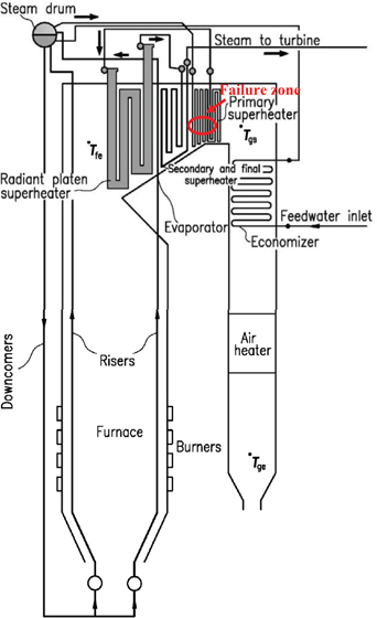
Location of failure region in thermal power plant boiler
The material specification, design and operating parameters of the tube as obtained from the plant are given as follows.
Material specification of the tube: SA-209T1 (C-1/2 Mo low alloy steel).
Working temperature and pressure of the tube: 783 K(510°C) and 98 kg/cm2.
Location of failure: Primary superheater tube.
Effective running hours: 96,000 hours (approx.).
Nominal dimension of the tube: 63.5 mm (outside diameter)×4.4 mm thickness.
Tests and results
Visual examination
Visual examination shows that the failure is wide open burst (Figure 2). No appreciable bulging is observed in and around the failure zone. The failure is taken place at the flue gas side of the tube. The maximum length of the opening is found 32 mm at the longitudinal direction and 56 mm at the transverse direction. The failure is thick lip type, indicating no appreciable thickness reduction at the edge of the fracture. No abnormal deposits are found in ID side of the tube. No significant scale buildup is also noticed at the outer surface of the tube.
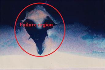
As received failed region of primary superheater tube
Dimensional measurement
The outer diameter (OD) and wall thickness are measured on the failed tube, by using digital vernier caliper and ultrasonic wall thickness gauge (type: DM-3, Krautkramer, Germany). The result (Figure 3) shows no significant changes of outside diameter and wall thick around the failure zone.
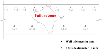
Wall thickness and outside diameter measurement of the failed tube
Chemical analysis
The failed tube is subjected to analyze chemically by spectrometer (Model: Q4 TASMAN, Bruker, Germany). The estimated chemical composition (Table 1) shows that the failed tube confirms the specification SA 210 grade A1 steel.
Chemical composition of failed tube
| C | Mn | Si | S | P | Fe |
| 0.25 | 0.90 | 0.20 | 0.008 | 0.007 | Balance |
Metallographic examination
The samples are sectioned and mounted for preparations of the sample for metallographic examination. All the samples are polished in 120, 220, 400, 600 and 800 grade SIC paper followed by diamond polishing up to 1 µm and finally etched with 2% nital. The microstructure at the failed region at unetched condition shows the presence of randomly distributed nodular graphite in the unetched matrix (Figure 4(a)). The microstructure at etched conditions reveal complete breakdown of pearlite, which finally results in nucleation and growth of graphite nodules in ferrite matrix (Figure 4(b)). The microstructure away from the failure also shows the complete breakdown of pearlite in association with initiation and growth of graphite nodules (Figure 4(c)).
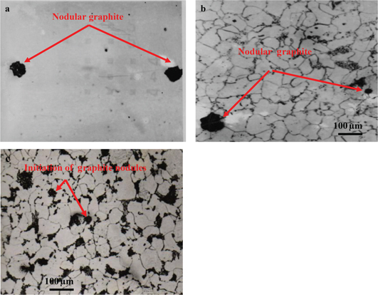
Microstructure showing (a) graphite nodules at unetched matrix at failure region; (b) complete breakdown of pearlite resulting in growth of graphite nodules at etched condition at failure region and (c) breakdown of pearlite and initiation and growth of graphite nodules at away from the failure zone
Hardness measurement
Hardness survey is conducted in and around the failure region of the failed primary superheater tube. The hardness results show decrease in hardness (124–128 HV) in the failure region in comparison to the normal value (155–160 HV) of this steel.
Fractographic analysis
The fracture edge of the failure is sectioned carefully and cleaned with acetone by ultrasonic cleaner. The cleaned fracture surface is examined in scanning electron microscope (Model – S-3000N, Make- Hitachi limited, Japan) for fractographic analysis. The fractograph (Figure 5) shows the evidence of brittle fracture. This clearly indicates the embrittlement of the fracture edge due to escaping steam immediately after failure.
Fractographic examination of failed primary superheater tube
Mechanical property analysis
The tensile samples are prepared from the unfailed tube adjacent to the failure. The tensile test specimens are tested in universal testing machine (Instron Wolpert, UK). The stress–strain plot is incorporated in Figure 6 and Table 2. The results of ultimate tensile strength (UTS) and elongation in failed tube show significant decrease in UTS (380 MPa) and also increase in ductility(30%) as compared to the normal value of SA 209T1 grade steel.
Stress–strain plot for the tensile specimen taken from the failure zone
Mechanical testing results of failed primary superheater tube
| Identification | UTS (MPa) | Elongation (%) |
| Sample 1 | 172 | 43.2 |
| Sample 2 | 157 | 42.1 |
Discussion
The visual photograph of the failure is wide open burst (Figure 2). The failure is associated with no significant bulging and wall thickness reduction (Figure 3). The chemical composition does not confirm to the desired specification (i.e. ASME SA 209T1 grade) of the primary superheater tube in this region. The microstructure at the region of failure at unetched conditions confirms the presence of nodular graphite randomly distributed to the unetched matrix (Figure 4(a)). The microstructure at etched condition at same location shows the complete breakdown of pearlite into ferrite and free nodular graphite. The graphite is randomly distributed in the ferrite matrix (Figure 4(b)). The microstructure away from the failure zone confirms to the presence of decomposed pearlite and initiation of graphite nodules mostly within pearlite colonies (Figure 4(c)). Few graphite are grown in size within the ferrite matrix. The hardness survey shows the reduction of hardness around the failure zone in comparison to the normal hardness value. The mechanical properties (Table 2) also show the significant reduction in UTS and also increase in ductility in this type of steel. The undesired value of strength, ductility and hardness can be attributed to the formation of graphite from decomposed pearlite due to prolonged exposure to the high temperature.
Graphitization may be defined in general as the formation of free graphite through the transformation of metastable metallic carbides. The most common process of graphitization involves the decomposition of the pearlite (iron + iron carbide) by transformation of the iron carbide, Fe3C (cementite) at elevated temperature to iron and graphite. Graphite formation in C, C–Si and C–Mo steel during the elevated temperature service occurs mainly as a result of transformation of the metastable cementite into iron and graphite as given below.
The process details however include both graphite nucleation and a subsequent growth place. Graphite nucleation is primarily driven by the availability of the appropriate nucleation sites while the graphite growth kinetics are generally controlled by the diffusion/transport of the slowest moving species, resulting in free carbon at the nucleated, existing graphite phase.
The observed graphitization is attributed to the use of plain carbon steel (SA 210 grade A1) instead of designed specified material (SA 209 T grade) in that particular zone for long period of time. The permitted tube metal temperature of this grade of steel is 727 K (454°C) [24], which is much lower than operating temperature 783 K (510°C). The higher temperature at this region for extended period of time leads to premature failure of the tube. The fractographic analysis of the fracture edge shows the evidence of brittle fracture (Figure 6). The escaping steam during failure causes quenching effect and leads to brittle failure.
Conclusions and recommendations
Based on the results and discussion, it is concluded that the primary superheater tube is mainly failed due to graphitization effect. The graphitization causes degradation of microstructure, which finally reduces the strength and hardness and increases the ductility of the material. The undesired strength, ductility and hardness cause premature failure of the tube.
As a recommendation, all the plain carbon tubes (SA 210 grade A1) used in this region may be replaced by higher grade C-0.5 Mo steel (SA 209 gradeT1) to avoid the similar kind of failure in this region. At the same time the temperature mapping in this region is also suggested to measure the exact temperature profile in this region.
References
1. SlaughterGM. Failure analysis and prevention. In: BoyerHE, editor. Failures of boilers and related steam power-plant equipment, metals handbook, 8th ed, vol. 10. Metals Park, OH: American Society for Metals, 1975:533.Search in Google Scholar
2. LampingGA, ArrowwoodRH.Manual for investigation and correction of boiler tube failures. Report CS 3945. Palo Alto, CA: Electric Power Research Institute, 1985.Search in Google Scholar
3. DasG, ChowdhurySG, RayAK, DasS, BhattacharayaDK. Eng Fail Anal2002;9:563–70.10.1016/S1350-6307(01)00040-1Search in Google Scholar
4. GhoshD, RoyH, ShuklaAK. Investigation of probable cause of a premature cracking of down comer nozzle of Heat recovery steam generator (HRSG). J Fail Anal Prev2009;9:517–21.10.1007/s11668-009-9297-zSearch in Google Scholar
5. GhoshD, RoyH, RayS, ShuklaAK. High temperature Corrosion failure of a secondary Superheater tube in Thermal Power Plant Boiler. High Temp Mater Proc2011;28:109–14.10.1515/HTMP.2009.28.1-2.109Search in Google Scholar
6. RoyH, GhoshD, PankajAC, ShuklaAK, BasuJ. A Case Study on the Premature Failure of a Cooling Water Pump Shaft. Int J Manuf Sci Prod2011;9:99–106.10.1515/IJMSP.2008.9.1-2.99Search in Google Scholar
7. SwaminathanJ, GugulothK, GunjanM, RoyPK, GhoshRN. Eng Fail Anal2008;15:311–16.10.1016/j.engfailanal.2007.02.004Search in Google Scholar
8. RoyH, SahaA, GhoshD, RoyS, ShuklaAK. Failure analysis of a new turbine parting plane studs. J Mech Behav Mater2011;19:373–82.10.1515/JMBM.2009.19.6.373Search in Google Scholar
9. GhoshD, RayS, RoyH. Failure investigation of High Temperature Stud. J Fail Anal Prev2014;14:17–20.10.1007/s11668-013-9769-zSearch in Google Scholar
10. ChowdhurySG, KumarP, DasSK, BhattacharyyaDK, ParidaN. Eng Fail Anal2001;8:521–8.10.1016/S1350-6307(00)00019-4Search in Google Scholar
11. GhoshD, RayS, RoyH, ShuklaAK. Investigation into cause of High Temperature Failure of Boiler Superheater Tube. High Temp Mater Proc. doi:10.1515/htmp-2014-0018Search in Google Scholar
12. GhoshD, RoyH, MondalA. Failure Investigation of condensate pump shaft. J Fail Anal Prev2014;14:450–3.10.1007/s11668-014-9845-zSearch in Google Scholar
13. MuhannadW, DeenKM. J Fail Anal Prev2010;10:161–6.10.1007/s11668-010-9332-0Search in Google Scholar
14. MondalA, RoyH, GhoshD, ShuklaAK. J Fail Anal Prev. doi:10.1007/S11668-014-9855-xSearch in Google Scholar
15. LanchaAM, SerranoM, Gomez BricaneD. Eng Fail Anal2001;8:271–91.10.1016/S1350-6307(00)00005-4Search in Google Scholar
16. RoyH, SharmaP, GhoshD, ShuklaAK. Corrosion Failure of in-service economizer tube. J Fail Anal Prev. doi:10.1007/s11668-014-9848-9Search in Google Scholar
17. GhoshD, RayS, MondalA, RoyH. Failure investigation of Radiant Platen Superheater Tube of Thermal Power Plant Boiler. High Temp Mater Proc. doi:10.1515/htmp-2013-0128Search in Google Scholar
18. EmersonRW. Trans ASME1994;66:5–15.Search in Google Scholar
19. ConantWG, ReichWA.Graphitization studies of materials for high-temperature service in steam plants. In: Paper presented at inspection and maintenance program, The ASME Annual Meeting, New York, NY, 1946.Search in Google Scholar
20. WilsonJG. Graphitization of steel in petroleum refining equipment and the effect of graphitization of steel on stress-rupture properties. Welding Research Council Bulletin No. 32. New York, NY: Welding Research Council, 1957.Search in Google Scholar
21. ViswanathanR, FouldsJR, RobertsDI.Proceedings of International Conference on life assessment and extension, Paper No. 1.6.2. Hague, June 1998:168.Search in Google Scholar
22. NarayananTV, SamuelsLE. Optical microscopy of carbon steels. Book No. H00486 ASM. Metals et al. New York, NY: ASME, 1989:223–30.Search in Google Scholar
23. FouldsJR, JewettCW, BisbeeLH, GabelTL, ViswanathanR. Proceedings of 1992 international joint power generation conference on ASME, PWR steam turbine-generator developments for the power generation industry, vol. 18, WGSteltz, ed. Book No. G00688. New York, NY: ASME, 1992.Search in Google Scholar
24. ViswanathanR. Damage mechanism and life assessment of high temperature components. Metals Park, OH: ASM Publication, 1989.Search in Google Scholar
©2015 by De Gruyter
This article is distributed under the terms of the Creative Commons Attribution Non-Commercial License, which permits unrestricted non-commercial use, distribution, and reproduction in any medium, provided the original work is properly cited.
Articles in the same Issue
- Frontmatter
- Effects of Yttrium Addition on Microstructure and Mechanical Properties of AZ80–2Sn Magnesium Alloys
- Direct Reduction of Ferrous Oxides to form an Iron-Rich Alternative Charge Material
- Investigation of BaCO3 Powders Synthesized by Microwave Homogeneous Precipitation
- Research on the Influence of Technological Forging Parameters on the Quality of Biphasic Titanium Alloys
- High-Temperature Graphitization Failure of Primary Superheater Tube
- Metal Loss of Steam-Oxidized Alloys after Exposures at 675°C and 725°C for 500 Hours
- CVD Diamond Coating on Al-Interlayered FeCoNi Alloy Substrate: An Interfacial Study
- Kinetics Study on Reduction of CaWO4 by Si from 1423 K to 1523 K
- Effect of Boron and Titanium Addition on the Hot Ductility of Low-Carbon Nb-Containing Steel
- The Effects of Carbon Content on the Microstructure and 650°C Tensile Properties of Incoloy 901 Superalloy
- Ball Indentation Studies on the Effect of Nitrogen on the Tensile Properties of 316LN SS
- Effect of Ga Addition on Morphology and Recovery of Primary Si During Al–Si Alloy Solidification Refining
- Preparation and Thermal Properties of High-Purified Molten Nitrate Salt Materials with Heat Transfer and Storage