Dual band beam steering antenna using branch line coupler network for higher band applications
-
Amit Abhishek
 und
Priyadarshi Suraj
und
Priyadarshi Suraj

Abstract
A beam-steering fed array antenna has been proposed for radar and mm-Wave applications operating from 22.6 to 26.89 GHz and 30–45 GHz with B.W % of 17.34 % and 40 % respectively having size of 12.11 × 25.58 × 0.8 mm3 (0.96λo × 2.01λo × 0.06λo). For radar, this antenna covers 24.15 GHz as police radar, 24.25–25.25 GHz & 31.8–33.4 GHz as navigation radar, and 33.4–36 GHz as high-resolution radar for airport surveillance. This antenna also covers mm-wave bands for different countries (Brazil-40 GHz, China- 34–42.5 GHz, Mexico- 33 GHz and 37 GHz, and USA- 24 GHz, 37 & 39 GHz). At initial stage, a monopole antenna with DGS has been designed with an operating band of 20.2–31.2 GHz and 36.6–42.2 GHz. Proposed antenna shifts the beam pattern at 90° with each other after exciting each port in alternative order with a scanning angle of ±45°, ±75° & ±180°. Peak gain for 1st band ranges from 7.1 to 9 dBi and for the 2nd band ranges from 8.8 to 10.2 dBi and has a radiation efficiency of 88 %. Other diversity parameters such as ECC, DG, MEG, and isolation get analysed to observe the coupling effects. Design, development, and analysis of all antenna parameters is done by using HFSS 19 platform.
1 Introduction
Beam-steering antennas are used to mitigate the interferences in multipath environments with good radiation at a certain angle. The uniform distribution of radiated power in a particular direction helps antenna to transmit and receive any information with enhanced throughput in a given channel. Without any mechanical movement based on the phase array principle steering of beam electronically using a switching mechanism is another method for beam-steering [1]. A 2 × 2 array fed microstrip patch antenna with an enhanced gain is proposed by some researchers with a maximum scanning angle of ±17° applicable for 5G communication. In this antenna, author uses a microstrip slot branch circuit of 100 Ω impedance as a power divider at the ground side. At the top side quad rectangular patch is used with connecting arms of 50 Ω impedance [2]. For a millimetre wave (28 GHz) applications few authors have used concept of connected fed array antenna via integrated slot structure. They use single-slot and double-slot connected array antenna with a gain of 9.89 dBi and 12.5 dBi respectively [3], [4]. For satcom applications, an SIW (substrate-integrated waveguide) technique is used by some authors. They use a concept of SGG (substrate-guided ground) which helps antenna to cover a wide scanning angle and good gain. For a massive MIMO antenna, a steerable multiple beam pattern-based antenna as a reconfigurable reflect array is also used [5], [6]. For beam-steering power travels through antenna should be equally divided at output ports. To switch active input ports CMOS-based switches with efficient power are used by some authors for both lower and higher band applications [7]. For adjusting amplitude & phase of beam, antenna on chip array-based configuration with different modes of phase shifter. It allows the expansion of scanning ranges with narrower beams and high data rates [8], [9]. A meta-surface four-layered stack antenna with five different beam steering angles is used as a single unit for satellite communication by some authors [10]. A coupled cascaded transmission line and isolated network leads to transformation of impedance value. Due to this transformation power distribution network provides a narrow beam with good isolation measured at output ports [10], [11]. Generalized joined couplers, and based on Hadamard matric theory concept couplers with switching mechanisms are also designed by different authors for lower band applications [9], [12], [13]. With a compact slot meandering a single antenna gets fed as miniaturized arrangement with eight ports as circularly polarized beam-steering antenna suitable for diversity scheme [14]. A circularly polarized butler matrix based on a Febry-Perot resonator having integration of SIW leads to narrow beam width. Beam-width gets reconfigured after switching to loaded parasitic ring which is applicable for satellite services [15], [16]. Phase reconfigurability is done by calibration of RF input signal, a self-calibration RF circuit has been proposed by some authors to help antenna steer itself at respective angles [17]. After combination of branch line coupler and crossover gets transformed into a compact and reconfigurable beam forming/steering network. For an ultra-wide scanning angle, a 1 × 8 phased array antenna with half-loop topology has been designed by some authors [18], [19], [20], [21]. A beam-steering antenna for radar and mm-wave applications has been designed using a branch line coupler (BLC) and a monopole antenna using Rogers-RT Duroid 5,880 (Ꜫr = 2.2 & dissipation factor of 0.0009). Formation of beam-steering antenna is a combination of BLC network with fed monopole antenna at load. A monopole antenna is designed using DGS technique and its design steps/flow with complete responses is discussed in Section 1. Another Section 2 shows analysis and design of branch line coupler with transition of lower to higher operating bands. Section 3 shows analysis of beam-steering antenna after excitation of both ports one and two simultaneously and independently. In this article some important results of antenna diversity parameters are discussed with beam-steering mechanism at wide scanning angle for respective operating frequencies.
2 Development of monopole antenna
For a beam-steering antenna, development of an elementary antenna is required to fed at respective ports of BLC network. A compact horn structured monopole antenna using DGS having size of 5 × 5 × 0.8 mm3 has been proposed as the fed antenna. To maintain miniaturization, DGS plays a vital role in designing this antenna. Figure 1. Shows the designing steps with the proposed antenna’s structure. Fed line of 50 Ω impedance is used having a width of 1.8 mm and length of 1.6 mm and these parameters are calculated at an operating frequency of 40 GHz. In step 1 a T-shaped patch structure is used with full ground as a microstrip patch antenna having the size of 5 × 5 × 0.8 mm3. It is operating at 52 GHz and beyond but it does not cover the desirable bands. In step 2, T shaped patch gets converted into a horn structure operating at same band with an improved reflection coefficient (|S11|). In next step, a rectangular slot of 0.2 mm is formed before the horn structure and its behaviour seems to be same as horn structure antenna. Then a monopole or partial ground structure is used in step 4 where dual band is achieved where, 1st band operating at 20 GHz and 2nd band at 60 GHz with unsatisfied return loss. In the next step 5, a uniform stair type structure is used as DGS but its response seems to be same as last designed antenna. A half-circular ring of width 0.5 mm gets added to the stair-based structure to enhance the technique of DGS to reach the desirable operating band. Keeping the patch same as in step 3 and enhancing the technique of DGS leads to final proposed antenna. This antenna covers a dual band with cut-in frequency (Fc) of 24.4 GHz and 39.8 GHz with reflection coefficients of −23 dB and −16 dB respectively. B.W % of 42 % and 14.2 % are observed at both respective bands (20.2–31.2 GHz; 36.6–42.2 GHz). The responses of reflection coefficient (|S11) at operating frequencies for all designing steps including the proposed antenna are shown in Figure 2. VSWR (voltage standing wave ratio) versus frequency response is shown in Figure 3a. covers the of VSWR in between one and two for both operating bands. The desirable range of VSWR should be under two considered as good match for any antenna applications. The plot of |S11| gets integrated with VSWR plot at respective bands for better comparison as shown in Figure 3a. Although directivity & antenna gain are closely related, antenna gain also considered as antenna’s efficiency. The ratio of the intensity in a particular direction and the radiation intensity, that would be obtained if the power accepted by antenna were radiated isotopically is termed as gain. Antenna gain ranges from 3.2 to 4 dBi and 4.8–4.2 dBi having a maximum gain of 4.8 dBi with an average radiation efficiency of 95 % for both operating bands. This efficiency shows the relation between the maximum power radiated by an antenna with power fed at excited port. The response of these parameters is shown in Figure 3b. The behaviour of conducting element/radiator depends on radio frequencies and due to dissipation factor of any substrate there is a phase shift in radio signals. Due to this, there is a rate of change in the transmission signal with some phase shift termed as group delay (GD). The response of GD at a respective band with |S11| response is shown in Figure 4a. At maximum return loss, there is a peak in the group delay response for both bands. At 0 dB GD is 40 ps (pico-second), at −24 dB GD 170 ps and at −15 dB GD is 170 ps, which clearly shows the dependent relationship between the group delay and reflection coefficient.
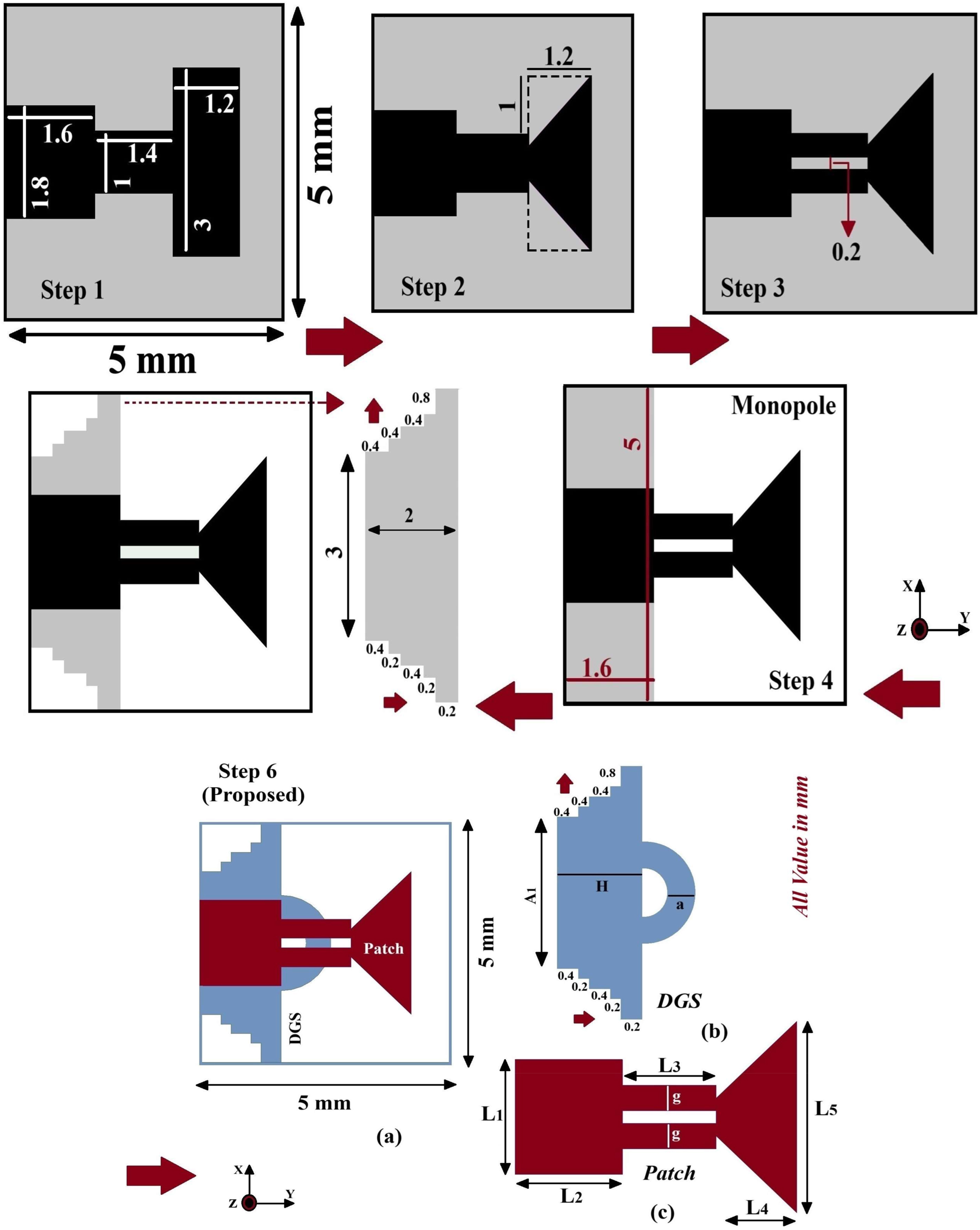
Design flow of proposed antenna at different designing steps with its parametric values. Proposed antenna (a) monopole antenna prototype (b) DGS structure with A1 = 3 mm, H = 2 mm, a = 0.5 mm (c) patch structure with L1 = 1.8 mm, L2 = 1.6 mm, L3 = 1.4 mm, L4 = 1.2 mm, L5 = 3 mm and g = 0.4 mm.
![Figure 2:
Responses of S-parameter [S11] versus frequency of each designing steps and final proposed antenna.](/document/doi/10.1515/freq-2024-0078/asset/graphic/j_freq-2024-0078_fig_002.jpg)
Responses of S-parameter [S11] versus frequency of each designing steps and final proposed antenna.
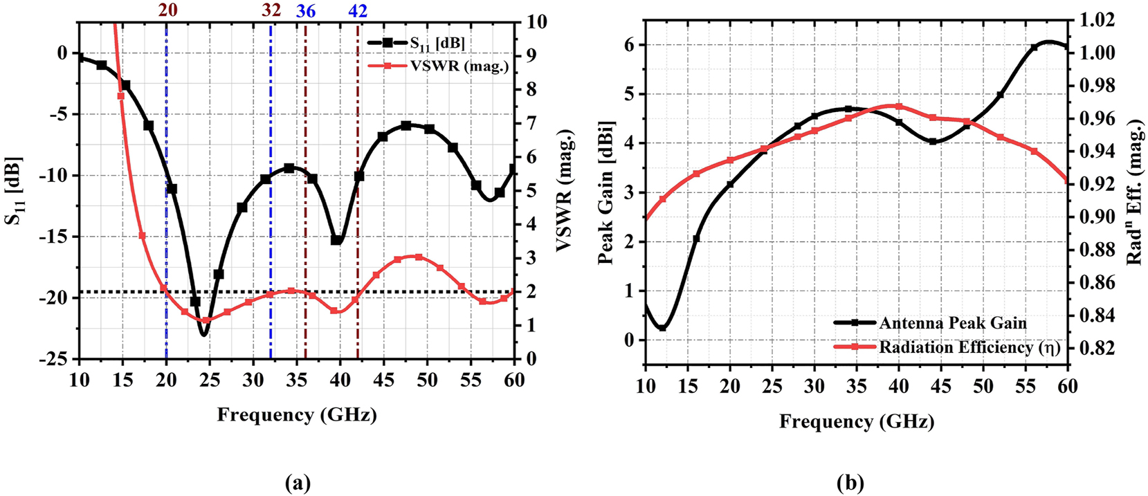
(a) Response of VSWR with S11 at resonating frequency (b) peak gain and radiation efficiency plot of monopole antenna.
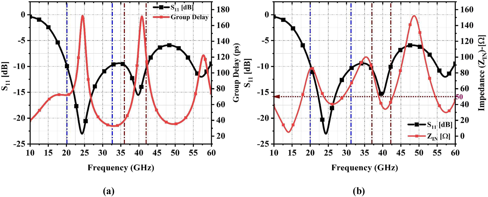
(a) Response of group delay and S11 for monopole antenna (b) impedance response with S11 at respective operating frequencies.
An input impedance of 50 Ω is used for calculating the dimension of width and length of fed transmission line connected to the conducting element. At this impedance value power gets excited as input and maximum amount of power gets reflected back as a return loss/reflection coefficient. At maximum return loss impedance value should be approximately to 50 Ω for better matching and efficiency of antenna. The observed value of impedance ranges between 40 and 70 Ω at both bands as shown in Figure 4b. Figure 5 shows the radiation pattern at E-plane and H-plane with co and cross (X) polarization. Co-polarized pattern is observed when the transmitting and receiving antenna is in same direction or in same plane while a cross-polarized pattern occurs when both transmitting and receiving antenna is perpendicular to each other.
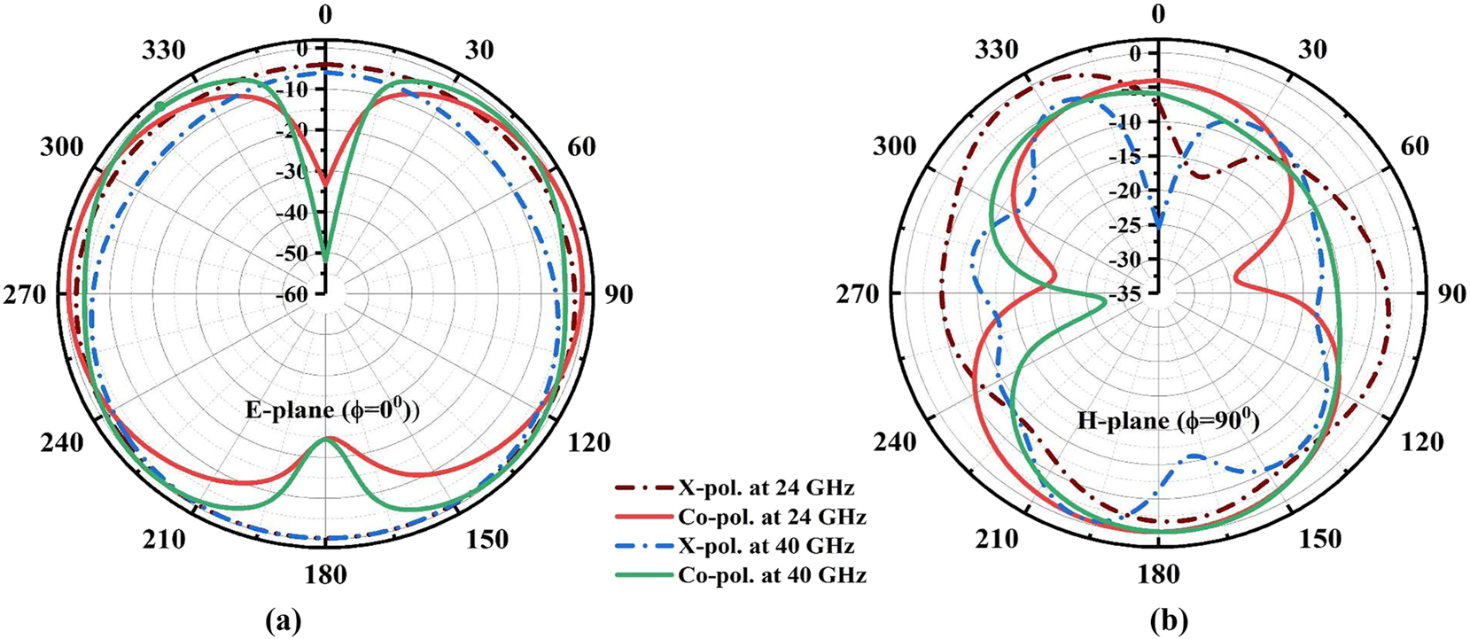
Radiation pattern (a) E-plane (phi = 0°) (b) H-plane (phi = 90°) of proposed monopole antenna.
The electric field plane & magnetic field plane should be perpendicular to each other as phi = 0° and phi = 90° respectively. For this monopole antenna the level of cross-polarization is circularly polarized. The maximum amount of a current is distributed over the conducting surface of monopole antenna is also measured as an electric field (V/m) at respective operating frequencies. The maximum amount of electric field at 24 GHz and 40 GHz is 15000.91 V/m and 20569 V/m respectively as shown in Figure 6a and b.
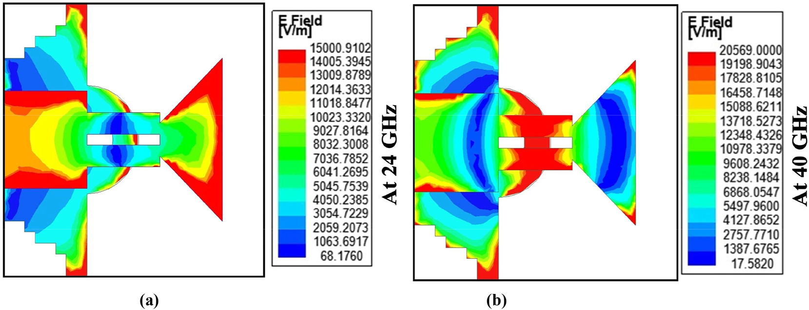
Electric field plot (a) at 24 GHz (b) 40 GHz.
3 Design of 90° hybrid branch line coupler
Before approaching to beam-steering network, a four-port directional coupler is designed with a size of 12.11 × 13.39 × 0.8 mm3 (0.96λ0 × 1.07λ0 × 0.06λ0). All four ports are matched with Z0 characteristics impedance and it behaves as a transmission line to establish a connection between each port via
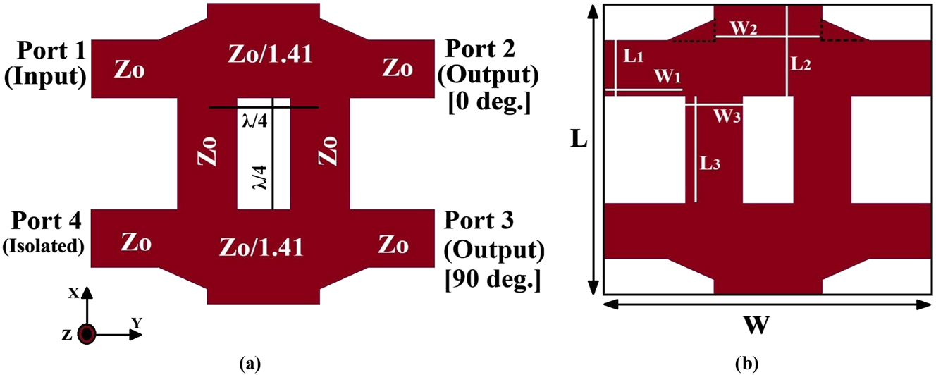
Branch line coupler design (a) with impedance parameter (Zo = 50 Ω) (b) with parametric value as L = 12.11 mm, L1 = 2.34 mm, L2 = 3.81 mm, L3 = 4.49 mm, W = 13.39 mm, W1 = 4.49 mm, W2 = 4.41 mm and W3 = 2.34 mm.
![Figure 8:
S-parameter response of BLC (a) at 10 GHz [lower operating frequency] (b) at 24 GHz [higher operating frequency].](/document/doi/10.1515/freq-2024-0078/asset/graphic/j_freq-2024-0078_fig_008.jpg)
S-parameter response of BLC (a) at 10 GHz [lower operating frequency] (b) at 24 GHz [higher operating frequency].
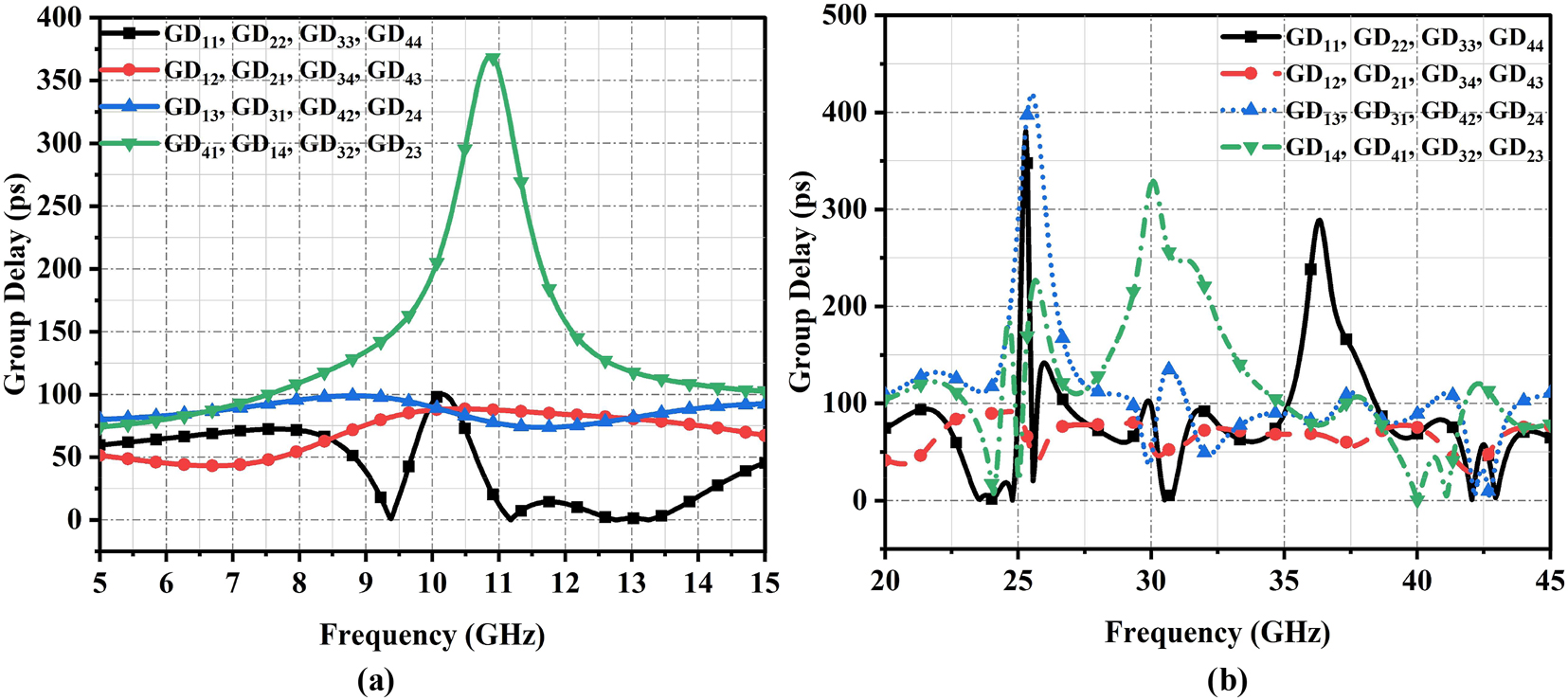
Group delay responses at each port for (a) 10 GHz BLC (b) 24 GHz BLC.
The proposed BLC gets transformed into a dual BLC network as shown in Figure 10 having size of 12.11 × 22.29 × 0.8 mm3. This BLC network covers a bandwidth of 22.4–26.7 GHz and 29.8–45 GHz with B.W % of 17.55 % and 40.6 % respectively at each excited port (S11, S22, S33 & S44). The simulated response of S-parameters for all the ports is shown in Figure 10. The reflection coefficient for 1st and 2nd bands is ≤−10 dB respectively.
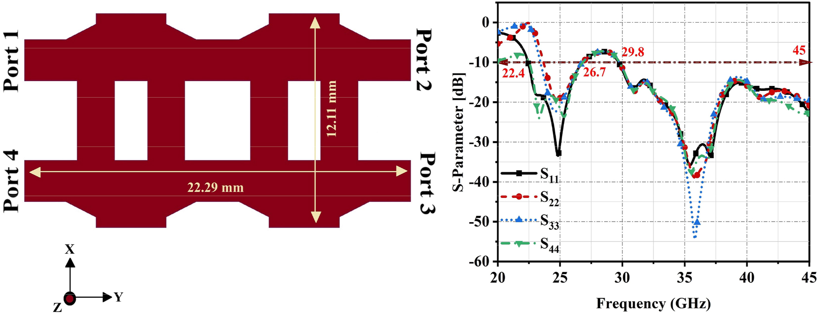
Transformed BLC network with reflection coefficient response at each excited port.
4 Beam steering network fed array antenna
The monopole antenna using DGS technique gets fed at port 2 and port 3 of the dual BLC network is termed as a beam-steering antenna. The prototype view of proposed beam-steering antenna with its dimension and port allocation is shown in Figure 11(a) as top and bottom view, similarly the fabricated antenna is also represented in Figure 11(b). For verifying multiple antenna characteristics an analysis has done by exciting each port simultaneously. The return loss at desirable operating frequency with wide bandwidth shows a better match for any antenna. The simulated and measured reflection coefficient plot at operating frequencies is shown in Figure 12(a). The simulated |S11| & |S22| ≤−10 dB for both band by covering B.W of 22.4–26.9 GHz and 29–45 GHz respectively. The measured reflection coefficient at port 1 and port 2 is very close to the simulated value. It is observed that second operating band shows maximum simulated |S11| of −52 dB and measured of −40 dB at port 1 & 2 respectively. Similarly, simulated & measured |S11| of −25 dB and 28 dB for the first band. The simulated isolation or insertion loss in between the adjacent identical fed antenna as |S12| and |S21| is greater than 22 dB for 1st band and 25 dB for another band. The measured isolation is greater than 15 dB and 20 dB respectively for both bands is found. The response plot for the same is shown in Figure 12(b).
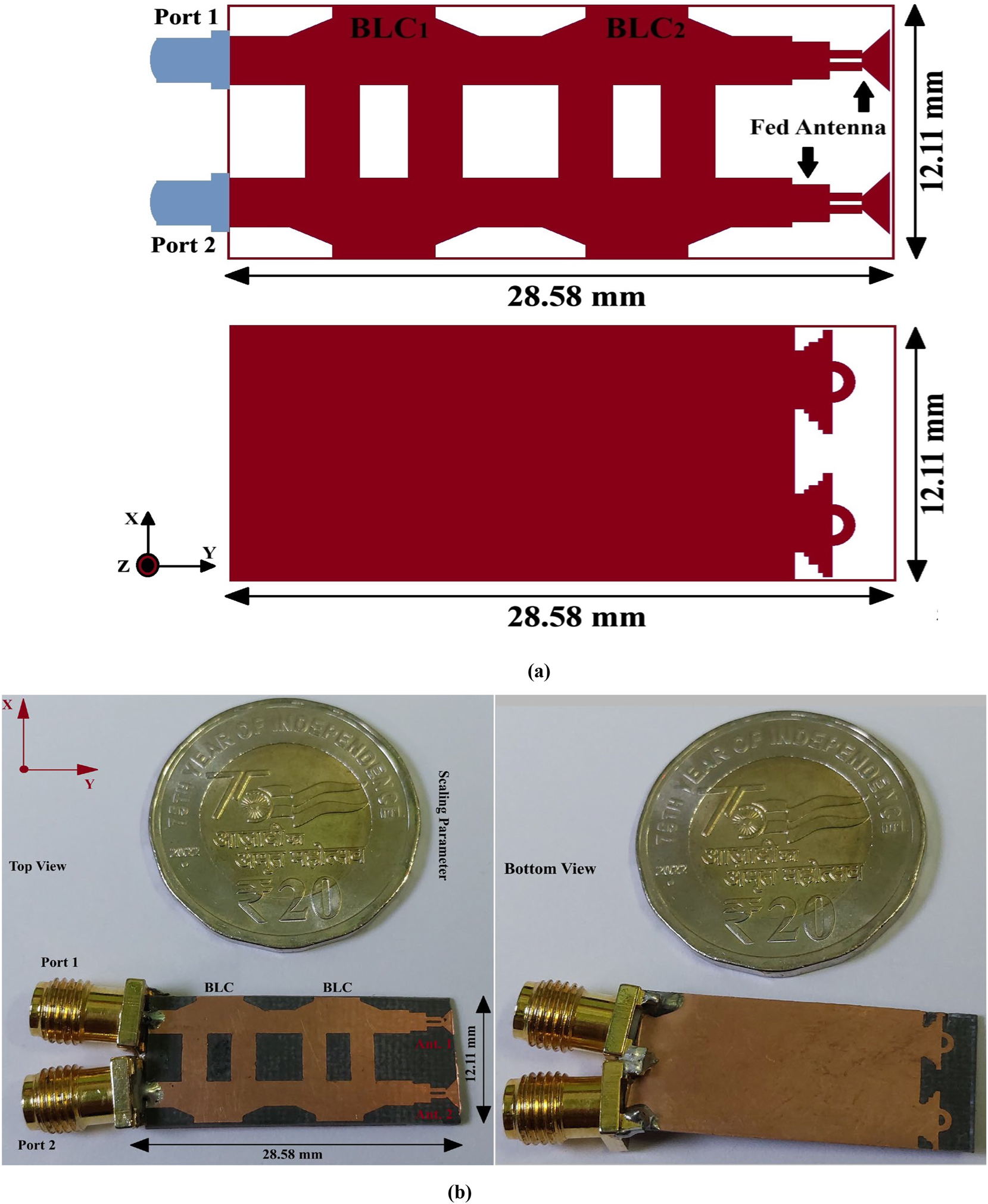
Beam steering antenna as top and bottom view (a) prototype view (b) fabricated/hardware view.

Simulated and measured response of (a) reflection coefficient (b) isolation between adjacent fed antenna.
The decoupling between each antenna with a good match is observed and envelope correlation coefficient (ECC) is affected by mutual coupling. If the value of ECC is close to zero then coupling will be very low. Using scattering parameter characteristics value of ECC is calculated using equation (1). For two adjacent antenna elements, SXX is identified as |S11|, SXY as S12, SYX as S21, and SYY as S22 used in equation (1). The simulated ECC is very close to zero and the measured ECC is 0.025. Based on ECC diversity gain (DG) is also measured using equation (2). This antenna also behaves as a MIMO antenna and its diversity parameters get affected in terms of signal-to-interference ratio. Due to dual antenna at
the fed port, the radiation from each element leads to interreferences and it will affect the overall performance of the antenna. Diversity gain shows the amount of power that gets reduced in any diverse environment without decaying the antenna performances. For a better match, DG should be 10 and this antenna shows the simulated value of 9.88 and measured as 9.255. The response of ECC and DG as measured and simulated is shown in Figure 13(a). The mean effective gain (MEG) shows that in multiple path surroundings, the amount of power gets received by an antenna. Basically, it is a ratio of received power to incident power and it is calculated using equation (3). MEG at ports 1 and 2 for two radiating elements is calculated using equations (3a) and (3b) respectively and resultant MEG is found using equation (3c). For better performance of antenna in a multipath fading MEG should be less than −3 dB. For this antenna resultant MEG is reported at 0 dB having MEG1 & MEG2 ≤ −5 dB. The response plot of MEG is shown in Figure 13(b).
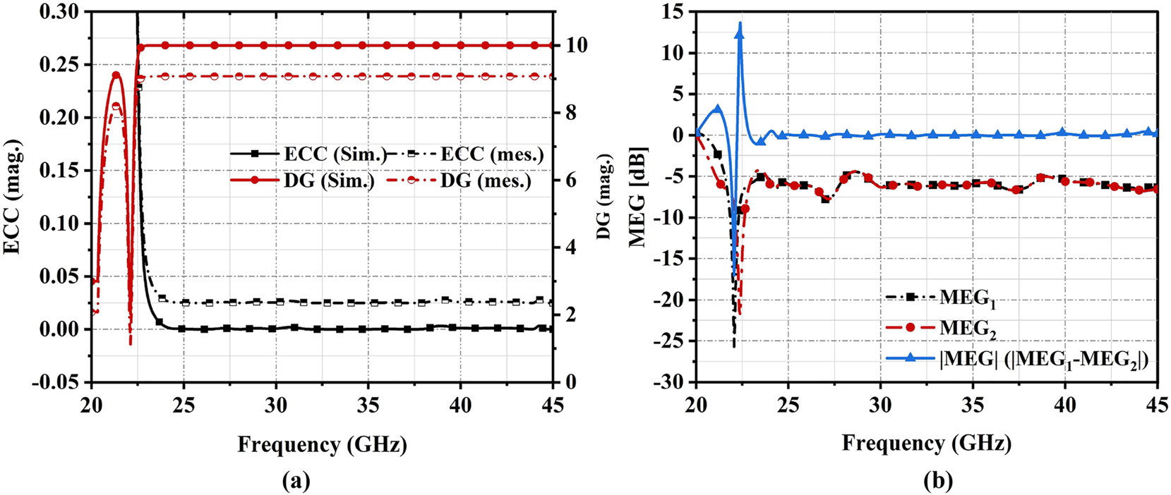
(a) Simulated and measured response of ECC and DG (b) response plot of MEG.
After analysis of decoupling characteristics for two adjacent antenna in a multipath environment this antenna is used to steer the beam pattern with phase shift of 90°. The simulated and measured response of reflection coefficient after exciting each port independently (in alternate mode) is shown in Figure 14(a) covering dual bands. The reflection coefficient ≤−10 dB at port 1 and port 2 for both measured and simulated. The maximum return loss is −50 dB at 24 GHz, −42 dB at 33 GHz, and −35 dB at 39 GHz respectively as shown in Figure 14(a) by covering the required bandwidth for Radar and mm-Wave applications with B.W % of 17.40 % and 40 % respectively. Antenna gets tested via Vector Network Analyzer (VNA) and the measured response at excited port is shown in Figure 15. The antenna testing set up in an anechoic chamber is also presented in Figure 15. Measured and simulated response of VSWR is observed with very slight variations in responses for both excited ports as shown in Figure 14(b). For 1st band, the values of VSWR lies in between one and 2 & for 2nd band it lies in between one and 1.5. Simulated antenna peak gain of 9 & 9.5 dBi for both band 1 and 2 respectively at port 1. The measured peak gain at port 1 is 8.3 and 8.5 dBi. At port two peak gains of seven dBi & 7.2 dBi are observed as simulated values for both bands, while the measured peak gain of 6.8 dBi and 7.5 dBi is found.
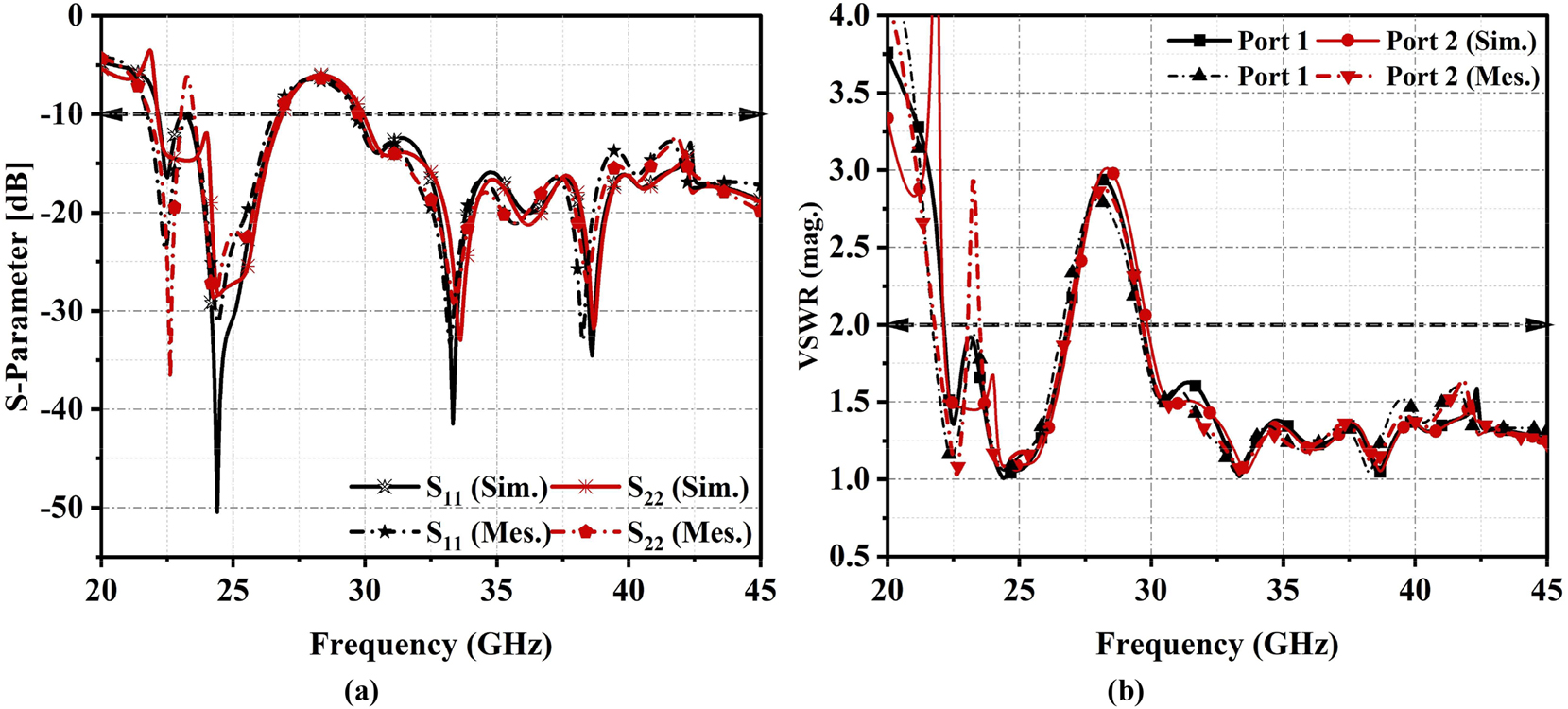
Measured and simulated (a) return loss response (b) VSWR plot.
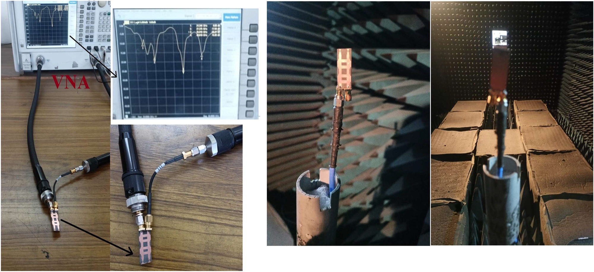
Antenna measuring set up with VNA and in anechoic chamber.
Radiation efficiency for both bands is reported in between 83 and 89 % as simulated and 81–86 % as measured. The response plot of peak gain and radiation efficiency is shown in Figure 16(a). Maximum group delay response is shown in nano second (ns) at respective operating frequencies where, maximum return loss is observed. The response of group delay is shown in Figure 16(b). Beam-steering mechanism is analysed by switching each port alternatively at respective resonating frequencies. At 24 GHz the radiation pattern or beam is directed towards the +45° and −75° when port 1 gets excited and if port 2 gets excited the similar beam gets steered by 90° at −45° and +75° respectively. Similarly, at 33 GHz beam pattern gets steered by 90° shifts after exciting each port independently, with scanning angles of ±45° and 180°. At 36 GHz pattern is uniformly directed towards −45° angle and gets steered after switching to port 2 by +45°. Scanning angles at 39 GHz are ±15° and 45° respectively with the same radiation intensity is found. A directional beam gets shifted by 90° at 42 GHz with a scanning angle of ±10°. The simulated and measured beam-steered pattern at the respective frequencies for port 1 and port 2 is shown in Figure 17. Through the conducting surface of the beam-steering antenna distribution of current in V/m is shown in Figure 18 when port 1 is active. The maximum current travels from port 1 and it gets distributed equally to both fed antenna as an array. Port 2 receives a very small amount of current and behaves as an isolated port. The same mechanism will work when port 2 gets excited and port 1 behaves as an inactive or isolated ports. For 24 GHz at port 1 and port 2, maximum current distributed over conducting surface is 13201 V/m. Similarly at 39 GHz maximum current over the conducting surface is 11441 V/m after exciting each port independently. The observed field plot over the surfaces of radiating element is shown in Figure 19. The response of the proposed 2 × 2 fed array BLC network-based beam-steering antenna is summarized in Table 1. A good insertion (|S21| is greater than 20 dB) and return loss (|S11| ≤ −10 dB) is achieved at port 1 and port 2 respectively. It shows average radiation efficiency of 88 % with B.W % of 17 and 40 % for dual-band applicable for Radar and mm-Wave applications. Adequate gain is achieved for both operating bands as 9 dBi and 10.2 dBi respectively. For diversity scenario ECC, DG, and MEG are also checked and acceptable value has been achieved. A comparison between final proposed antenna with different latest research work has been also done. Based on antenna design techniques and their performing parameters Table 2 is formed. The proposed antenna is applicable for multiple applications with good gain and enhanced isolation having wide scanning angles.
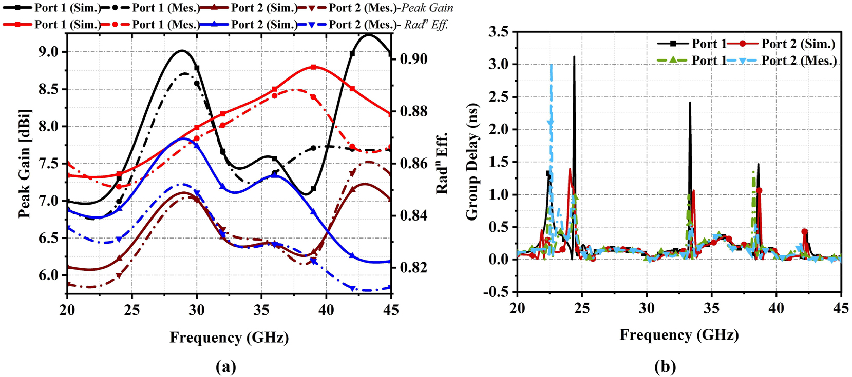
Measured and simulated response at port one and port 2 (a) peak gain & radiation efficiency (b) group delay.
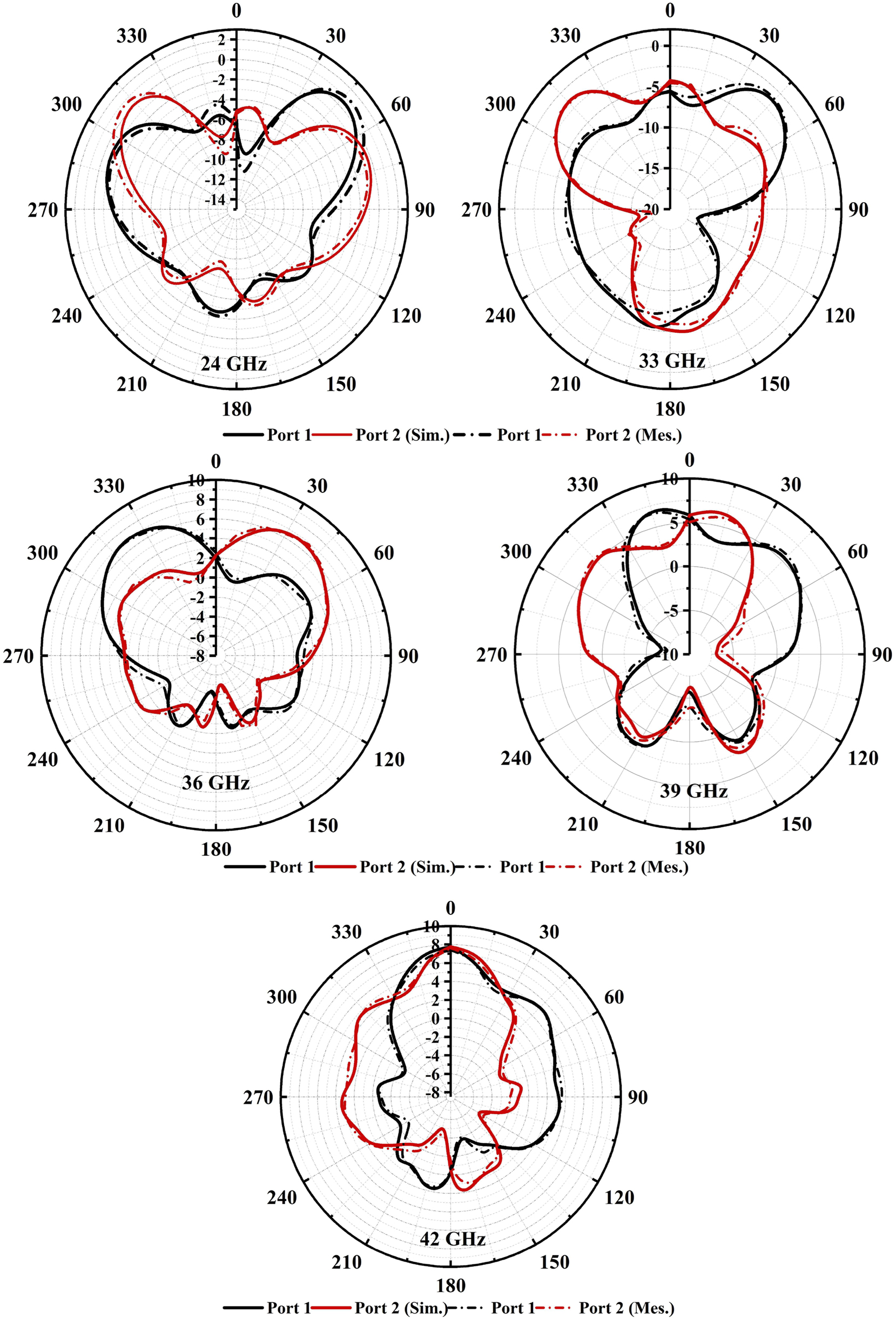
Beam-steering mechanism response at 24 GHz, 33 GHz, 36 GHz, 39 GHz and 42 GHz respectively.
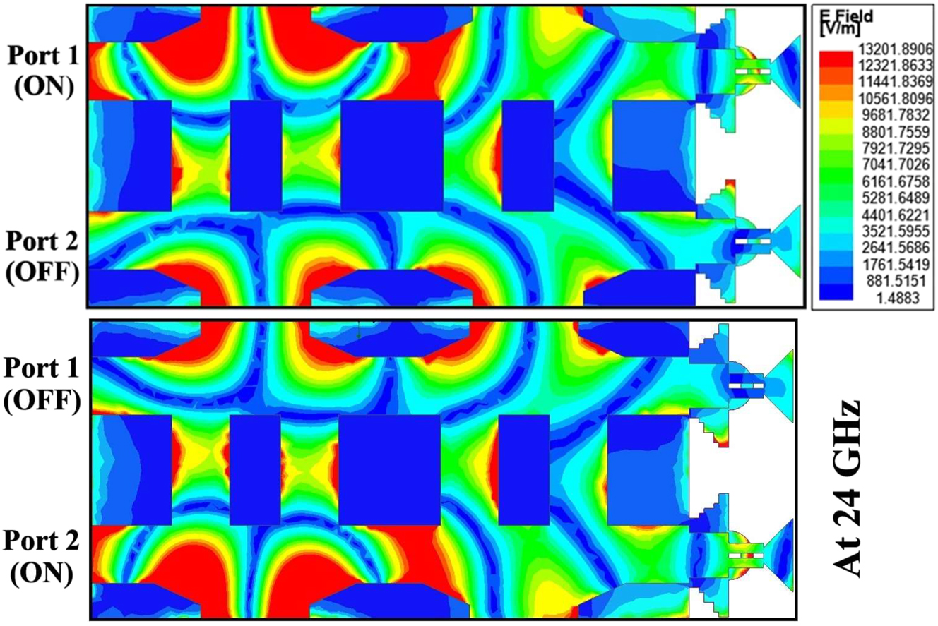
Current distribution over the antenna at 24 GHz for excited port 1 & 2 respectively.
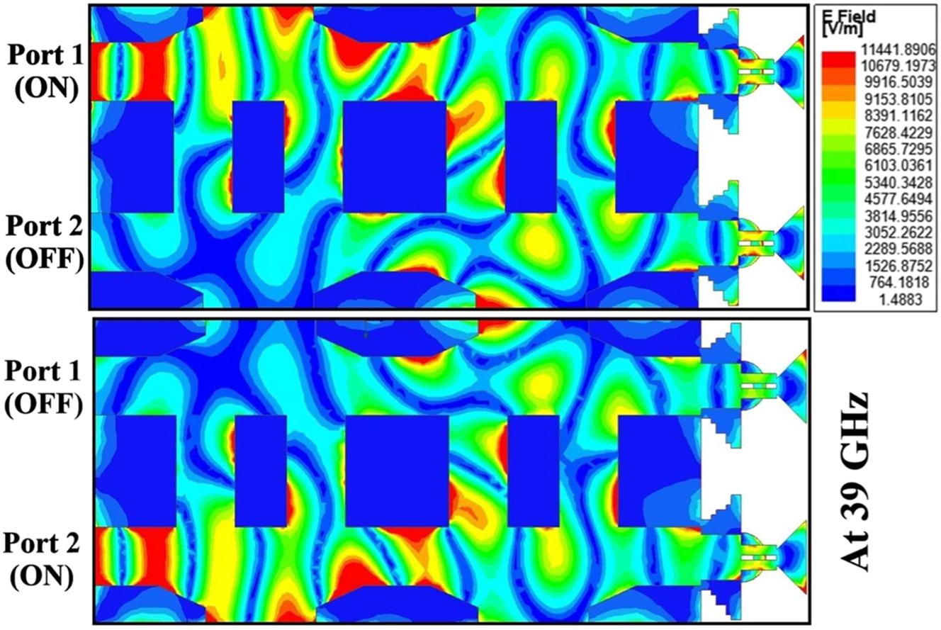
Current distribution over the antenna at 39 GHz for excited port 1 & 2 respectively.
Results of the proposed beam-steering antenna.
| Antenna type | Antenna size (mm3) | Op. Freq. | B.W % | Gain | Isolation | ECC | DG | MEG | Scanning angles |
|---|---|---|---|---|---|---|---|---|---|
| 2 × 2 BLC network |
12.11 × 25.58 × 0.8 | 24 GHz & 39 GHz | 17.4 % & 40 % | 9 dBi & 10.2 dBi | >20 dB | 0.0012 | 9.92 | <3 dB | ±45° ±75° ±180° |
Comparison of proposed antenna with recent work by the different authors.
| Ref. No | Antenna technique | Antenna size (λ0)3 | Op. freq. | B.W % | Isolation/ECC | Gain | Scanning angles | Applications |
|---|---|---|---|---|---|---|---|---|
| [22] | Single BLC network | 0.12 × 0.36 × 0.03 | 4.5–10 GHz | 75.8 % | |S12| = −13 dB | NA | 90.5° to 94.8° | 5G |
| [23] | Butler matrix | 0.8 × 0.8 × 0.04 | 3–7 GHz | 66.7 % | NA | 9.9 dBi | ±90° | 5G |
| [24] | SIW | 1.5 × 1.4 × 0.2 | 28 GHz | 35.7 % | |S12| ≤ 2 dB | 8.04 dBi | NA | mm-Wave |
| [25] | 2 Element DRA | 0.98 × 0.98 × 0.18 | 4.9 GHz & 28 GHz | 31.63 % & 21.5 % | ECC < 0.01 | 6.6 dBi & 12 dBi | ±50° | 5G |
| [26] | Patch | 0.52 × 0.94 × 0.04 | 3.5 GHz & 28 GHz | 7.4 % & 12.1 % | ECC = 0.03 | 6.9 dBi & 14.6 dBi | ±25° | 5G |
|
Proposed
Work |
2 Element BLC network | 0.96 × 2.01 × 0.06 | 24 GHz & 39 GHz | 17 % & 40 % |
ECC = 0.0012
|S 12 | > 20 dB |
9 dBi & 10.2 dBi | ±45° ±75° ±180° |
Radar, ISM-III and mm-wave |
-
Bold value shows the results of this proposed work and gets compared with other research work.
5 Conclusions
A 2 × 2 hybrid coupler based a beam-steering antenna has been proposed in this research article applicable for the Radar and millimetre wave applications. It covers the dual band having the bandwidth of 22.6–26.89 GHz & 30–45 GHz with radiation efficiency of 88 % and gain of 9 dBi and 10.2 dBi respectively. All observed response of the proposed antenna gets summarized in Table 1. At different operating frequencies a directional beam pattern at distinct angles is found with wide scanning angles. Desirable response of insertion loss, ECC, DG and MEG are observed which makes this antenna as a good candidate in multipath environment. A comparison has been made with some latest work done by some authors gets summarized in Table 2. Due to narrow beam pattern at different angles antenna is applicable for higher frequency applications by covering Radar, ISM-III band and millimetre wave applications.
Acknowledgments
No AI or ML tool has been used.
-
Research ethics: This research article has not been pubished or submitted to any other journal. This article is only submitting to your journal.
-
Informed consent: All individuals are included in this research or study.
-
Author contributions: The authors has accepted responsibility for the entire content of this manuscript and approved its submission.
-
Competing interests: The authors state no conflict of interest.
-
Research funding: None declared.
-
Data availability: The raw data can be obtained on request from the corresponding author.
References
[1] A. B. Patwary and I. Mahbub, “Electro-mechanical beam steering modeling to enhance the scanning range of UWB vivaldi antenna array,” in 2023 IEEE International Symposium On Antennas and Propagation and USNC-URSI Radio Science Meeting (USNC-URSI), Portland, OR, USA, 2023, pp. 519–520.10.1109/USNC-URSI52151.2023.10238208Suche in Google Scholar
[2] M. F. Hossain, D. Das, and M. A. Hossain, “A 5G beam-steering microstrip array antenna using both-sided microwave integrated circuit technology,” Int. J. Electr. Comput. Eng., vol. 14, no. 1, pp. 457–468, 2024, https://doi.org/10.11591/ijece.v14i1.pp457-468.Suche in Google Scholar
[3] Al-Amin, M. R., Malfajani, R. S., Baladi, E., and Sharawi, M. S., “Connected antenna arrays with beamsteering capability for on-package millimetre-wave applications,” IEEE Open J. Antennas Propag., vol. 5, no. 2, pp. 414–429, 2024. https://doi.org/10.1109/ojap.2024.3358373.Suche in Google Scholar
[4] D. Parsediya and P. Singhal, “Analysis of 5G Rotman beamforming lens antenna for higher beam angle and minimum phase error,” Frequenz, vol. 78, nos. 3–4, pp. 169–180, 2024. https://doi.org/10.1515/freq-2023-0239.Suche in Google Scholar
[5] M. Ikram, K. Sultan, A. T. Mobashsher, M. Moosazadeh, and A. Abbosh, “Wide-angle beam steering closed-form pillbox antenna fed by substrate-integrated waveguide horn for on-the-move satellite communications,” Sensors, vol. 24, no. 3, p. 732, 2024, https://doi.org/10.3390/s24030732.Suche in Google Scholar PubMed PubMed Central
[6] Qi, X., Li, F., Li, Z., Xu, K., Xu, Z., and Li, H., “2D steerable multi-beam antenna for concurrent wireless communication systems,” IEEE Trans. Circuits Syst. II Express Briefs, vol. 71, no. 6, pp. 3026–3030, 2024. https://doi.org/10.1109/tcsii.2024.3358837.Suche in Google Scholar
[7] D. Duraj, L. Leszkowska, W. Kalista, K. Trzebiatowski, L. Kulas, and K. Nyka, “Energy efficient beam .control for 5G antennas,” in Technologies Enabling Future Mobile Connectivity & Sensing, River Publishers, 2024, pp. 87–101.10.1201/9781032633039-7Suche in Google Scholar
[8] Wang, Y., Xue, Q., Hu, Z., and Liao, S., “Mixed modes-enabled element-level beamforming antenna with enhanced isolation for phased array applications,” IEEE Trans. Antennas Propag., vol. 72, no. 5, pp. 4577–4582, 2024. https://doi.org/10.1109/tap.2024.3349675.Suche in Google Scholar
[9] Singh, C., Sharma, C., Tripathi, S., Sharma, M., and Agrawal, A., “A comprehensive survey on millimeter wave antennas at 30/60/120 GHz: design, challenges and applications,” Wirel. Pers. Commun., vol. 133, pp. 1547–1584, 2023. https://doi.org/10.1007/s11277-023-10828-z.Suche in Google Scholar
[10] S. Kausar, A. U. Kausar, M. U. Hadi, and H. Mehrpouyan, “Multi-beam high gain steerable transmitarray lens for satellite communication and 5G mm-Wave systems,” AEU – Int. J. Electron. Commun., vol. 173, p. 154888, 2024, https://doi.org/10.1016/j.aeue.2023.154888.Suche in Google Scholar
[11] Golla, R. and Nelaturi, S., “Antipodal vivaldi array MIMO antenna for 5G FR2 applications at 28 GHz with improved isolation,” Frequenz, vol. 78, no. 7–8, pp. 381–387, 2024. https://doi.org/10.1515/freq-2023-0399.Suche in Google Scholar
[12] Y. Xu, H. Zhu, and Y. J. Guo, “Compact multi-beamforming networks based on generalized joined coupler matrix with flexible beam angles and low sidelobe levels,” IEEE Open J. Antennas Propag., 2023, https://doi.org/10.1109/ojap.2023.3336764.Suche in Google Scholar
[13] Wen, J. M., Yu, C., Li, Y. X., Pan, Y. M., and Zheng, S. Y., “A compact dual-beam steering antenna array based on a simplified beamforming network,” IEEE Trans. Antennas Propag., vol. 71, no. 9, pp. 7620–7625, 2023. https://doi.org/10.1109/tap.2023.3287402.Suche in Google Scholar
[14] M. H. Jwair and T. A. Elwi, “Steerable composite right–left‐hand‐based printed antenna circuitry for 5G applications,” Microw. Opt. Technol., vol. 65, no. 7, pp. 2084–2091, 2023, https://doi.org/10.1002/mop.33666.Suche in Google Scholar
[15] Almalki, M., Alshammari, B., and Podilchak, S. K., “Dual-circularly polarized single-element patch antenna with compact multi-port feeding,” IEEE Antennas Wirel. Propag. Lett., vol. 23, no. 2, pp. 648–652, 2023. https://doi.org/10.1109/lawp.2023.3331577.Suche in Google Scholar
[16] R. Khajeh MohammadLou, T. Aribi, T. Sedghi, and B. S. Virdee, “A multi-beam circularly polarised Fabry-Perot resonator antenna array using SIW for X-Band applications,” Int. J. Electron., pp. 1–18, 2023, https://doi.org/10.1080/00207217.2023.2278436.Suche in Google Scholar
[17] M. Shaw and Y. K. Choukiker, “Reconfigurable polarization and pattern microstrip antenna for IRNSS band applications,” AEU – Int. J. Electron. Commun., vol. 160, p. 154501, 2023, https://doi.org/10.1016/j.aeue.2022.154501.Suche in Google Scholar
[18] Z. Shafiq, D. E. Anagnostou, and S. K. Podilchak, “Self‐calibrating circuit for phase correction to support phased array antenna systems,” Electron. Lett., vol. 59, no. 22, p. e13031, 2023, https://doi.org/10.1049/ell2.13031.Suche in Google Scholar
[19] Barik, R. K., Koziel, S., and Bernhardsson, E., “Design of frequency-reconfigurable branch-line crossover using rectangular dielectric channels,” IEEE Access, vol. 11, pp. 38072–38081, 2023. https://doi.org/10.1109/access.2023.3267486.Suche in Google Scholar
[20] Ansems, R., Federico, G., Smolders, A. B., and Caratelli, D., “Multi-mode phased antenna array for mm-wave user terminals with ultra-wide-angle scanning capabilities,” IEEE Trans. Antennas Propag., vol. 72, no. 1, pp. 1021–1026, 2023. https://doi.org/10.1109/tap.2023.3315843.Suche in Google Scholar
[21] You, J. and Dong, Y., “Miniaturized planar pattern reconfigurable antenna for smart wi-fi applications,” IEEE Antennas Wirel. Propag. Lett., vol. 23, no. 1, pp. 109–113, 2023. https://doi.org/10.1109/lawp.2023.3318328.Suche in Google Scholar
[22] F. H. Ahmed, R. Saad, and S. K. Khamas, “A novel compact broadband quasi-twisted branch line coupler based on a double-layered microstrip line,” Micromachines, vol. 15, no. 1, p. 142, 2024, https://doi.org/10.3390/mi15010142.Suche in Google Scholar PubMed PubMed Central
[23] J. Temga, T. Shiba, and N. Suematsu, “A compact broadside coupled stripline 2-D beamforming network and its application to a 2-D beam scanning array antenna using panasonic megtron 6 substrate,” Sensors, vol. 24, no. 2, p. 714, 2024, https://doi.org/10.3390/s24020714.Suche in Google Scholar PubMed PubMed Central
[24] Q. H. Lin, D. Hou, L. Wang, P. Chen, and Z. Luo, “A millimeter-wave broadband multi-mode substrate-integrated gap waveguide traveling-wave antenna with orbit angular momentum,” Sensors, vol. 24, no. 4, p. 1184, 2024, https://doi.org/10.3390/s24041184.Suche in Google Scholar PubMed PubMed Central
[25] Muhammad, A., Khan, M. U., Shamsaee Malfajani, R., Sharawi, M. S., and Alathbah, M., “An integrated DRA-based large frequency radio antenna system consisting of a MM-wave array and a MIMO antenna for 5G applications,” IEEE Open J. Antennas Propag., vol. 5, no. 2, pp. 368–378, 2024. https://doi.org/10.1109/ojap.2024.3349455.Suche in Google Scholar
[26] X. H. Ding, W. W. Yang, H. Tang, L. Guo, and J. X. Chen, “A dual-band shared-aperture antenna for microwave and millimeter-wave applications in 5G wireless communication,” IEEE Trans. Antennas Propag., vol. 70, no. 12, pp. 12299–12304, 2022, https://doi.org/10.1109/tap.2022.3209220.Suche in Google Scholar
© 2024 Walter de Gruyter GmbH, Berlin/Boston
Artikel in diesem Heft
- Frontmatter
- Research Articles
- Reconfigurable frequency selective surface based absorber realized using interlocking blocks
- Dual band beam steering antenna using branch line coupler network for higher band applications
- High-efficiency quad-band RF energy harvesting system with improved cross-coupled differential-drive rectifier
- A novel miniaturized microstrip filtering power divider with high selectivity based on composite right/left-handed (CRLH) concept
- High-selectivity wideband bandpass filter based on quintuple-mode stub-loaded resonator and defected ground structures
- Design of a high selective triple band integrated reconfigurable filtering antenna for wideband and narrowband applications
- A novel ultra-wideband end-fire antenna based on spoof surface plasma polaritons
- Metamaterial-based transmit and receive antennas for wireless image transfer at 5.8 GHz
- Design of a MIMO implantable antenna with ultra-miniaturized volume and reduced SAR
- ANN modeling for predicting muscle-implanted antenna performance for skin and fat thickness variations at 2.45 GHz