Modelling, design and parametric analysis of a levitation based energy harvester
-
Prajwal Kogodu Thirthappa

 und
Manickavasagam Krishnan
und
Manickavasagam Krishnan

Abstract
Levitation based energy harvester (LBEH) is an energy harvesting technology which is used to convert the existing kinetic energy into electrical energy. The technique utilizes a levitating magnet which in a closed container vibrate or moves for the subjected vibrations. An outer coil which will extract energy into electrical voltage is carefully selected or designed or the rating. In this research work, a conventional LBEH is designed, simulated, and studied for a particular vibration data. The same is carried out in the FEM analysis software. The system is also mathematically derived and analyzed in the numerical tool. The results obtained from the numerical and FEM tool are compared. At the end of the research work, a parametric study is carried out for the variations in the input characteristics such as frequency, nature of vibrations and other parameters. Results obtained indicate that the power developed is maximum with a value of 0.7 V and 10 mW for the designed natural frequency of 10 Hz and decreases on either side as the bandwidth varies from 5 to 15 Hz.
Introduction
Energy harvesting is a method of extracting electrical energy from other sources of energy such as heat, light, vibration, and motion. The amount of electrical energy extracted depends on the type and of the input available. The conversion technique employed also is dependent on the amount of energy harvested.
Energy harvesting technology is widely popular in the recent past as the need for a small amount of power is increasing day by day with the advent of small-scale power electronics like wearables and other wireless sensor networks (Gros et al. 2017). The energy requirements of these small-scale electronics and portable devices are usually satisfied by a battery using piezoelectric technology and electromagnetism (Khaligh, Zeng, and Zheng 2009). But due to the increasing carbon footprint, the United Nations (UN) promotes the use of renewables. Hence the concept of energy harvesting as a small-scale renewable energy came into light in 1996 (Williams and Yates 1996).
The advantage of energy harvesting is that the need for frequent replacement of the batteries is reduced. This helps in the increase continuous usage of wireless sensor networks which are in an environment which is exceedingly difficult to access/neither accessible (Guruacharya and Hossain 2017). The use of vibration-based energy harvesting is gaining popularity as vibrations are present everywhere in the environment and it can be extracted from the human body motion. The vibration energy harvesting also known as kinetic energy harvesting can be modified for any level of power extraction based on the design of the energy harvester (Kulah and Najafi 2008; Yen and Lang 2006).
The concept of energy harvesting was first conceptualized by Williams and Yates in literature. In literature, the free body diagram of the generalized energy harvester is developed and a mathematical model for the same is also derived.
As seen from Figure 1, any vibrating energy harvester device can be modelled as mass – spring – damper system. The equivalent mass is the amount of the mass of the magnet. The damper system is equivalent to the electromagnetic force that is experienced by the electromagnetic system (Cannarella et al. 2011). Spring stiffness is also the stiffness of the system that is experienced by the magnetic system. This spring stiffness constant depends on the type of electromagnetic energy harvesting system. Spring stiffness depends on the force of the magnetic field produced by the two magnets. This is discussed in detail in the upcoming sections.
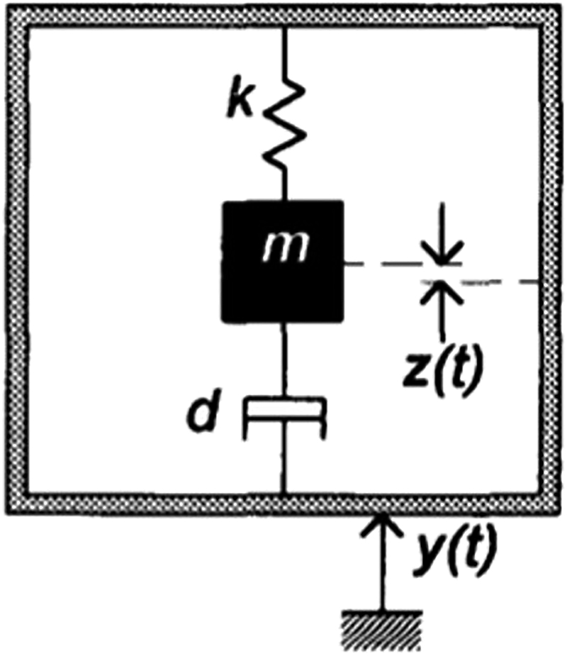
Schematic diagram of the energy harvesting device (Williams and Yates 1996).
The literature suggests that there is no preliminary design for the energy harvesting design. The design depends on the type of device that the energy harvesting device tends to be like a primarily a current or a voltage device. The input to such a type of harvester is always assumed to be sinusoidal vibration input. The energy harvesting device is subject to a vibration which initiates the movement of the magnet as represented by the mass in Figure 1. If the coils are represented by the dashpot, due to the relative displacement between the coil and the magnet an emf will be induced in the coil which can be stored or consumed as required.
The system described in Figure 1 is an inertial device which needs to be anchored mechanically to any one point as in the literature (Khan and Iqbal 2018). This is different from the rotational electromechanical system like the dynamo that needs to be anchored to more than one point. An inertial generator can simply be attached to any moving body to generate electricity. Similar approach can be seen in Lee and Chung (2016).
Levitation based energy harvesting (LBEH)
This method of energy harvesting is widely used in the extraction of electrical energy from the vibrations. In this method, three magnets, two stationary magnets and one levitating magnet is used to convert the mechanical energy into the electrical energy. The advantage of this method is that the friction is reduced as there is no spring/mechanical system involved. Due to this, large amounts of electrical energy can be extracted from the system. The system is as described in Figure 2.

Schematic diagram of the LBEH (RADU OLARU ET.ALL).
As seen from Figure 2, there are two magnets, each one stationary at the ends of the harvester. There is a levitating magnet in the middle, in the opposite polar direction as that of the fixed magnet at the top and bottom of the harvester. These fixed magnets provide a magnetic repulsive force for the magnet at the middle which is also called the levitating magnet. There is a coil around the levitating magnet which is helpful in extracting the electrical energy from the vibrations which are subjected to the base of the energy harvester.
The design of such LBEH system requires the design of the following based on the input vibrations that are subjected to the energy harvester and the output as required from the LBEH systems:
1. Design of the magnetic circuits
2. Design of the coil
This design is usually carried out in any FEM software and the quantities are optimised based on the output that is required from the system (Bernal and García 2012; Li et al. 2019).
In this model as seen in Figure 2, there exists a magnetic restoring force which is equivalent to the restoring force of the spring if it would have been as seen in Figure 1. In the design of such magnetic levitation-based energy harvester, the restoring force is calculated. The total restoring force is the sum of the individual restoring forces from each of the top magnet and the bottom magnets. These values of the restoring forces are usually obtained from the numerical simulations.
The practice of design of the energy harvester is that the restoring force should always be made equal to the input force that is given as a vibration input. Hence if these forces are made equal, the system will vibrate at resonant frequencies. This helps to extract more energy/power from the energy harvesting system.
The advantage of LBEH system is that electrical energy can be generated from lower amounts of vibrations as well. This can be used to power up electrical devices which are consuming less energy. The applications include wireless powered sensors, smart watches, flow meters which are remotely monitored.
There are also few disadvantages with this system. The main disadvantage is that this energy harvester is very much dependent on the frequency of the input vibrations. If the system is designed for a particular resonant frequency and then if the vibration frequencies is varied widely, the system will not be generating required amount of power.
The optimisation of the LBEH is also challenging as there are too many parameters to vary (Sun et al. 2012). Hence for the optimisation of the LBEH it is always preferable to have more than one constraint in the optimisation process. Usually, in the literature, the optimisation is the separate topic of interest that is carried out by the researchers using many sophisticated or complex algorithms or tools (Williams and Yates 1996).
Modelling and analysis of the levitation based energy harvesting (LBEH)
The levitation-based energy harvester used to generate electricity from the vibration is shown in the previous section. In this section, a detailed review of the technical aspects related to the design of the energy harvester is discussed. A mathematical model is derived from the set up. The same model is simulated using MATLAB and the results are analysed.
Structure of levitation based energy harvester (LBEH)
Saha et al. (2008) suggested the LBEH for extracting the electrical energy from the human body motion. The system consists of two stationary magnets and a repulsive levitating magnet as shown in Figure 2.
As seen from Figure 3, a moving magnet is surrounded by the stationary coil. The movement of the magnet is used to generate electricity using a simple induction principle. The movement of the magnet is caused by the vibrations which are subjected to the base of the energy harvester.
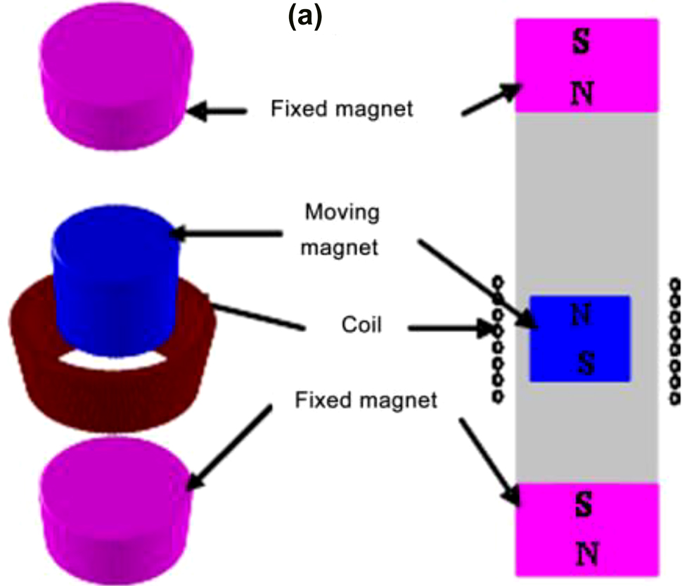
Exploded view of LBEH (Saha et al. 2008).
The same concept of the LBEH is also discussed in the (Williams and Yates 1996). The equivalent model of such energy harvester is discussed in the paper. From the equivalent model, a mathematical analysis is performed to understand the characteristics of the LBEH.
The mass-spring system consists of a seismic mass, a spring and a frame as shown in Figure 4.
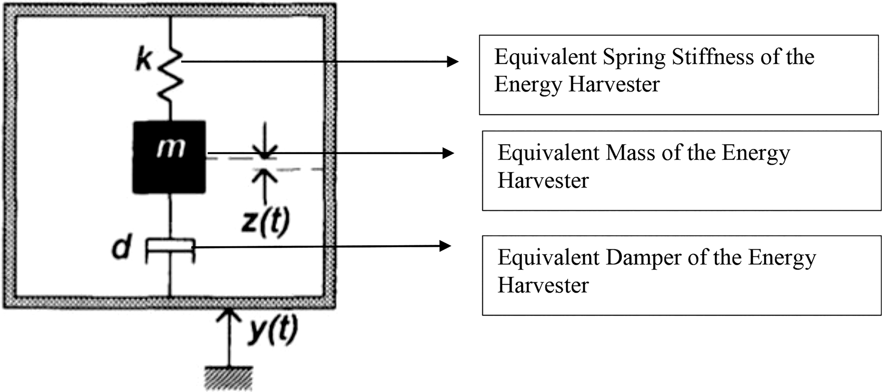
Equivalent mass spring damper system of an electromagnetic harvester.
The significance of each parameter is as follows,
m – Mass of vibrating block
y(t) – The vibration displacement of the system with time.
z(t) – Displacement of mass caused by y(t).
k – Spring constant.
cm – Mechanical damping coefficient.
ce – Electrical induced damping coefficient.
c – Damping coefficient of the system (c = ce + cm).
The differential equation of motion for the system can be described as
Assume the external input to be sine excitation vibration,
Solving the above equation for the following assumption, the mass in the harvester is nothing but a Magnet.
Resonance frequency of the EH structure should be made equal to the natural frequency of the vibration.
Electromagnetic and mechanical damping are made equal using the construction parameters.
The power that can be obtained by the energy harvester is given by,
Choice of damping factor:
Damping factor can be varied by varying the electrical load resistance for the given design.
The power generated by the harvester at resonant frequency is given by
The mathematical model of the linear generator using mass-spring-damper system is arrived at considering all factors of the output. The assumption is made that the mass of the vibrating source is greater than the seismic mass of the energy harvester. This will provide an easier analysis of the energy or power generated from the energy harvester. First the force balance equations of the system are derived and finally the generated power is obtained for the sinusoidal input vibration source.
The mathematical model reiterates that generated power is maximum for the resonant frequencies of the generator. It is also clear from the mathematical model that the generated power is directly proportional to the cube of the input vibrational frequency. Hence higher power is generated for higher frequencies and vice versa.
MATLAB simulation and analysis of the mathematical model
Equations (1–6) which are discussed in the section consisting of LBEH is simulated in the MATLAB to understand the characteristics of the energy harvester based on levitation. The analysis is performed based on the fact that the energy harvester is designed to an input vibration of very low frequencies. This is done as in the literature the energy harvester is mostly designed and developed for higher frequencies.
As in the equations it can be seen that the power developed is directly proportional to the cube of the input vibration frequency, for low frequencies, it is understood that the power developed will also be small. Hence in order to compensate for the lower amount of the power for low frequencies it should be noted that the amount of mass or the maximum amount of movement of mass i.e., magnet should be maximum.
The equations are programmed in the MATLAB and different characteristics of the LBEH are obtained and analysed. As it is discussed before, the energy harvester is analysed for the low frequency applications. The frequency of the vibration is considered as low if the frequency is in the range of 0–20 Hz. Hence in this research work, the energy harvester is designed and analysed for the nominal frequency of 10 Hz.
The mathematical model addresses the necessity of calculating the mass of the magnet for the extraction of the energy from the harvester. Based on the preliminary calculations and deliberations, the following parameters are arrived at to be used in the MATLAB simulations:
Mass of the moving/levitating magnet: 50 mg
Dominant frequency of the environment: 10 Hz
Maximum amplitude of vibration: 20 mm
Damping ratio: 0.3
There is always a trade-off between the maximum mass of the magnet and the power generated. Even though from the primary equations, it can be seen that the power developed is directly proportional to the mass of the magnet, it is not so. This is because as the increase in the mass of the magnet the ability of the movement of the magnet decreases thereby forcing the power developed to be less. The above simulation parameters were used in the MATLAB and the results were obtained as in Figures 5 and 6.
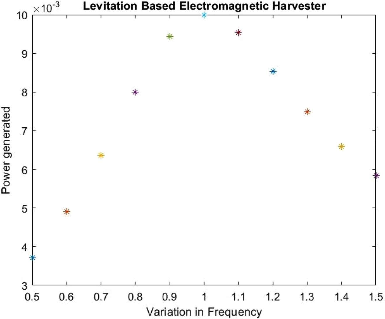
Power generated in the LBEH.
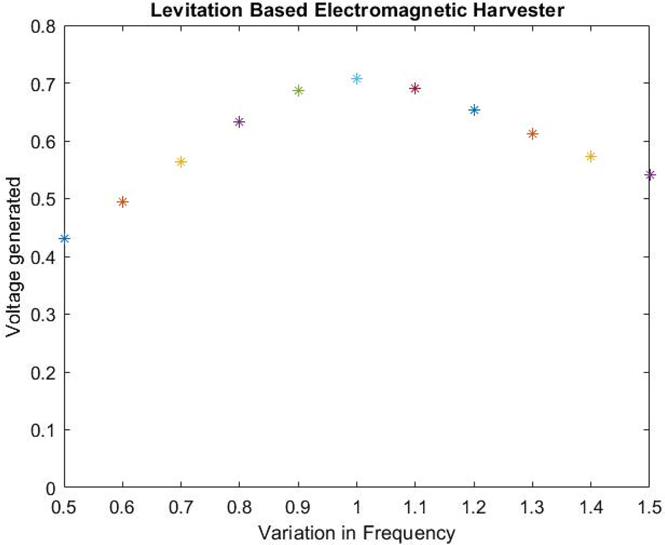
Voltage generated in the LBEH for 50 ohms.
As it can be seen from Figure 5, the maximum power that can be generated is 10 mW. The variation in the frequency that is mentioned in the x-axis indicate the change of frequency for the designed frequency. It means that the energy harvester which is designed for the 10 Hz can also operate at other frequency which is indicated as 0.5 and 1.5 still, but with the limited power range generated. As it can be seen from the figure, the power generated varies with the variation to the input frequency. Hence it is always desirable to operate the energy harvester with the designed frequency so as to obtain the maximum output power.
For the analysis purpose, the resistance value is considered to be 50Ω. The voltage is also calculated and the same is shown in Figure 5 as well. The maximum voltage that the energy harvester can generate is 0.7 V for the 10 Hz frequency. As the variation in the frequency is induced, the system will also generate lower amount of voltage as in the case of power.
The results obtained indicate that the power/voltage generated from the energy harvester will be maximum for the particular resonant frequency or the dominant frequency. Hence the energy harvester needs to be operated at the same resonant frequency/dominant frequency or at least in the near band range of the dominant frequency so as to obtain the desired maximum power/voltage. The results are in conjunction with the results as obtained in Williams and Yates (1996).
Simulation of levitation based energy harvesting (LBEH) in Finite Element Analysis (FEA)
The MATLAB simulations were obtained as a reference for carrying out the simulations in the Finite Element Analysis (FEA). The FEA was carried out to obtain the voltage from the input vibrations. The system to be simulated in the FEA is carried out the COMSOL as comparable in the literature Bernal and García (2012). The LBEH with vertical type of vibration is simulated in the COMSOL with the specifications as modelled in the previous section is used (Saha et al. 2008).
As discussed in the previous sections, the energy harvester is simulated for low frequency applications. The low frequency applications include the vibrations which are captured in the ship, on any vertical type of vibrating devices on the deck of the vehicle and the machinery in the industries (Lin et al. 2009).
As obtained through the literature, the vibrations from the sea are of the value of 10–20 Hz with the vibration amplitude of around 20 mm. Hence in this part of the research a COMSOL model was developed and simulated for the mentioned values. The detailed steps for the modelling and analysis are discussed in the present part of the article.
The system to be modelled in COMSOL is same as mentioned in Figure 2. The energy harvester will consist of the two stationary magnets in the top and bottom of the energy harvester. In the middle a levitation-based magnet is modelled. This magnet is levitating because of the pole direction of the stationary magnet and the levitating magnet. The poles will be arranged so as to oppose the magnetic faces each other to make the magnet levitate.
The energy harvester modelled in the COMSOL is the axisymmetric model where the model is modelled only with the half of the axis and the same will be replicated automatically while obtaining the results. The system developed is as shown in Figure 6.
As seen from Figure 7, there are two magnets which are stationary at the top and bottom of the energy harvester. A magnet is levitating at the middle of the harvester. The power from the harvester is extracted using a coil which is wound in the middle of the harvester. The specifications of the LBEH designed in the COMSOL is as follows:
1. Stationary Coil:
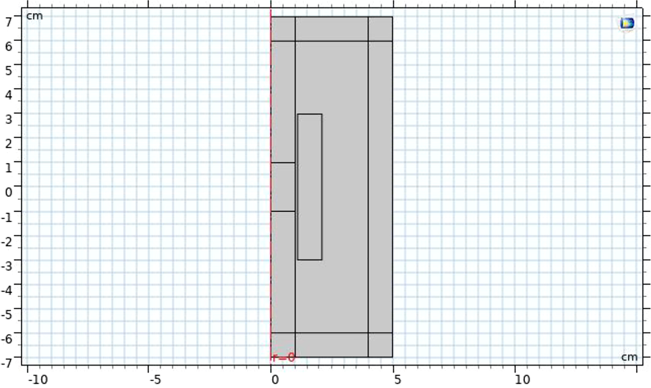
LBEH designed in the COMSOL.
Width – 1 cm; Length – 8 cm; Number of turns – 800 turns, copper wire.
2. Levitating Magnet:
Width – 1 cm; Length – 2 cm; Magnetic field strength – 1.2 T, Permanent magnetic material: neodymium magnet (NdFeB).
3. Stationary Magnets:
Width – 1 cm; Length – 1 cm; Magnetic field strength – 1.2 T, Permanent magnetic material: neodymium magnet (NdFeB).
4. Input vibration frequency: 10 Hz.
5. Input vibration amplitude: 20 mm.
In COMSOL, both the stationary and transient analysis were performed to extract the possible energy from the energy harvester. The output voltage from the energy harvester was obtained for the specification as mentioned in Section 2 of the article.
The results as obtained from the COMSOL is shown in the following figures.
The result in Figure 8 shows the magnetic flux lines in the meshed model of the axisymmetric model of the energy harvester device. As it can be seen in the figure maximum flux density is concentrated in the levitating magnet. There is also slight magnetic flux density in the stationary magnet as compared to the levitating magnet. As the dimension of the stationary magnet is less compared to the levitating magnet, the flux density is also comparatively low.
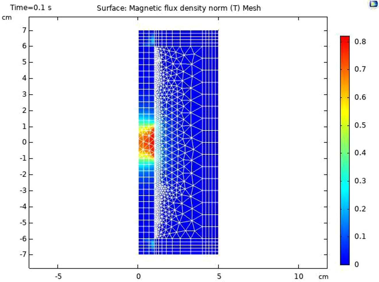
Magnetic flux lines in 2D Model.
The theoretical and the practical values of the flux densities in normally not matching due to leakage flux and remnant flux density. As it can be seen from the result obtained, the practical values of the flux density are less than the theoretical i.e., theoretical value given as the input to the system was 1.2 T whereas the practical value of flux density as seen from the graphs are only up to 0.8 T.
Figure 9 shows the same result as of Figure 8 but with a 3D view to the LBEH developed.
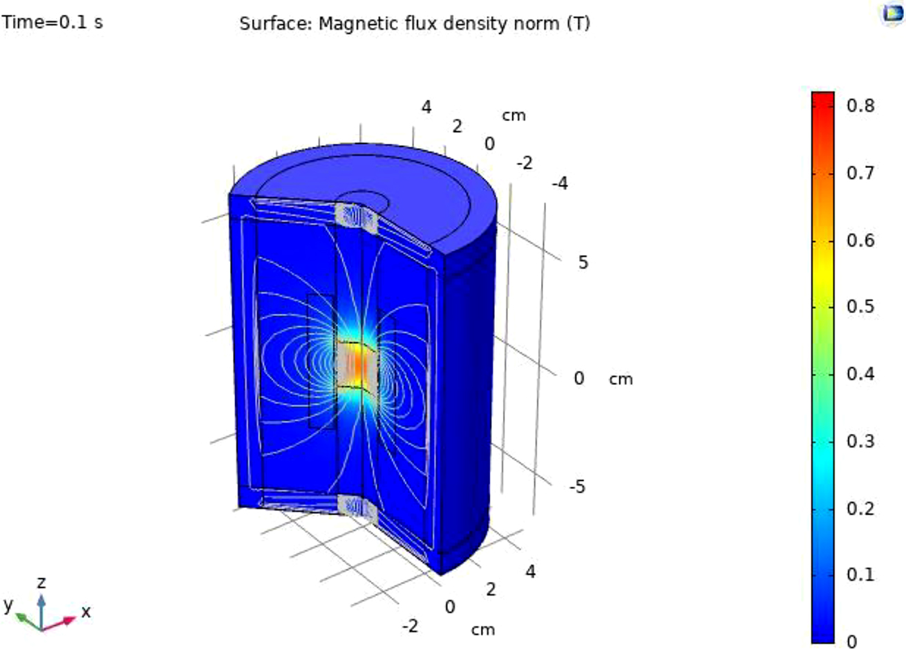
Magnetic flux lines in 3D Model.
The results from Figures 8 and 9 indicate that the lines of flux are originating from the north pole of the levitating magnet and terminates at the South Pole. The same is true for the stationary magnets which are at the top and bottom of the energy harvester.
The flux lines in the levitating magnet cuts the stationary coil and the voltage is generated in the coil due to Faraday’s law of induction.
Transient simulation of the LBEH
The energy harvesting device based on the LBEH is simulated for the transient simulation to obtain the voltage from the input vibration. The system as discussed before is subjected to the low frequency vibrations of 10 Hz and the AC Voltage is obtained. The system when subjected to the vibration from the base of the harvester, vibrates and the reference frame is moved. When the reference frame is subjected to vibration, the levitating magnet also subjected to vibration and hence due to the relative motion between the conductor and the levitating magnet, an AC voltage is induced in the energy harvester as shown in Figure 10.
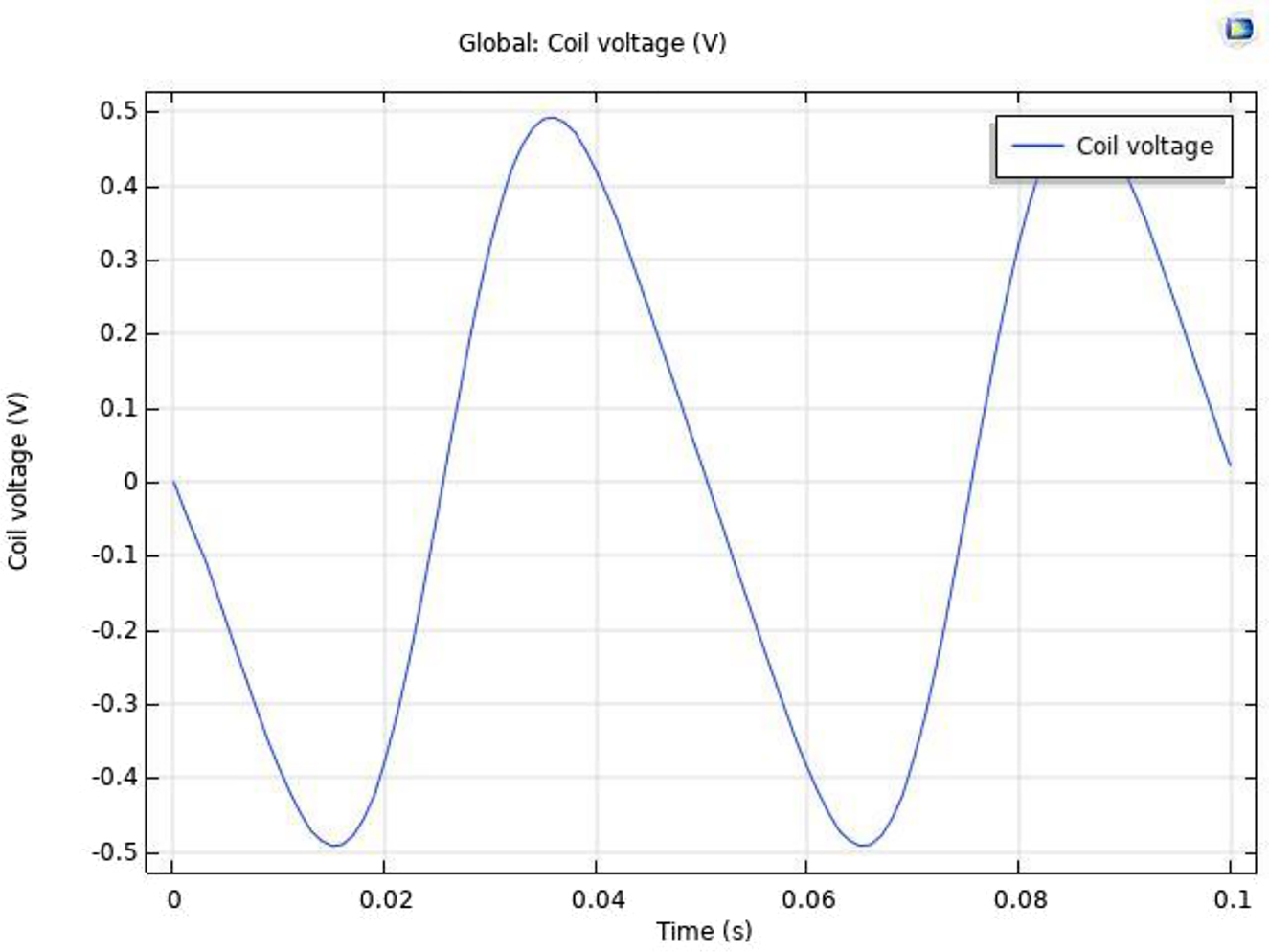
Induced voltage in the coil.
As seen from Figure 10, the maximum voltage that is generated in the coil is 0.5 V. The voltage is the in form of sinusoidal due to the input vibration. As the input vibration is also in the form of sinusoidal, hence the output in the system will also be in the form of sinusoidal.
The maximum voltage generated from the energy harvester obtained from the FEA in COMSOL agrees with the result obtained from the mathematical simulation as shown in Figure 6. As seen from Figure 6, the maximum voltage obtained from the numerical simulation/MATLAB is 0.7 V. But the maximum voltage obtained from the FEA simulation as in Figure 10 is 0.5 V. Therefore, a difference of 0.2 V is present between the simulations. This is due to the leakage flux in the energy harvester. The leakage flux and the remnant flux density is not considered in the numerical simulations.
Parametric studies of LBEH in FEA
Parametric variation studies are one of the important studies that is conducted in any research to assess the correctness of working of the model. It is also performed to obtain the boundary limits of the working range of any equipment to be designed. In this research work, parametric studies are carried out in the simulation environment to obtain the working range of the LBEH and understanding it’s characteristics in a clearer and better way.
No of turns V/s voltage generated
The primary criteria in designing any generator or harvester is to design the number of coil that can be fixed in order to generate the required amount of voltage. Hence this fixed parameter, is now varied in the parametric analysis and the voltage is varied as a function of the number of coil turns. The results can be seen in Figure 11.
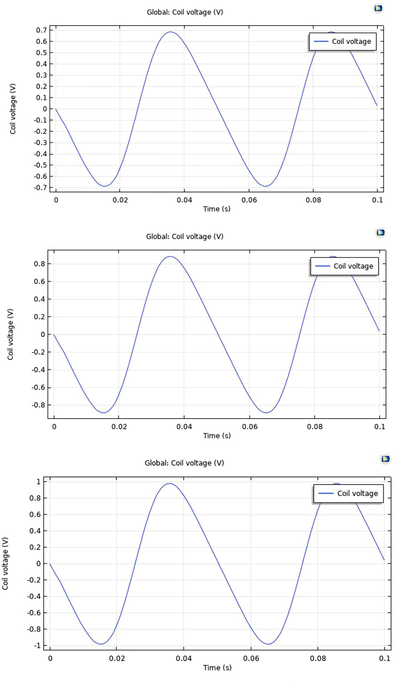
Voltage variation w.r.t. no of turns.
As seen from the below figures, the relationship between the number of turns in the coil and the output voltage is directly proportional. This is also plotted and depicted in Figure 12. It is also to be noted that practically, the number of turns that can be increased has a limit that it can fit into the dimension of the LBEH.

Parametric variations of No. of turns versus V/g.
Displacement of the magnet V/s voltage generated
As seen from the primary equations and general understanding, the levitating magnet provides more voltage if it can travel maximum distance of the coil. Hence it is obvious to design a LBEH with maximum movement allowed for the levitating-based magnet. It is also understood, that practical limitations exists for the maximal allowable limit for the displacement of the levitating magnet. The same is shown in the below Figures 13 and 14.
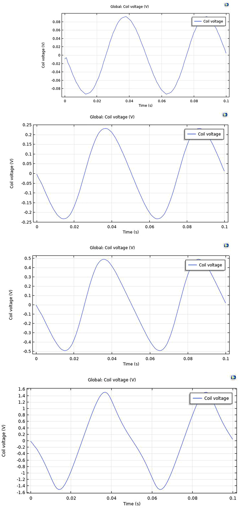
Magnet displacement V/s vg generated.

Parametric variations – displacement versus V/g.
Frequency of vibration V/s voltage generated
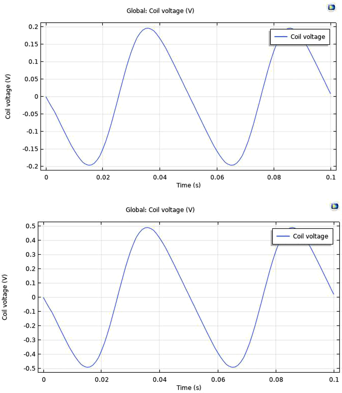
As it is seen from the mathematical model and the preliminary MATLAB simulation, the voltage generated from the LBEH is maximum only when the input frequency of vibration is equal to the designed natural frequency of the harvester. Hence voltage generated or the power generated curve will be maximum at the designed natural frequency of the LBEH. This is also simulated and proved in the FEM and the same is shown in Figures 15 and 16.
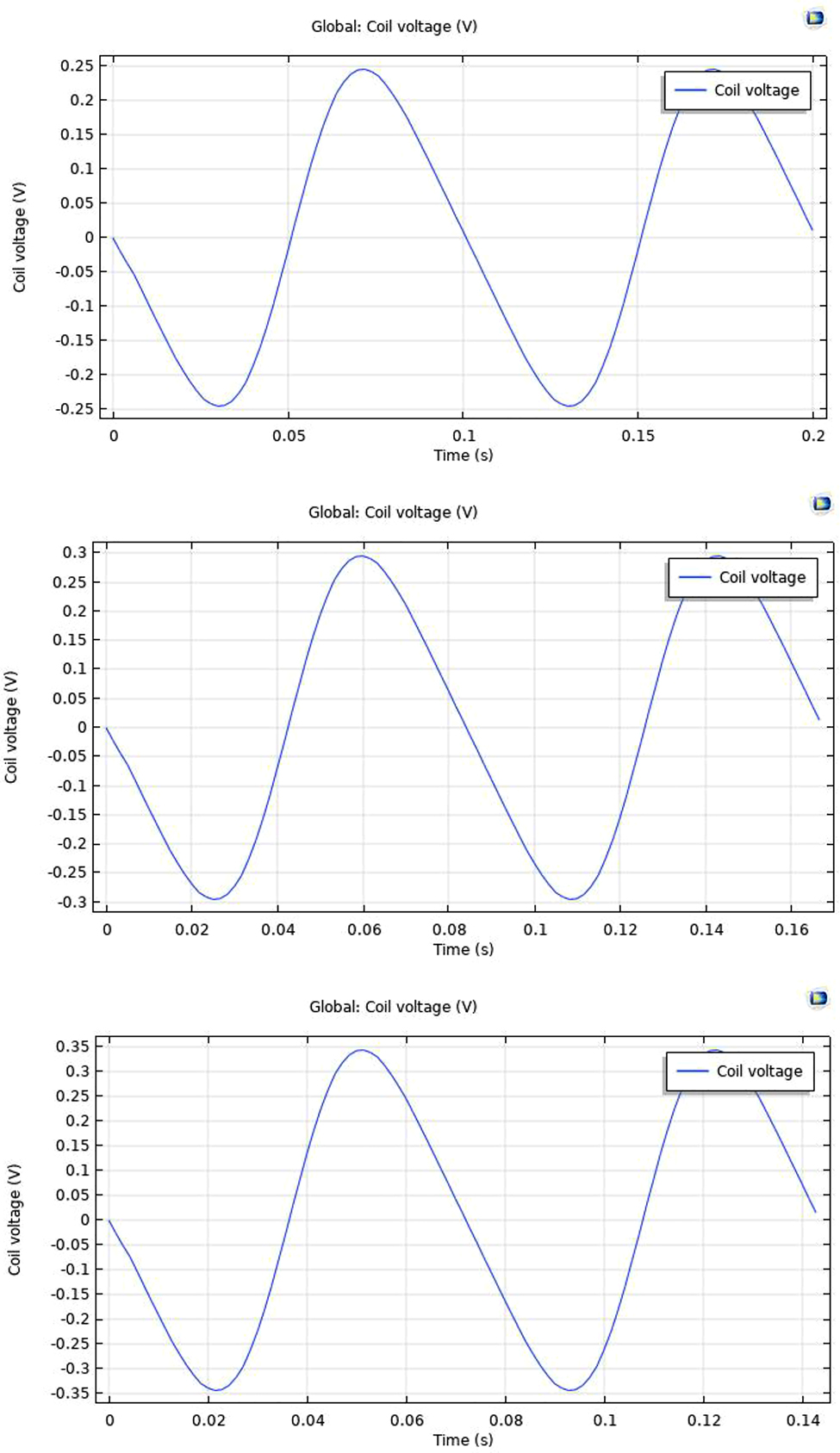
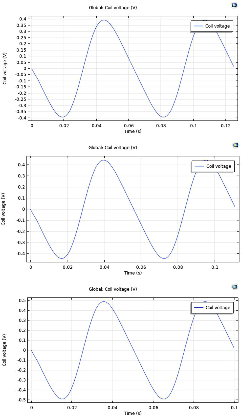
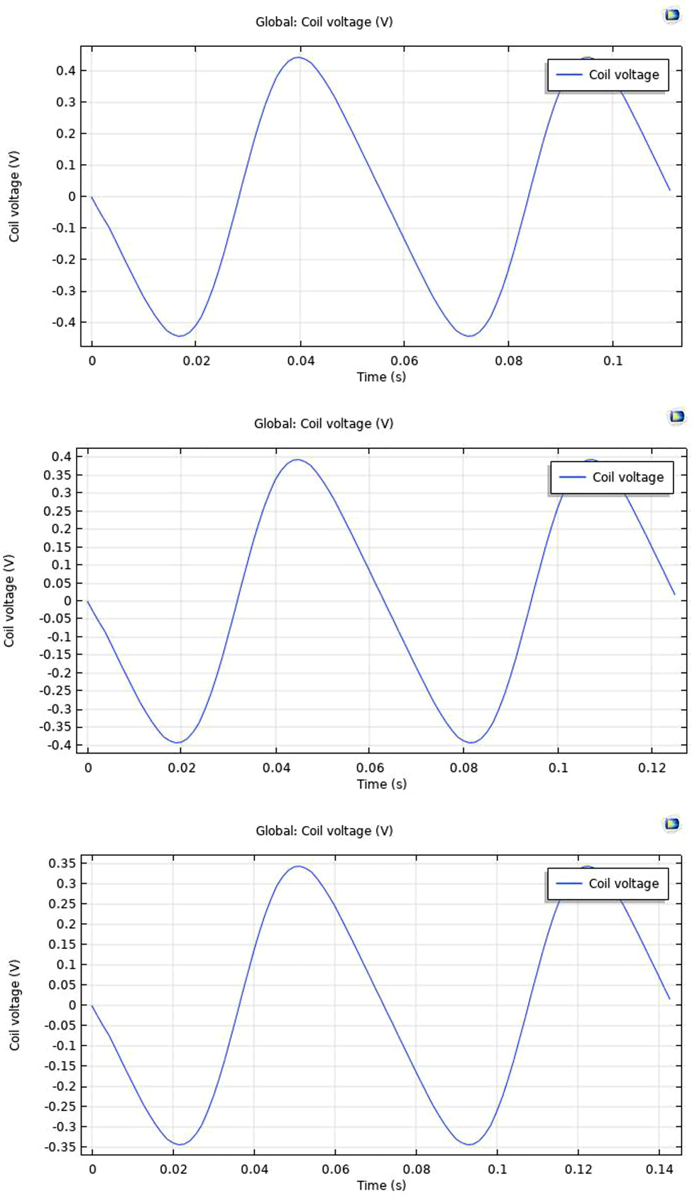
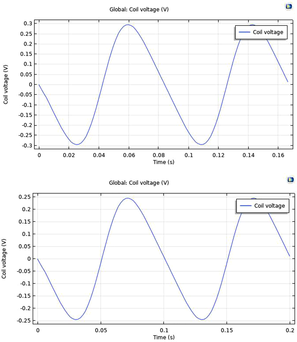
Frequency variations V/s voltage.
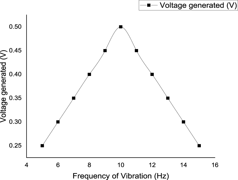
Parametric variations – frequency V/s voltage.
Magnetic field strength V/s voltage generated
Practically, the amount of magnetic field strength is a constant value for a given dimension and a material. But for the analysis purpose, the amount of voltage generated is varied as a function of magnetic strength and the same is plotted as a graph in the below Figure 17.
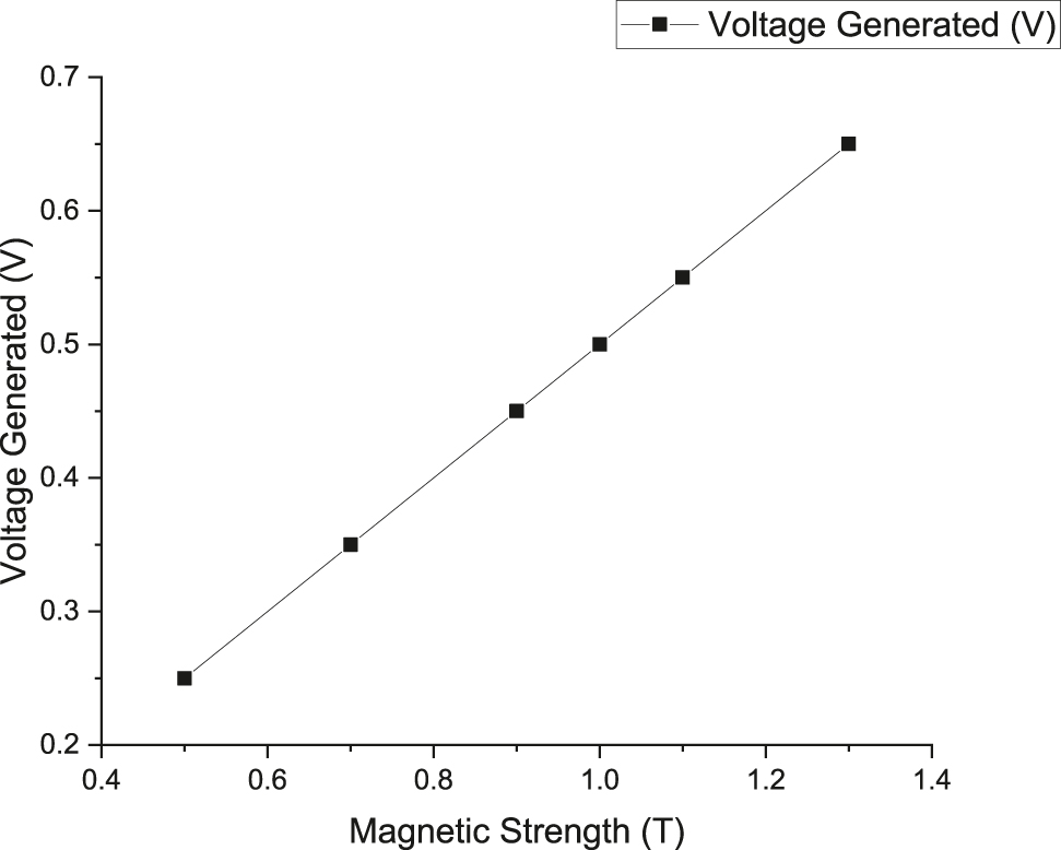
Parametric variations – magnetic strength V/s voltage.
Conclusion and future work
The LBEH is mathematically analyzed and designed in the FEM technique. The numerical simulations and the FEM simulations are carried out for the existing LBEH for the given design parameters. The simulations as obtained from the numerical and the FEM model indicates that the voltage developed is around 0.5 V for the frequency of 10 Hz. As the frequency varies, the voltage developed also decreases as reported in the conventional literature. The results obtained from both the numerical and the FEM analysis is well augmented with the theoretical concepts that are discussed and debated in the recent literature. At the end, a parametric analysis is also carried out in FEM for the designed LBEH and the same is verified using numerical simulations as well. Further improvements to the model can be carried out by optimizing the design of the energy harvester by using complex optimization techniques. The voltage developed can be varied using power electronic circuits as required.
-
Author contributions: All the authors have accepted responsibility for the entire content of this submitted manuscript and approved submission.
-
Research funding: None declared.
-
Conflict of interest statement: The authors declare no conflicts of interest regarding this article.
References
Bernal, A. A., and L. L. García. 2012. “The Modelling of an Electromagnetic Energy Harvesting Architecture.” Applied Mathematical Modelling 36 (10): 4728–41, https://doi.org/10.1016/j.apm.2011.12.007.Suche in Google Scholar
Cannarella, J., J. Selvaggi, S. Salon, J. Tichy, and D. A. Borca-Tasciuc. 2011. “Coupling Factor between the Magnetic and Mechanical Energy Domains in Electromagnetic Power Harvesting Applications.” IEEE Transactions on Magnetics 47 (8): 2076–80, https://doi.org/10.1109/tmag.2011.2122265.Suche in Google Scholar
Gros, I. C., D. C. Popa, P. D. Teodosescu, and M. M. Radulescu. 2017. “A Survey on Green Energy Harvesting Applications Using Linear Electric Generators.” In 2017 International Conference on Modern Power Systems (MPS), 1–5. IEEE.10.1109/MPS.2017.7974388Suche in Google Scholar
Guruacharya, S., and E. Hossain. 2017. “Self-Sustainability of Energy Harvesting Systems: Concept, Analysis, and Design.” IEEE Transactions on Green Communications and Networking 2 (1): 175–92.10.1109/TGCN.2017.2773565Suche in Google Scholar
Khaligh, A., P. Zeng, and C. Zheng. 2009. “Kinetic Energy Harvesting Using Piezoelectric and Electromagnetic Technologies—State of the Art.” IEEE Transactions on Industrial Electronics 57 (3): 850–60.10.1109/TIE.2009.2024652Suche in Google Scholar
Khan, F. U., and M. Iqbal. 2018. “Electromagnetic Bridge Energy Harvester Utilizing Bridge’s Vibrations and Ambient Wind for Wireless Sensor Node Application.” Journal of Sensors 2018: 1–9.10.1155/2018/3849683Suche in Google Scholar
Kulah, H., and K. Najafi. 2008. “Energy Scavenging from Low-Frequency Vibrations by Using Frequency Up-Conversion for Wireless Sensor Applications.” IEEE Sensors Journal 8 (3): 261–8, https://doi.org/10.1109/jsen.2008.917125.Suche in Google Scholar
Lee, B. C., and G. S. Chung. 2016. “Design and Analysis of a Pendulum-Based Electromagnetic Energy Harvester Using Anti-phase Motion.” IET Renewable Power Generation 10 (10): 1625–30, https://doi.org/10.1049/iet-rpg.2015.0396.Suche in Google Scholar
Li, C., S. Wu, P. C. K. Luk, M. Gu, and Z. Jiao. 2019. “Enhanced Bandwidth Nonlinear Resonance Electromagnetic Human Motion Energy Harvester Using Magnetic Springs and Ferrofluid.” IEEE/ASME Transactions on Mechatronics 24 (2): 710–7, https://doi.org/10.1109/tmech.2019.2898405.Suche in Google Scholar
Lin, T. R., J. Pan, P. J. O’Shea, and C. K. Mechefske. 2009. “A Study of Vibration and Vibration Control of Ship Structures.” Marine Structures 22 (4): 730–43, https://doi.org/10.1016/j.marstruc.2009.06.004.Suche in Google Scholar
Saha, C. R., T. O’donnell, N. Wang, and P. McCloskey. 2008. “Electromagnetic Generator for Harvesting Energy from Human Motion.” Sensors and Actuators A: Physical 147 (1): 248–53, https://doi.org/10.1016/j.sna.2008.03.008.Suche in Google Scholar
Sun, Q., S. Patil, S. Stoute, N. X. Sun, and B. Lehman. 2012. “Optimum Design of Magnetic Inductive Energy Harvester and its AC-DC Converter.” In 2012 IEEE Energy Conversion Congress and Exposition (ECCE), 394–400. IEEE.10.1109/ECCE.2012.6342795Suche in Google Scholar
Williams, C. B., and R. B. Yates. 1996. “Analysis of a Micro-electric Generator for Microsystems.” Sensors and Actuators A: Physical 52 (1-3): 8–11, https://doi.org/10.1016/0924-4247(96)80118-x.Suche in Google Scholar
Yen, B. C., and J. H. Lang. 2006. “A Variable-Capacitance Vibration-to-Electric Energy Harvester.” IEEE Transactions on Circuits and Systems I: Regular Papers 53 (2): 288–95, https://doi.org/10.1109/tcsi.2005.856043.Suche in Google Scholar
© 2022 Walter de Gruyter GmbH, Berlin/Boston
Artikel in diesem Heft
- Frontmatter
- Review
- A comprehensive review on electric vehicles: charging and control techniques, electric vehicle-grid integration
- Research Articles
- Evaluation of parameters influencing the performance of photovoltaic-thermoelectric (PV-TE) hybrid system
- Dispatchable power supply from beam down solar point concentrator coupled to thermal energy storage and a Stirling engine
- Modelling, design and parametric analysis of a levitation based energy harvester
- Performance optimization of flywheel using experimental design approach
- Assessment and optimization of photovoltaic systems at the University Ibn Tofail according to the new law on renewable energy in Morocco using HOMER Pro
- Optimizing hybrid power system at highest sustainability
- Preparation of Na2HPO4⋅12H2O-based composite PCM and its application in air insulated box
- The efficiency of linear electromagnetic vibration-based energy harvester at resistive, capacitive and inductive loads
- A numerical investigation of optimum angles for solar energy receivers in the eastern part of Algeria
- Experimental investigation of soiling effects on the photovoltaic modules energy generation
- Frequency domain analysis of a piezoelectric energy harvester with impedance matching network