
Effectiveness of line type and cross type piezoelectric patches on active vibration control of a flexible rectangular plate
-
Atul
 und
G. Divya Deepak
und
G. Divya Deepak

Abstract
In the present work, vibration control of a simply supported plate with line type and cross type piezoelectric (PZT) patches are investigated with and without actuation voltage. The plate is modeled under the assumption of Kirchhoff’s Plate theory. The mass of PZT patches remain constant in all cases. In case of actuation, applied voltage considered are 1, 2 and 3 mV. The external excitation to the plate is in the form of harmonically varying point load of 1 mN. It is noticed that cross type PZT patch is more effective in deflection suppression of plate than that of line type PZT patch at 3 mV of actuation at patch thickness of 0.75 μm. Suppression of central deflection of plate for line type and cross type PZT patches are obtained in different frequency bands of (175–185 Hz) and (870–880 Hz) respectively.
Introduction
In order to control structural vibrations, piezoelectric sensors and actuators can be easily bonded on the vibrating structure or embedded in it. Different kinds of control strategies are discussed for the design of a piezoactuated structure (Bisegna et al. 2000; Veley and Rao 1996). Zippo et al. (2015) proposed the Active vibration control of a free-edge rectangular sandwich plate where the control appears to be robust and efficient in reducing vibration in linear (small amplitude) and nonlinear (large amplitude) vibrations regimes, although the structure under investigation exhibits a relativity high modal density i.e., four resonances in a range of about 100 Hz. Lu, Wang, and Zhan (2017) demonstrated how the piezoelectric actuators actively control the lower modes (first bending and torsional modes) using modal controller, while the higher frequency vibration attenuated by viscoelastic passive damping layer. Abdeljaber, Avci, and Inman (2016) introduced a new intelligent methodology to mitigate the vibration response of flexible cantilever plates where it is observed that the neurocontroller reduces the vibration response of the flexible cantilever plate significantly; the results demonstrated the success and robustness of the neuro-controller independent of the type and distribution of the excitation force. Yue et al. (2017) proposed the control system which collects vibration signals from the piezoelectric sensors to identify location(s) of the largest vibration amplitudes and then select the best two from eight PVDF actuators to apply control forces so that the modal vibration suppression could be accomplished adaptively and effectively. Shivashankar and Kandagal (2016) showed the analytical model where transverse beam vibrations can be controlled by bonding resistively shunted piezoelectric to the beam’s surface. Several techniques were presented by Crawley and Anderson (ADINA 1997; Anderson and Crawley 1989) for modeling-induced strain actuation of beam and plate. They also performed static deflection test to verify their solution of strain results from experiment and finite element results. Yocum and Abramorich (2002) detailed the static experimental behavior of a cantilever beam actuated using piezo-ceramic patches. Topdar, Sheikh, and Dhang (2007) employed the finite element method (FEM) to study free vibrations of a piezoelectric coupled laminated plate under various boundary conditions. Liang and Batra (1997) investigated effects of thickness, mass density and stiffness of the piezoelectric layer on plate’s natural frequencies. The effect of electrical boundary conditions on major surfaces of piezoelectric layers was studied by Davis and Lesieutre (2000). Rofooei and Ali (2009) details the governing differential equation of motion for an undamped thin rectangular plate with a number of bonded piezoelectric patches on its surface and arbitrary boundary conditions is derived using Hamilton’s principle. Song, Sethi, and Li (2006) have introduced a wide range of applications of piezoceramic materials in vibration suppression of civil structures. In their work, the applicability of piezoceramic patches or stacks in controlling the response of relatively large cantilever beams, trusses, frames and cable-stayed structures were shown using some experimental studies. Sung (2002) has studied the active control of a simply supported Euler–Bernoulli beam under a moving mass using piezoelectric materials as actuators. Qiu et al. (2007) have investigated the application of piezoelectric ceramics as sensors and actuators for vibration suppression of a smart flexible clamped cantilever plate using analytical and experimental method.
In the proposed work, vibration control of a simply supported plate with line type and cross type piezoelectric (PZT) patches are investigated with and without actuation voltage. It is noticed that cross type PZT patch is more effective in deflection suppression of plate than that of line type PZT patch at 3 mV of actuation at patch thickness of 0.75 μm. The variations of thickness of piezoelectric patches on plate deflection in different frequency bands are also examined using finite element method. The two different PZT patches with the variation of thickness along with the actuation voltages are the main parameters in the proposed work.
Finite element formulation
Generalized Hamilton’s principle for a piezoelectric plate is given by (Crandall et al. 1968)
where,
T is total kinetic energy
U is total potential energy and
We is electrical energy are given as under
where,
[u] = vector of mechanical displacements
[S] = vector of mechanical strain
[T] = vector of mechanical stress
[D] = vector of electric displacements
[E] = vector of electric field
ρ = mass density of plate and piezoelectric patch
Vp = volume of piezoelectric patch
Vs = volume of plate
t = transpose of matrix
And subscripts p and s represents the piezoelectric patch and plate respectively.
If a set of discrete mechanical forces f is applied at location (xi, yi) and a set of discrete electric charge output q is extracted at locations (xj, yj), then the variation of the mechanically and electrically extracted work is given as (De Marqui, Erturk, and Inman 2009)
where,
nf = number of discrete mechanical forces
φj = scalar electrical potential
nq = number of discrete electrode pairs
The linear-elastic constitutive equation for plate is given as (De Marqui, Erturk, and Inman 2009)
and linear-electrostatic equation for piezoelectric material is given as (IEEE Group on Sonics and Ultrasonics 1978)
where,
c = elastic stiffness matrix
e = matrix of piezoelectric constants
ε = matrix of permittivity components
Now substituting both linear constitutive Eqs. (6) and (7) in Eq. (1), we get
Finite element modeling of piezoelectric plate
A four node rectangular finite element with three mechanical degrees of freedom per node as u, v, w in x, y and directions is used to model a plate with piezoelectric patch. The plate and piezoelectric patch is perfectly bonded to each other. Assuming piezoelectric patch is covered with conductive electrodes having one electrical degree of freedom. Thus, finite element of plate with patch has 13° of freedom. Based on Kirchhoff plate theory, transverse shear strains and rotary inertias of the finite element are neglected and in-plane displacement is assumed due to the bending of the plate only. The displacement field is, then given by (De Marqui, Erturk, and Inman 2009)
where, the displacement components u, v and w at a thickness level z from the neutral surface are given in terms of transverse displacement of the neutral surface.
The mechanical strain components under the assumption of linear-strain displacement can be given by
The transverse displacement of node k of rectangular finite element is assumed to vary in the polynomial form (Bathe 1996)
and bending rotations is given by
where P is polynomial terms which is given as
and the vector of generalized coordinates is
Considering four nodes per element and three degrees of freedom, the vector of nodal variables is given by
This can be expressed as
where A is a 12 × 12 transformation matrix (Erturk and Inman 2008) whose element are given by P and its derivatives through the definition of wk, θxk, θyk given in Eqs. (11)–(13).
The transverse deflection as a function of nodal variables then can be given by
where,
The vector of transverse displacement and cross-section rotations is related to the vector of nodal variables as
where,
Similarly, the vector of curvatures is given as
where,
Both Bη and Bk are 3 × 12 matrices.
The piezoelectric patch is poled in the thickness direction; the non-zero electric field component (which is assumed to be uniform in the thickness direction) can be expressed as
where the electric potential is assumed to be varying linearly across the electrode i.e., the electric field is assumed to be uniform in thickness directions. Then the electric field components is given by
where,
Based on Eq. (5), the element mass matrix m, stiffness matrix k, electromechanical coupling vector θ, capacitance cp and the mechanical forcing vector f can be expressed as
where,
Note that the mechanical damping matrix will be measured from the reference surface of the plate in the thickness direction (Beer and Johnston 1992; Erturk and Inman 2008). Here, it is assumed that both layers (plate and patch) have same mesh and the nodes are coincident.
Then the plane stress form of the constitutive equations for the piezoelectric patch can be expressed as
The elastic, piezoelectric and dielectric components of above Eq. (33) are given in contracted notations (i.e. Voigt’s notation) where 1, 2 and 3 directions are coincident with x, y and z directions.
Now, the global equations of motion are then obtained by assembling the element matrices given by Eqs. (27–31).
where,
[M] = global mass matrix
[K] = global stiffness matrix
{Ω} = global electromechanical coupling matrix
[Cp] = global capacitance matrix
[C] = global damping matrix
[F] = global vector of mechanical forces
[Q] = global vector of electric charge outputs
{v} = global vector of voltage outputs
Validation against the published results
For validation, published results of Ly et al. (2011) have been used. R. Ly has used piezoelectric cantilever beam having rectangular cross-section. The beam is subjected to 0.01 N excitation forces at the free end of cantilever. The length of beam considered is 49 mm having thickness 0.6 mm and width 3.8 mm respectively. Different proof mass at free end of the cantilever is used to adjust the resonant frequency to attain the required Eigen values. The result achieved by the present method is defined by Eq. (7).
Figure 1 shows the variation of Eigen values of first modes under different proof mass obtained by Ly et al. (2011) and present method. Figure 2 show the harmonic response in terms of tip displacement of piezoelectric cantilever beam without proof mass under excitation force of 0.01 N at tip and coefficient of damping assumed is 0.05.
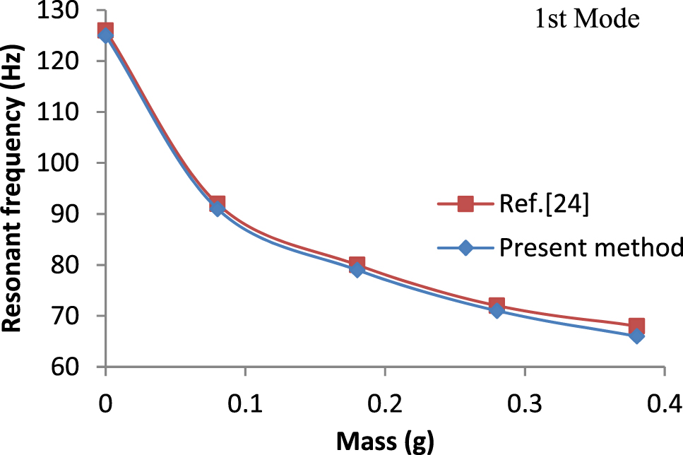
Variation of resonant frequencies with different proof mass.
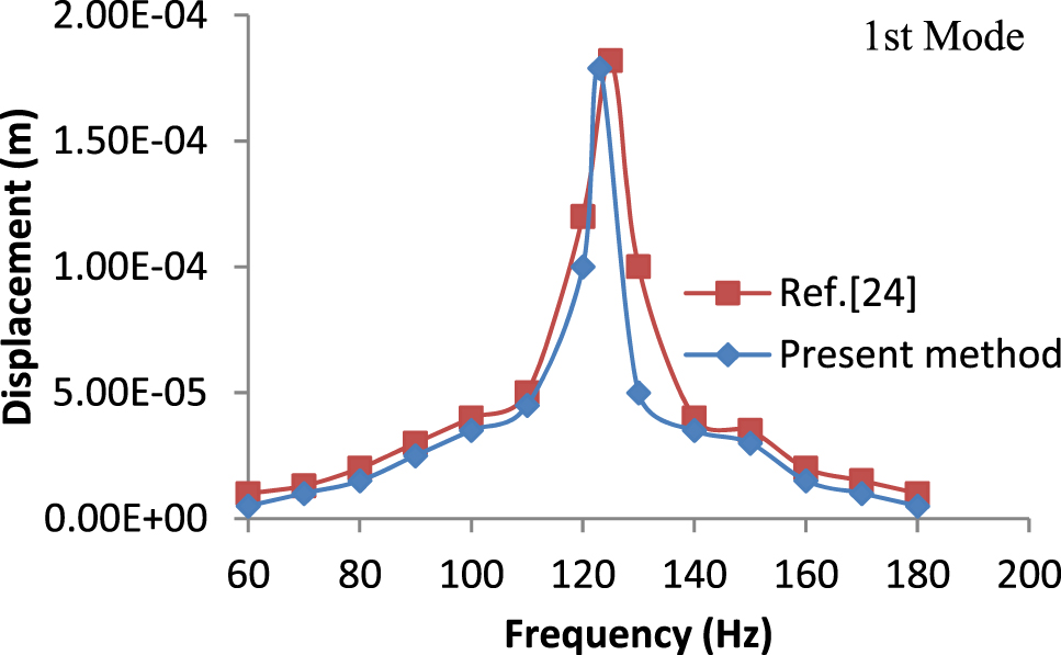
Variation of tip deflection with frequencies.
Figure 3 shows the variations of voltage generated by the piezoelectric cantilever beam for different proof mass. Results obtained by present finite element method closely match the published results by Ly et al. (2011). The present method refers that the plate is modeled according to the Kirchhoff’s Plate theory with the help Finite Element Method.
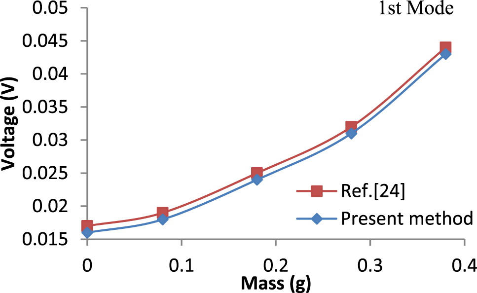
Variation of voltage generated with different proof mass.
Case studies
Two models of piezoelectric strip arrangement as shown in Figures 4 and 5 are used to investigate the vibration suppression behavior of plate with piezoelectric patches. The dimension of rectangular plate used is (5 × 5 × 0.3 μm). The following two models of piezoelectric (PZT) patch are:
Line type arrangement of PZT patch on a plate is shown in Figure 4
Cross type arrangement of PZT patch on a plate is shown in Figure 5
Plate with line type piezoelectric patch.
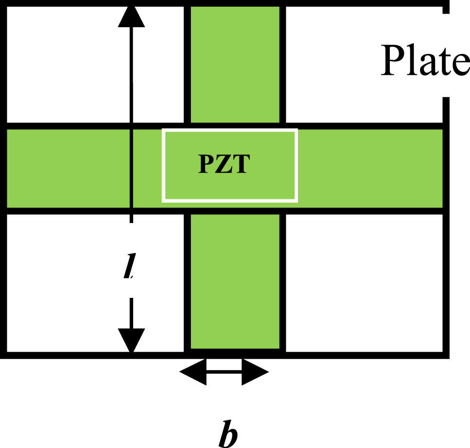
Plate with cross type piezoelectric patch.
Total mass of line type and cross type PZT patch is kept same. It was assumed that the plate is simply supported on all edges. On one side of plate, the layer of piezoelectric material is perfectly bonded. The thickness of piezoelectric patches vary while mass is kept constant for both the cases. Damping coefficient for the whole structure is assumed to be 0.0001. The material property of piezoelectric patch is of PZT-4. Different variations of the piezoelectric patch thickness are examined. The plate material considered is steel.
The linear-elastic constitutive equation for plate and linear-electrostatic equation for piezoelectric material is taken into account for description of plate with piezoelectric patch. And thus the finite element modeling for the Line type arrangement of PZT patches and Cross type arrangement of PZT patches on a plate are described by Eqs. (27)–(31). Here PZT-4 refers to the Lead Zirconate Titanate. The same methodology has been adopted for flexible rectangular plate which was used to validate the results for cantilever plate. As we know that the experimental results have been already validated with the Finite Element Method, so the simulation results are already verified accordingly.
Dynamic response analysis
The dynamic response of the plate with line type and cross type piezoelectric patch has been investigated with and without actuation voltage. In case of actuation, applied voltage considered are 1, 2 and 3 mV. The external excitation to the plate is in the form of harmonically varying point load of 1 mN at point 1 of the plate as shown in Figure 6. Transverse deflections are calculated at nine points numbered from 2 to 10 as shown in Figure 6. Transverse deflection at point 6 i.e., (Z6) gives central out of plane deflection. Average value of deflection for plate is calculated as:
where, Zavg is average deflection of plate.

Schematic diagram of plate.
Result and discussion
The following Tables 1–4 depicts the maximum central deflection (Z6) and average deflection (Zavg) of rectangular plate with line type and cross type PZT arrangement under different actuation voltage and without actuation voltage.
Central deflection (Z6) for line type PZT patch keeping mass constant.
| Thickness of patch (μm) | Deflection (without actuation) (μm) | Deflection (with actuation) (μm) | ||
|---|---|---|---|---|
| Actuation voltage | ||||
| 1 mV | 2 mV | 3 mV | ||
| 0.15 | 0.544 | 0.521 | 0.499 | 0.468 |
| 0.3 | 0.421 | 0.396 | 0.371 | 0.343 |
| 0.45 | 0.337 | 0.313 | 0.288 | 0.255 |
| 0.6 | 0.286 | 0.261 | 0.236 | 0.207 |
| 0.75 | 0.196 | 0.167 | 0.143 | 0.114 |
Average deflection (Zavg) for line type PZT patch keeping mass constant.
| Thickness of patch (μm) | Deflection (without actuation) (μm) | Deflection (with actuation) (μm) | ||
|---|---|---|---|---|
| Actuation voltage | ||||
| 1 mV | 2 mV | 3 mV | ||
| 0.15 | 0.538 | 0.501 | 0.474 | 0.443 |
| 0.3 | 0.414 | 0.367 | 0.351 | 0.321 |
| 0.45 | 0.329 | 0.284 | 0.259 | 0.236 |
| 0.6 | 0.276 | 0.238 | 0.213 | 0.184 |
| 0.75 | 0.188 | 0.151 | 0.128 | 0.103 |
Central deflection (Z6) for cross type PZT patch keeping mass constant.
| Thickness of patch (μm) | Deflection (without actuation) (μm) | Deflection (with actuation) (μm) | ||
|---|---|---|---|---|
| Actuation voltage | ||||
| 1 mV | 2 mV | 3 mV | ||
| 0.15 | 0.507 | 0.481 | 0.447 | 0.422 |
| 0.3 | 0.381 | 0.356 | 0.322 | 0.297 |
| 0.45 | 0.297 | 0.273 | 0.229 | 0.203 |
| 0.6 | 0.236 | 0.219 | 0.187 | 0.164 |
| 0.75 | 0.147 | 0.123 | 0.093 | 0.071 |
Average deflection (Zavg) for cross type PZT patch keeping mass constant.
| Thickness of patch (μm) | Deflection (without actuation) (μm) | Deflection (with actuation) (μm) | ||
|---|---|---|---|---|
| Actuation voltage | ||||
| 1 mV | 2 mV | 3 mV | ||
| 0.15 | 0.501 | 0.471 | 0.438 | 0.403 |
| 0.3 | 0.372 | 0.345 | 0.314 | 0.276 |
| 0.45 | 0.284 | 0.264 | 0.218 | 0.191 |
| 0.6 | 0.227 | 0.208 | 0.173 | 0.131 |
| 0.75 | 0.140 | 0.111 | 0.083 | 0.057 |
It is observed from Tables 1–4, that central deflection (Z6) and average deflection (Zavg) decrease with increase in thickness of PZT patch and actuation voltage for both the line type and cross type PZT patches. It is noteworthy that reduction in deflection is for cross type PZT patch. From Tables 1–4, the deflection before actuation and after actuation is unknown parameters. And the thickness of PZT patches and applied voltage is known parameters.
Figures 7 and 8 shows the variation of central deflection (Z6) of plate with line type and cross type PZT patches for different frequencies for a given PZT thickness equal to 0.15 μm. It is observed from Figure 7 that maximum suppression of deflection is obtained at 180 Hz at 3 mV of actuation for line type PZT patch. For line type PZT patch, increase of actuation voltage is effective for suppression of central deflection (Z6) in a limited frequency range of (175–185 Hz) approximately. Similarly, from Figure 8 it is noticed that maximum suppression of deflection for cross type PZT patch is obtained at 876 Hz with 3 mV of actuation. For cross type PZT patch, increase of actuation voltage is effective for suppression of deflection in a limited frequency range of (870–880 Hz) approximately. It is noteworthy that with cross type PZT arrangement, effective frequency band for maximum suppression of deflection is shifted from lower frequency band to higher frequency band.
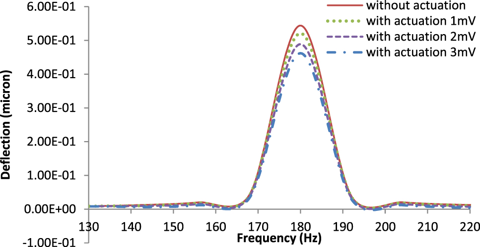
Variation of central deflection (Z6) with frequency for plate with line type PZT patch.
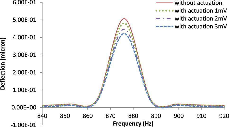
Variation of central deflection (Z6) with frequency for plate with cross type PZT patch.
Figures 9 and 10 shows 3D graph for the thickness of the PZT patches versus deflection with and without actuation voltage. It has been observed that with the increase in thickness of PZT patches without actuation voltage the deflection control for the flexible plate get reduced. Further with the variation of PZT patch thickness along with actuation voltage of 3 mV the deflection of flexible plate can be controlled more. The graphical illustration of input and output signals (before and after actuations) in time domain is shown in Figures 7 and 8.
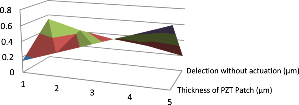
Central deflection (Z6) for line type PZT patch without actuation in 3D.
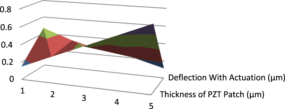
Central deflection (Z6) for line type PZT patch with actuation (3 mV) in 3D.
Conclusions
The active vibration control of the plate under harmonic excitation can be achieved for a particular frequency range by application of piezoelectric patches.
Cross type PZT patch arrangement is more effective in deflection control of plate than that of line type PZT patch in all cases at 3 mV of actuation at patch thickness of 0.75 μm.
Vibration control of central deflection for line type and cross type PZT patches are obtained in different frequency bands of (175–180 Hz) and (870–880 Hz) respectively.
The proposed work helps in optimal placements of piezoelectric patch for maximizing the vibration control and based on LQR control strategy for sensors and actuators placement.
-
Author contributions: All the authors have accepted responsibility for the entire content of this submitted manuscript and approved submission.
-
Research funding: None declared.
-
Conflict of interest statement: The authors declare no conflicts of interest regarding this article.
References
Abdeljaber, O., O. Avci, and D. J. Inman. 2016. “Active Vibration Control of Flexible Cantilever Plates Using Piezoelectric Materials and Artificial Neural Networks.” Journal of Sound and Vibration 363: 33–53, https://doi.org/10.1016/j.jsv.2015.10.029.Suche in Google Scholar
ADINA. 1997. Verification Manual Report ARD97-9, 219–36. Water-Town: ADINA R d D Inc.Suche in Google Scholar
Anderson, E. H., and E. F. Crawley. 1989. Piezoceramic Actuation of One- and Two-Dimensional Structures, 95–117. Cambridge: Space Systems Laboratory SSL 5-89, Mas-sachusetts Institute of Technology.Suche in Google Scholar
Bathe, K.-J. 1996. Finite Element Procedures. Englewood Cliffs: Prentice-Hall.Suche in Google Scholar
Beer, F. P., and E. R. JohnstonJr. 1992. Mechanics of Materials. New York: McGraw-Hill.Suche in Google Scholar
Bisegna, P., G. Caruso, D. Del Vescovo, S. Galeani, and L. Menini. 2000. “Semi-Active Control of a Thin Piezoactuated Structure.” In Proceedings of SPIEs 7th International Symposium, Vol. 3989, 300–11. Newport Beach: Hupper Hyde.Suche in Google Scholar
Crandall, S. H., D. C. Karnopp, E. F. KurtzJr., and D. C. Pridmore-Brown. 1968. Dynamics of Mechanical and Electromechanical Systems. New York: McGraw-Hill.Suche in Google Scholar
Davis, C. L., and G. A. Lesieutre. 2000. “An Actively Tuned Solid-State Vibration Absorber Using Capacitive Shunting of Piezoelectric Stiffness.” Journal of Sound and Vibration 232 (3): 601–17, https://doi.org/10.1006/jsvi.1999.2755.Suche in Google Scholar
De MarquiJr.C., A. Erturk, and D. J. Inman. 2009. “An Electromechanical Finite Element Model for Piezoelectric Energy Harvester Plates.” Journal of Sound and Vibration 327: 9–25, https://doi.org/10.1016/j.jsv.2009.05.015.Suche in Google Scholar
Erturk, A., and D. J. Inman. 2008. “A Distributed Parameter Electromechanical Model for Cantilevered Piezoelectric Energy Harvesters.” ASME Journal of Vibration and Acoustics 130: 041002 (15pp)., https://doi.org/10.1115/1.2890402.Suche in Google Scholar
IEEE Group on Sonics and Ultrasonics. 1978. IEEE Standard on Piezoelectricity. New York: IEEE.Suche in Google Scholar
Liang, X. Q., and R. C. Batra. 1997. “Changes in Frequencies of a Laminated Plate Caused by Embedded Piezoelectric Layers.” AIAA Journal 35: 1672–3, https://doi.org/10.2514/3.13728.Suche in Google Scholar
Lu, J., P. Wang, and Z. Zhan. 2017. “Active Vibration Control of Thin-Plate Structures with Partial SCLD Treatment.” Mechanical Systems and Signal Processing 84: 531–50, https://doi.org/10.1016/j.ymssp.2016.06.013.Suche in Google Scholar
Ly, R., M. Rguiti, S. D’Astorg, A. Hajjaji, C. Courtois, and A. Leriche. 2011. “Modeling and Characterization of Piezoelectric Cantilever Bending Sensor Forenergy Harvesting.” Sensors and Actuators A168: 95–100, https://doi.org/10.1016/j.sna.2011.04.020.Suche in Google Scholar
Qiu, Z., X. Zhang, H. Wu, and H. Zhang. 2007. “Optimal Placement and Active Vibration Control for Piezoelectric Smart Flexible Cantilever Plate.” Journal of Sound and Vibration 301 (3–5): 521–43, https://doi.org/10.1016/j.jsv.2006.10.018.Suche in Google Scholar
Rofooei, F. R., and N. Ali. 2009. “Application of Active Piezoelectric Patches in Controlling the Dynamic Response of a Thin Rectangular Plate Under a Moving Mass.” International Journal of Solids and Structures, International Journal of Solids and Structures 46: 2429–43, https://doi.org/10.1016/j.ijsolstr.2009.01.034.Suche in Google Scholar
Shivashankar, P., and S. B. Kandagal. 2016. “Analytical Modeling and Optimal Resistance Estimation in Vibration Control of Beams with Resistively Shunted Piezoelectrics.” International Journal of Mechanical Sciences 119: 310–9, https://doi.org/10.1016/j.ijmecsci.2016.10.026.Suche in Google Scholar
Song, G., V. Sethi, and H.-N. Li. 2006. “Vibration Control of Civil Structures Using Piezoceramic Smart Materials: A Review Paper.” Engineering Structures 28: 1513–24, https://doi.org/10.1016/j.engstruct.2006.02.002.Suche in Google Scholar
Sung, Y.-G. 2002. “Modeling and Control with Piezoactuators for a Simply Supported Beam Under a Moving Mass.” Journal of Sound and Vibration 250 (4): 617–26, https://doi.org/10.1006/jsvi.2001.3941.Suche in Google Scholar
Topdar, P., A. H. Sheikh, and N. Dhang. 2007. “Vibration Characteristics of Composite/Sandwich Laminates with Piezoelectric Layers Using a Refined Hybrid Plate Model.” International Journal of Mechanical Sciences 49: 1193–203, https://doi.org/10.1016/j.ijmecsci.2007.04.001.Suche in Google Scholar
Veley, P. E., and S. S. Rao. 1996. “A Comparison of Active, Passive and Hybrid Damping in Structural Design.” Smart Materials and Structures 5: 660–71, https://doi.org/10.1088/0964-1726/5/5/014.Suche in Google Scholar
Yocum, M., and H. Abramorich. 2002. “Static Behavior of Piezoelectric Actuated Bearms.” Computers & Structures 80: 1797–808, https://doi.org/10.1016/s0045-7949(02)00206-7.Suche in Google Scholar
Yue, H., Y. Lu, Z. Deng, and H. Tzou. 2017. “Experiments on Vibration Control of a Piezoelectric Laminated Paraboloidal Shell.” Mechanical Systems and Signal Processing 82: 279–95, https://doi.org/10.1016/j.ymssp.2016.05.023.Suche in Google Scholar
Zippo, A., G. Ferrari, M. Amabili, M. Barbieri, and F. Pellicano. 2015. “Active Vibration Control of a Composite Sandwich Plate.” Composite Structures 128: 100–14, https://doi.org/10.1016/j.compstruct.2015.03.037.Suche in Google Scholar
© 2021 Walter de Gruyter GmbH, Berlin/Boston
Artikel in diesem Heft
- Frontmatter
- Research Articles
- Optimized routing with efficient energy transmission using Seline Trustworthy optimization for waste management in the smart cities
- Effectiveness of line type and cross type piezoelectric patches on active vibration control of a flexible rectangular plate
- Energy visibility of a modeled photovoltaic/diesel generator set connected to the grid
- Techno-economic analysis and design of hybrid renewable energy microgrid for rural electrification
- The comparison of triboelectric power generated by electron-donating polymers KAPTON and PDMS in contact with PET polymer
- Investigation of aerodynamic interaction between the balloon and the ducted wind turbine in airborne configuration
- Experimental investigation on treated transformer oil (TTO) and its diesel blends in the diesel engine
- Frequency response locking of electromagnetic vibration-based energy harvesters using a switch with tuned duty cycle
- Evaluation of energy generation in Iraqi territory by solar photovoltaic power plants with a capacity of 20 MW
- Review
- Quantitative analysis of DC–DC converter models: a statistical perspective based on solar photovoltaic power storage