Corrosion of stainless steels and corrosion protection strategies in the semiconductor manufacturing industry: a review
-
Chaoran Ma
Chaoran Ma received his M.Sc. Degree in Materials Science and Engineering in 2019 from China University of Petroleum. He is currently a Ph.D. student at Northeastern University, China. His research focuses on the corrosion and protection of stainless steel in semiconductor manufacturing industry. His area of expertise includes design of experiments, EIS, thermodynamic calculation. He has several journal publications and received some awards about corrosion.
Peng Zhou is a lecturer at Northeastern University, China. He obtained his Ph.D. in Materials Engineering from Pierre and Marie Curie University, France. His research focuses on design of corrosion-resistant magnesium alloy, chemical conversion film for magnesium alloy, passivation technology for stainless steel, rolling technology for stainless steel. He has published several high impact journals and received a lot of awards during his academic life.
 ,
Yang Zhao
,
Yang Zhao
Yang Zhao is currently an associate professor at Northeastern University, China. He obtained his Ph.D. in Materials Engineering from Harbin Engineering University, China. His research focuses on the corrosion of stainless steel in the petroleum industry. His area of expertise includes lifetime prediction, thermodynamic calculations, simulation, programming, surface modification. He has published several high-impact refereed journals and attended many conferences.
Tao Zhang is a professor and doctoral supervisor at Northeastern University, China. He obtained his Ph.D. from Institute of Metals, Chinese Academy of Sciences. His research areas include surface treatment technologies for magnesium alloys, corrosion and protection in the petroleum industry, and corrosion and protection in high-precision microchip manufacture. He has published 90 high-level scientific papers, 15 national invention patents, and 1 monograph.
Fuhui Wang is the chairman of the ninth and tenth sessions of the Council of the Chinese Society for Corrosion and Protection, and the director of the High Temperature Professional Committee. He is a professor and doctoral supervisor at Northeastern University, China. His research areas include the chemical stability of nanomaterials, high-temperature corrosion and protection of advanced materials, and surface modification of materials. He has published more than 350 papers in influential academic journals and conferences, with over 3000 citations and over 30 invention patents.

Abstract
Stainless steels are used extensively in semiconductor manufacturing as chamber, structure component and gas delivery systems. The corrosion in the aggressive gas in the semiconductor manufacturing industry leads to particle release, contaminating wafers and limiting their application. Moisture content can accelerate the corrosion rate of stainless steel. In a high-temperature environment, the corrosion is determined by the synergistic effect of the vapour of the corrosion product and thermal ageing. To eliminate corrosion, lots of efforts have been performed and categorized into three aspects: (1) Material purification using innovating metallurgy techniques, especially vacuum induction melting (VIM) and vacuum arc remelting (VAR). The ultra-pure stainless steel minimizes the inclusion in stainless steel, suppressing the breakdown of the passive film. (2) Smoothing the surface by polishing; the polishing surface shows hydrophobic behaviour and decreases moisture absorption. (3) Applying surface and coating techniques against corrosion, including passivation treatment and electroplating/electroless Ni-based coating. Herein, the techniques mentioned above are reviewed, and the prospect and development of stainless steel in the semiconductor manufacturing industry are forecasted.
1 Introduction
A bottleneck plaguing the semiconductor manufacturing industry has been cleanliness. Particularly, the gas purity requirements in the semiconductor manufacturing industry are even more stringent, and to effectively improve the technological level, the particle and chemical impurity content of wafer processing technology must be strictly regulated. Contamination in semiconductor generation come from various sources, including bare silicon wafer surfaces, wet chemicals, process equipment, and gas delivery system (Krishnan and Laparra 1997). The main contaminating impurities negatively impacting process efficiency are moisture, trace gases, particles, and metals.
Nowadays, stainless steel is widely applied in semiconductor manufacturing industries, concentrating on gas delivery systems and mainly undertaking electronic special gas delivery and distribution work (Kadonaga 1992; Miyazaki et al. 1996; Ohmi et al. 1998; Savadkouhi 2003; Xing et al. 2022). High-purity electronic special gases, such as HCl, HBr, HF, HI, SiH4, CF4 and NH3, are used in the semiconductor manufacturing industry for numerous processes, such as wafer etching and vapour phase epitaxy. In addition, vacuum pumps cannot completely remove moisture adsorption in a high vacuum environment. Although the residual moisture is extremely low (ppb – ppm level), it is not negligible in the semiconductor manufacturing industry. Stainless steel is characterised by high process accuracy, high surface finish and excellent flexibility, offering outstanding advantages of processability and cleanliness. However, corrosion products are produced after prolonged exposure to stainless steel with electronic special gases. The particles generated by the corrosion are entrained in the gaseous fluid, causing contamination of the processing system (Accomazzo and Grant 1989; Laly et al. 1996).
Stainless steel has also been used in gas filters (Amari et al. 1999; Haider and Shadman 1989), mass flow controllers (Ahn et al. 2008; Hirata and Esashi 2002) and valve diaphragms (Kumagai 1990; Yamaji et al. 2013), important components of the gas delivery system. Gas filters purify electronic special gases by filtering out particles to ensure high gas cleanliness. Mass flow controllers and diaphragm valves ensure effective and precise control of special gas flow. In addition to the gas delivery system, some structural components in the chamber also comprise stainless steel, providing excellent structural support (Berg 2014; Nemanic and Setina 2000; Sefa et al. 2017). The gas pipeline, mass flow controller, diaphragm valve and gas filter at ambient or low temperature under high vacuum are all in service, except for the delivery pipeline at the cylinder end with approximately 0.6 MPa pressure. Additionally, the chambers’ structural components work well at high temperatures under vacuum. Due to the prolonged direct exposure of stainless steel to electronic special gases, ensuring the corrosion resistance of stainless steel is crucial to maintaining a high purity level throughout the system.
However, stainless steel’s corrosion mechanisms in different service environments are distinct, requiring priority to elucidate the corrosion mechanisms in different environments and develop targeted corrosion protection solutions. Common grades and service conditions for stainless steel in the semiconductor manufacturing industry are given in Table 1 (Amari et al. 1999; Ahn et al. 2008; Sefa et al. 2017; Yamaji et al. 2013).
Applications of stainless steel in the semiconductor manufacturing industry.
| Serial no. | Material grade | Components | Process technology |
|---|---|---|---|
| 1 | 316LVV | Gas input piping, exhaust gas output piping | ICP, CCP, PECVD, ISSG, DPN |
| 2 | 316L | Hinge assembly, structural components, inner core of gas filters, valve diaphragms, etc. | ISSG, DPN, EPI |
| 3 | 304 | Equipment framework | ICP, CCP, PECVD, ISSG, DPN |
| … | … | … | … |
-
ICP, inductive coupled plasma; CCP, capacitively coupled plasma; PECVD, plasma enhanced chemical vapour deposition; EPI, epitaxial growth; ISSG, in-situ steam generation; DPN, decoupled plasma nitridation.
This study reviews the corrosion mechanisms of stainless steel at ambient temperature and high-temperature vacuum. Then, the anti-corrosion methods, including material purification, polishing and surface and coating techniques are introduced. Finally, the prospect and future directions are discussed.
2 Corrosion mechanisms of stainless steel in semiconductor manufacturing industry
Depending on temperature conditions, the corrosive environment in the semiconductor manufacturing industry can be divided into ambient and high temperatures. In ambient environments, stainless steel is mainly applied in gas delivery systems, including gas piping, diaphragm valves, mass flow controllers and gas filters. While at high temperatures, stainless steel is mainly applied for chambers’ internal structural components.
Pure corrosive gases sluggishly attack stainless steel, yet some factors can accelerate the corrosion rate. Crucially, the corrosion mechanisms’ acceleration is significantly distinct under different temperature environments. Highly corrosive gases are extremely sensitive to moisture for the gas delivery system at ambient temperatures. Therefore, moisture can significantly accelerate the corrosion rate and release product particles. Prolonged high-temperature service can cause thermal ageing of stainless steel for chamber structural components in high-temperature environments, significantly reducing corrosion resistance. Therefore, thermal ageing can significantly accelerate the corrosion rate and release product particles.
2.1 Corrosion mechanisms in the gas delivery system at ambient temperatures
The gas delivery system is divided into gas cylinders, gas pipelines, valve manifold boxes, gas filters, mass flow controllers, diaphragm valves and other equipment. Some gas cylinders, valve diaphragms, gas pipeline materials, filter screens and other related components are stainless steel. In the semiconductor manufacturing industry, gas pipelines are mainly made of 316LVV after electrolytic polishing (EP) (Krishnan and Laparra 1997), while gas cylinders, valve diaphragms, and filter components are composed of 316L after EP (Amari et al. 1999; Ahn et al. 2008; Yamaji et al. 2013). 316LVV is the high-purity 316L stainless steel after VIM and VAR refinement. 316L has a composition per ASTM A 269 and ASTM A 632, except for limited sulphur (0.012 %). Additional composition requirements for 316LVV are shown in Table 2.
Additional composition requirements for 316LVV.
| Element | C | S | Mn | Cu | Nb | Al | Ca | Ti | Se |
|---|---|---|---|---|---|---|---|---|---|
| Range-wt% (max) | 0.030 | 0.010 | 1.5 | 0.30 | 0.05 | 0.01 | 0.02 | 0.02 | 0.02 |
Prolonged contact with electronic special gases at room or low temperatures (<100 °C) are the service conditions for stainless steel. HCl, HBr, HI and HF are aggressive to stainless steel with a high sensitivity to moisture content. The trace amounts of moisture can significantly accelerate the stainless steel corrosion. Subsequently, the corrosion products enter the high-purity gas as particles, causing contamination and affecting the wafer quality (Accomazzo and Grant 1989; Laly et al. 1996). Therefore, investigating the moisture behaviour in the semiconductor manufacturing industry is a priority to reveal the corrosion mechanisms of stainless steel in ambient environments.
2.1.1 Moisture adsorption on material surfaces
When the equipment is in contact with the atmosphere, moisture, impurities, and gas molecules are adsorbed on its surface (Figure 1) (Saito 1997). Before the semiconductor process, the chambers and pipelines are pumped down to ensure a vacuum inside the equipment. The pumping process can be divided into the following stages: (1) A vacuum pump expels the air inside the equipment. (2) Some gases are adsorbed on the surface at atmospheric pressure and then slowly desorbed under vacuum. H2O dominates the process, and the desorption rate depends on various gases’ surface binding energy, temperature, and surface coverage. (3) Some gases are dissolved in the material during manufacturing and slowly diffused in a vacuum. The process is mainly H2, and the emission rate depends on material properties, temperature, gas solubility and diffusion rate. (4) Extremely small amounts of gas can penetrate the vacuum chamber walls and enter the chamber. The emission rate depends on the material’s properties and the chamber walls’ thickness (Weston 1975).
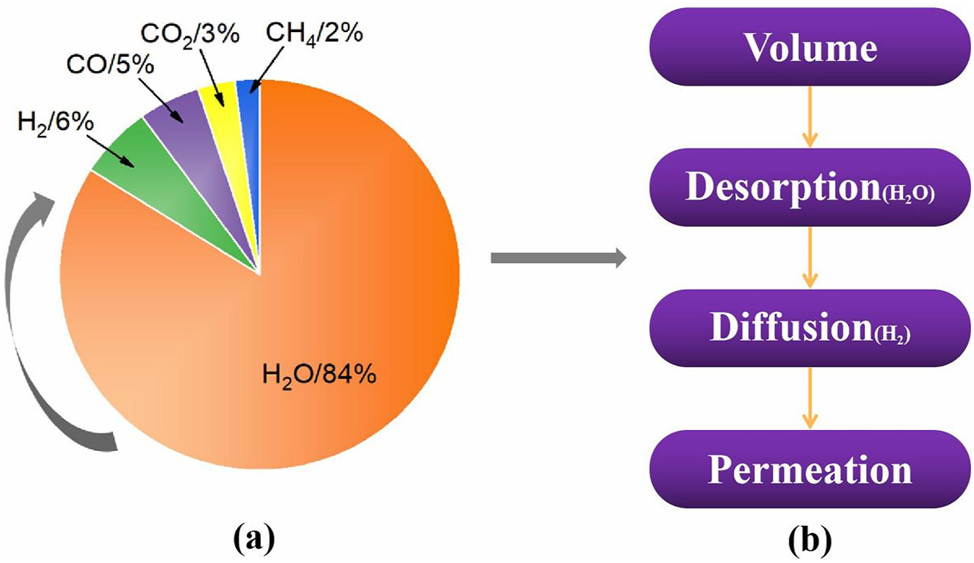
Vacuum systems of semiconductor manufacturing industry. (a) Percentage of vacuum system gas types; (b) sequence of pumping.
Figure 1 shows that moisture is a major component of pumping down and is not easily dislodged by desorption on the material’s surface. Most high-purity corrosion gases (such as HCl, HBr, etc.) must overcome the bond energy to react with stainless steel; therefore, the corrosion rate is small. However, when the moisture adsorption is large on the stainless steel surface, some corrosion gases dissolve, and electrochemical corrosion occurs (Fine et al. 1995; Lequien and Moine 2021). Therefore, moisture can significantly contribute to stainless steel corrosion. Therefore, moisture adsorption and desorption on the material surface is a condition that must be considered in the gas delivery system.
The moisture adsorption can be physical and chemical. Physical adsorption occurs under van der Waals forces between the molecules’ surface, while chemical adsorption involves the chemical bonding of molecules to surface atoms. When sufficient energy is obtained, the adsorbed molecule desorbs under vacuum, called the adsorption energy. Under ideal conditions, the adsorption energy (desorption activation energy) is a single value. However, the adsorption energy is not a single value since the adsorption state is complex due to material surface roughness, surface chemistry, etc. (Figure 2). Molecules with adsorption energy below 100 kJ/mol desorb rapidly at room temperature (Saito 1997).
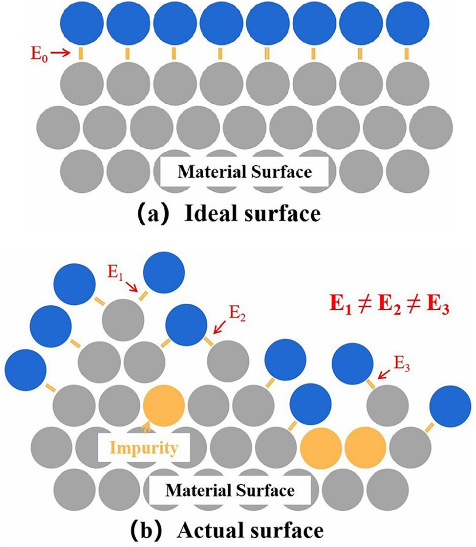
Moisture adsorption model: (a) ideal surface, (b) actual surface.
The moisture adsorption capacity is affected by various factors, including partial pressure, surface properties of the specimen and the gas flow rate containing moisture. Siefering and Whitlock (1994) reported that the moisture adsorption capacity is significantly related to the moisture partial pressure. Under constant ambient pressure, the partial pressure of moisture changes by varying the moisture concentration, and experimental results are shown in Figure 3.
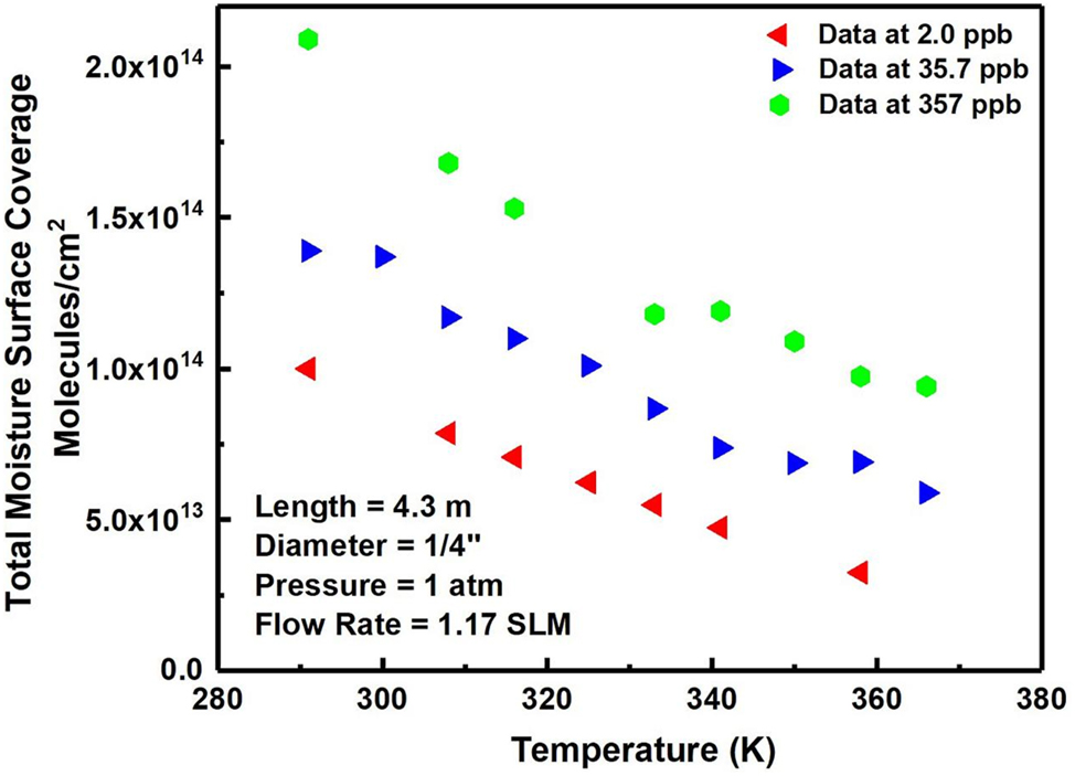
Isobaric adsorption lines for moisture molecules at different temperatures and partial pressures (Siefering and Whitlock 1994). Reprinted with permission; copyright 1994 American Vacuum Society.
More moisture is absorbed on the material’s surface when the partial pressure of moisture is high and the temperature is lower. The surface moisture coverage of the material was 2.2 × 10¹⁴ mol/cm2 at a moisture concentration of 357 ppb and a temperature of 273.15 K (Figure 3). At this point, it is sub-monolayer adsorption, where multiple adsorption layers exist on stainless steel surfaces (EP) at higher partial pressures. For example, seven monolayers of moisture are formed on stainless steel surfaces at a moisture concentration of 100 ppm in argon (Siefering and Whitlock 1994).
Siefering proposed a semi-empirical model of the Langmuir relationship to fit the results obtained with the following equation.
where
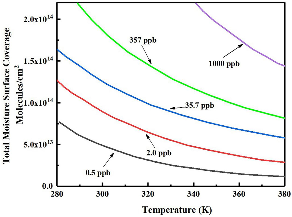
Semi-empirical model fitting lines for moisture molecules at different temperatures and partial pressures (Siefering and Whitlock 1994). Reprinted with permission; copyright 1994 American Vacuum Society.
Surface properties, including roughness, treatment processes and chemistry, significantly impact moisture adsorption. Dylla et al. (1993) found that the gas emission rate increased with the surface roughness factor (the ratio of true surface area to geometric surface area), i.e. the content of adsorbed moisture molecules increased, attributed to the increased number of adsorption sites on moisture molecules.
Tsuji et al. (2017) described the moisture adsorption process on the pipe’s inner wall and calculated the amount of moisture adsorption by integral calculation. Figure 5 shows a delay time between the moisture-injected and outflowed sides. This is the time required for the moisture adsorbed on a specimen surface to reach saturation. The amount of moisture adsorption is related to the surface state of different materials during this time interval.
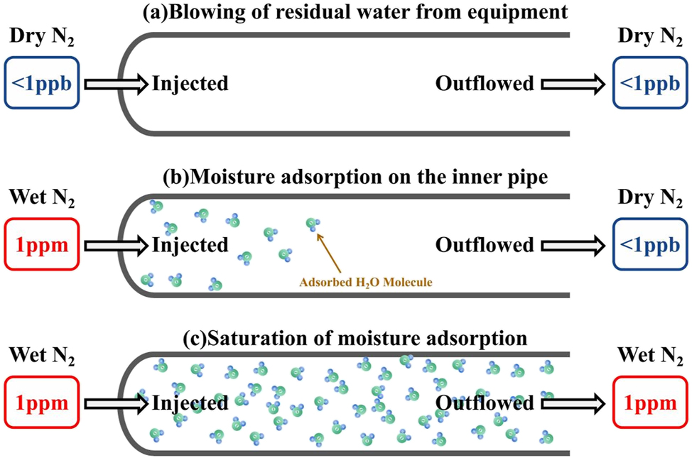
Schematic diagram of the moisture delay adsorption process (Tsuji et al. 2017). Reprinted with permission; copyright 2017 Japan Society of Applied Physics.
After different surface treatments, the initial phase exhibits the same adsorption rate, as shown in Figure 6. The final stage of moisture adsorption significantly differs due to the surface properties, i.e. the smoother surface properties absorb less moisture.
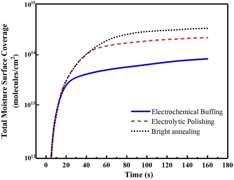
Moisture adsorption capacity of different surfaces (Tsuji et al. 2017). Reprinted with permission; copyright 2017 Japan Society of Applied Physics.
2.1.2 Moisture condensation in the corrosive gases
When the stainless steel surface is exposed to atmospheric or residual moisture from various valves, moisture adsorption is inevitable. Moisture condensation occurs under certain conditions on the surface as moisture adsorption reaches a critical value.
There is a correlation between the moisture molecules’ condensation on the surface and the dew point temperature of the gas mixture (Tsuji et al. 2017). Moisture condensation occurs once the dew point temperature is above the ambient temperature. Conversely, the moisture molecules remain in a gaseous state. The dew point temperature is calculated from the moisture partial pressure by the following equation (Kiang 1981);
where
When the dew point temperature of the gas mixture drops, moisture condenses on the surface after mixing with HCl, HBr, HF, etc. The equation to calculate the dew point temperature for different gases is as follows (Kiang 1981);
where T is the dew point temperature (K),
For ideal gaseous conditions, the partial pressure and concentration are converted. Therefore, plotting moisture concentration versus dew point temperature for different gaseous environments is feasible.
Significant differences exist between dew point temperatures of different gases at ambient temperature. Corrosive gases can significantly increase the dew point temperature of a gas mixture. The higher the dew point temperature, the greater the condensation tendency for moisture. HBr, HCl, and HF gases can significantly increase the condensation tendency of moisture, with HBr being the greatest (Figure 7).
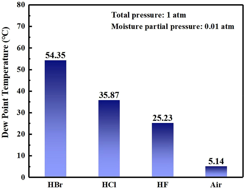
Dew point temperatures of different gas mixtures at an total pressure of 1 atm and moisture partial pressure of 0.01 atm.
In the gas delivery system, there are cases of replacement cylinders, maintenance pipelines and damaged valves, resulting in contact between the inner surface of the gas pipelines and the atmosphere. The moisture in the gas condenses on the material surface, when the temperature is different between the material surface and the gas mixture. Figure 8 depicts that a tiny amount of moisture is mixed with HBr upon introducing high-pressure HBr, forming a high-propensity gas mixture for moisture condensation, resulting in secondary condensation in the gas delivery system.
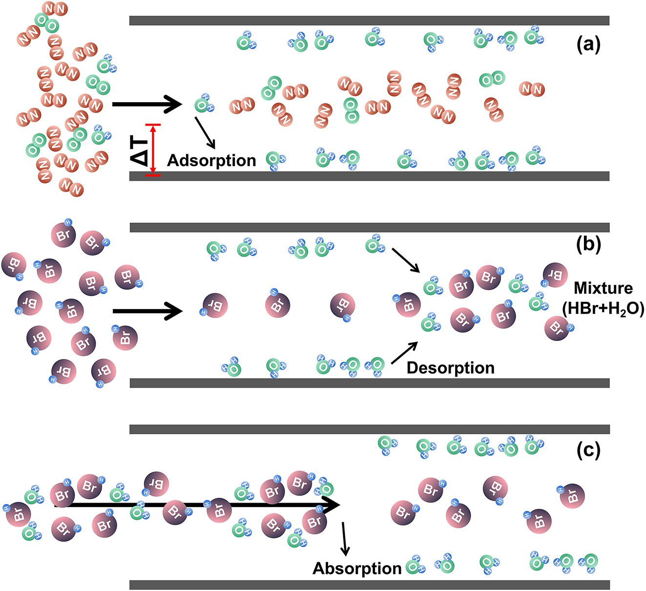
The adsorption behaviour of moisture in gas delivery system.
2.1.3 Corrosion mechanism of moisture interaction with stainless steel
Lange’s Handbook of chemistry suggests that corrosion gases have extremely large solubility in moisture. Corrosive gases have a high propensity to dissolve in moisture (Fine et al. 1995). Many corrosive gases are dissolved in the condensate moisture, forming a supersaturated acidic solution, generating electrochemical effects to accelerate the corrosion reaction. Thus, the corrosion products in the form of particles contaminate high-purity gas, reducing the wafer quality.
Taking an H2O and HCl mixture as an example, water molecules are adsorbed on the stainless steel surface as a monolayer. The water molecules condense when the dew point temperature is higher than the ambient temperature, gradually forming a precursor film (Figure 9a). As moisture condensation proceeds, droplets tend to form at depressions, defects or inclusions (Tsuji et al. 2017). Due to the high affinity of HCl gas for water, it dissolves into droplets, forming a supersaturated acidic and a chloride ion concentrated electrolyte (Figure 9b), inducing a rapidly developing droplet corrosion (Figure 9c). In addition, a certain amount of gas is dissolved into the precursor film, causing certain corrosion on the material’s surface. The droplet volume gradually increases as the water molecules condense, while the film thickens, prompting the metal ions dissolution and accelerating the corrosion rate (Figure 9d). Under the influence of gravity and gaseous fluids, condensation droplets move and stagnate along the specimen, thus, accelerating the corrosion reactions. The high-purity gas is contaminated. When HCl concentration in the condensed droplets increases, the surface tension gradually decreases, flattening the condensed droplets. In the presence of high water content, it may continuously concentrate the solutes in the precursor film on the material surface over time, gradually evolving into a thin liquid film morphology (Figure 9f) (Askey et al. 1993; Lequien and Moine 2021; Mizushima 2007; Weissenborn and Pugh 1996).
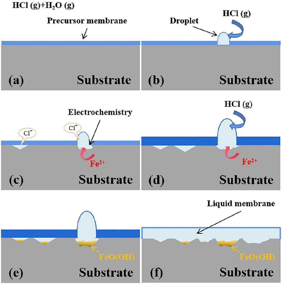
Corrosion mechanism of H2O and HCl gas mixtures.
Lequien and Moine (2021) proposed that the corrosion morphology can be significantly altered by intermingling moisture with the HCl gas. A distinct droplet corrosion pattern characterises the initial stage of corrosion, and traces of micro-droplet formation can be observed. The droplet corrosion morphology disappears and transforms into a liquid membrane-covered corrosion morphology (Figure 10). The above corrosion mechanism was verified.
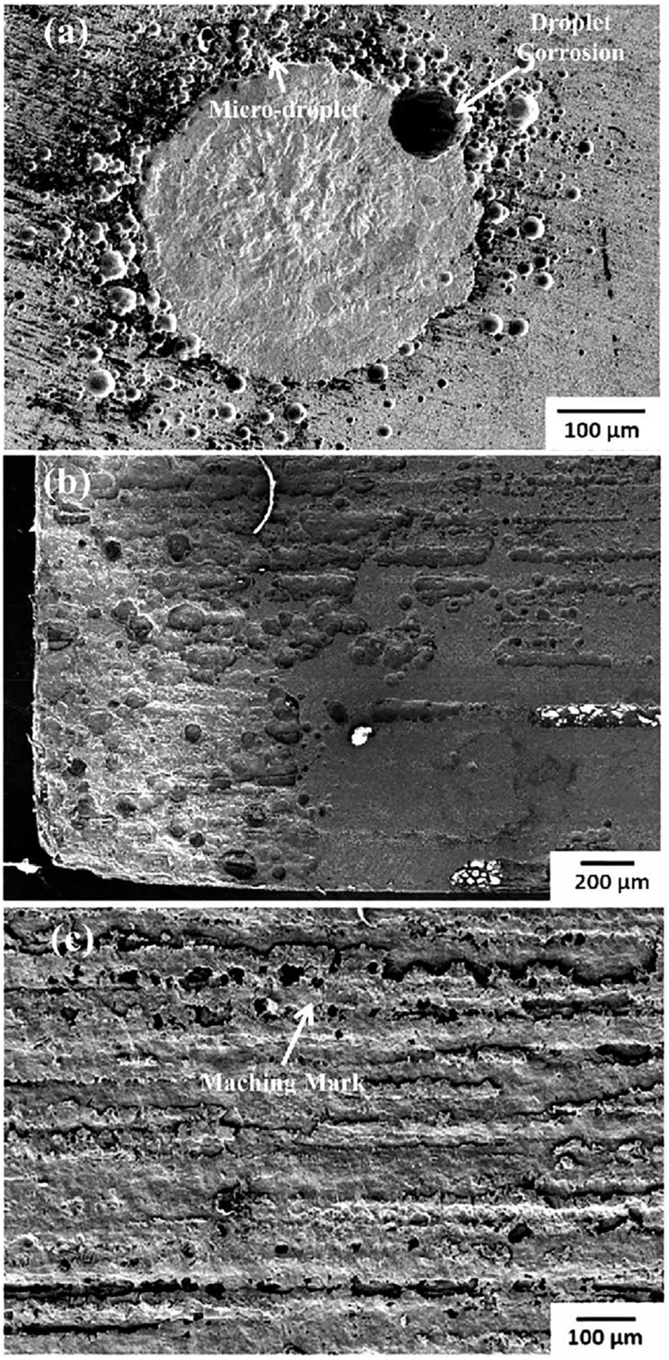
Corrosion morphology of 316L (EP) with a mixture of H2O and HCl: (a) 720 h, (b) 1848 h, (c) 4224 h (Lequien and Moine 2021). Reprinted with permission; copyright 2021 John Wiley and Sons.
Tomari (1997) dried SUS316L (EP) in the air to adsorb sufficient moisture to the specimen surface and exposed it to HCl gas. Granular deposits development, observed by SEM, revealed that higher atmosphere temperatures resulted in more serious corrosion. SUS316L is a stainless steel for semiconductors produced following the standard of semiconductor manufacturing industry (SEMI F20).
The corrosion of stainless steel is linked to the moisture concentration in the gas mixture (Fine et al. 1995; Smudde et al. 1995). As shown in Figure 11, in H2O and HBr mixture, the corrosion rate increases exponentially when the moisture concentration exceeds a critical value (10 ppm). The typical corrosion morphology is the presence of a thin layer of granular deposits in the central part, surrounded by a circular area of 5–10 μm, consistent with the shape of droplet corrosion. EDS analysis determined the deposited crystals in the central part of the feature to be FeBr3-χH2O, and elemental bromine (Br) was detected in the corrosion pit wall below the crystals.
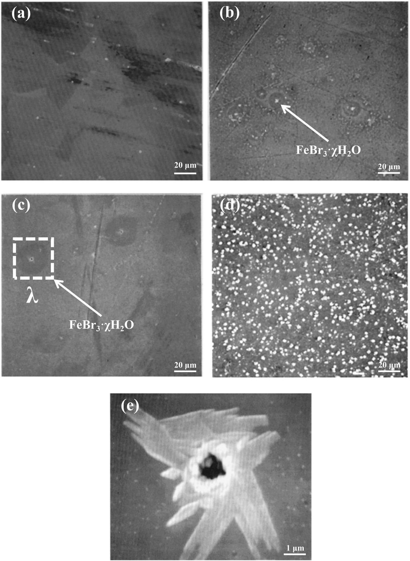
Corrosion morphology of 316L (EP) with hydrogen bromide gas containing different moisture concentrations: (a) 0.2 ppm, (b) 10 ppm, (c) 100 ppm, (d) 1000 ppm, (e) enlarged view of area λ (Fine et al. 1995). Reprinted with permission; copyright 1995 IOP Publishing.
2.1.4 Corrosion mechanism in welded joints of gas pipelines
Welding is inevitably used to connect gas pipelines in gas delivery systems. However, welded joints are vulnerable to corrosion, so clarifying their corrosion mechanisms in the semiconductor manufacturing industry is necessary. The austenitic stainless steel weld zone metal (WM) is a cast iron structure (Cui and Lundin 2005) consisting of an austenitic with 2–10 % δ-ferrite. The welded joints are divided into weld, fusion and heat-affected zones (HAZ), each with different characteristics, as shown in Figure 12 (He and Xing 2019).
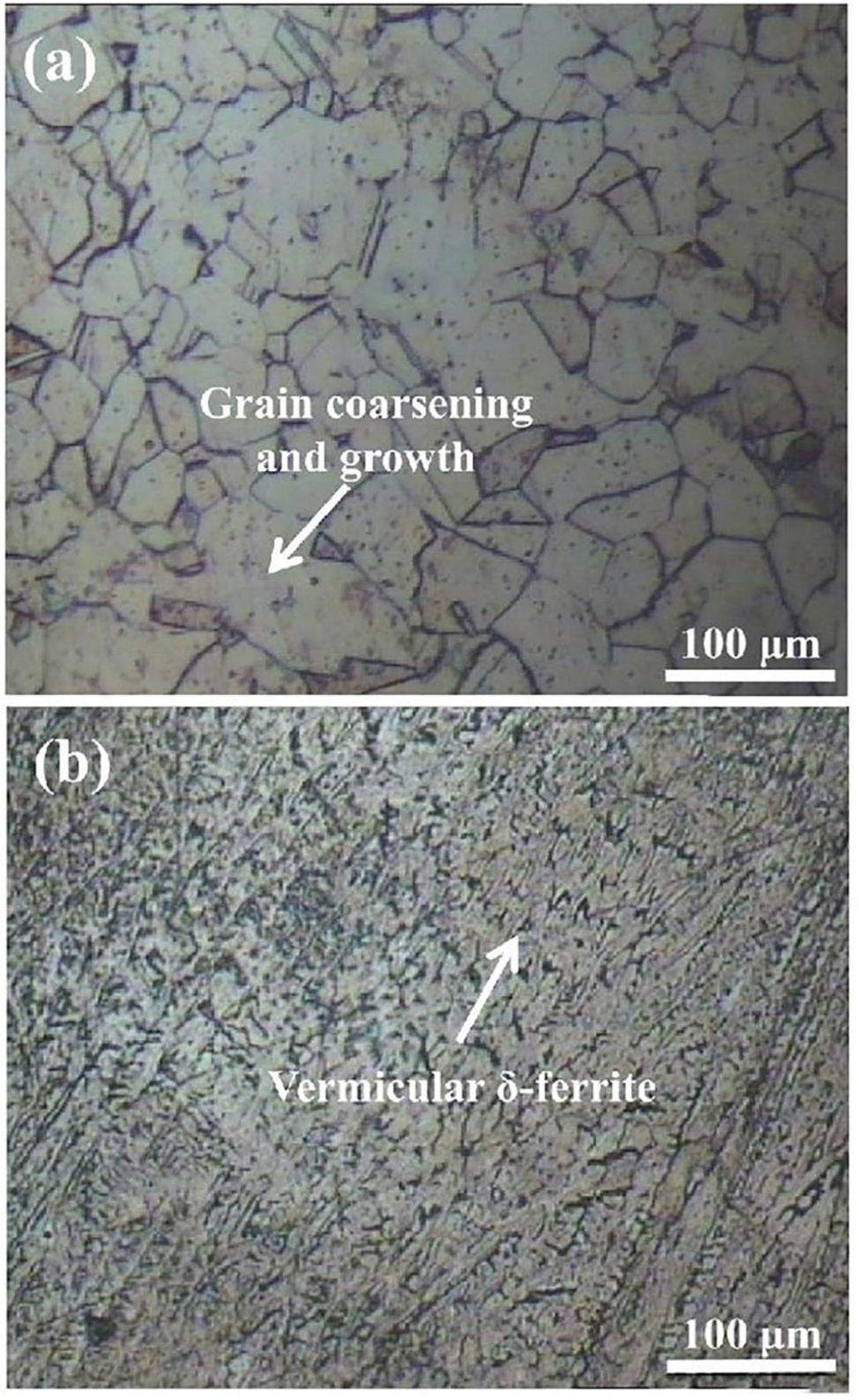
Microstructure of welded joints by TIG: (a) heat affected zone, (b) weld (He and Xing 2019). Reprinted with permission; copyright 2019 IOP Publishing.
Cui and Lundin (2007) deposited 316 on the base metal 304 by shielded metal arc welding (SMAW). Subsequently, a 3 % FeCl3 solution was used for immersion testing. The initial corrosion attack is in austenite instead of ferrite. Cleslak et al. (1982) investigated the chromium (Cr) and nickel (Ni) segregations within dendrites in austenitic weld metal, suggesting that solidification produces Cr and Ni-depleted zones in the crystal core, thus, reducing the corrosion resistance of austenite.
In the welded joint, the HAZ is an obvious weak corrosion site due to the sensitization of austenitic stainless (Lu et al. 2020; Trigwell and Selvaduray 2005). The sensitisation of weldments refers to the rapid carbon diffusion to grain boundaries in the temperature range of 450 and 850 °C, precipitating the Cr-rich carbides (M23C6) near the grain boundaries (Kumar et al. 2015). Cr concentration reduces to well below 12 wt% due to the precipitation of M23C6 near the grain boundaries, known as the Cr-depleted zones. At this point, the corrosion resistance at the grain boundary is reduced and prone to intergranular corrosion (Kumar et al. 2015). The susceptibility to intergranular corrosion depends on the Cr concentration variation and the width of the Cr-depleted zone (Zhang et al. 2013).
In addition, the molten zone shrinks during the cooling and solidification of pipe welding, and the base material adjacent to HAZ produces residual tensile stresses to resist deformation, further increasing the corrosion susceptibility of the heat-affected zone.
Smudde et al. (1995) and Fine et al. (1995) described that the corrosion rate of 316L (EP) welded specimens increased with moisture content in HBr gas through gas mixture exposure experiments, as shown in Figure 13.
Corrosion morphology of 316L (EP) welded specimens: (a) 0.5 ppm, (b) 10 ppm, (c) 100 ppm, (d) 1000 ppm (Fine et al. 1995). Reprinted with permission; copyright 1995 IOP Publishing.
The heat tint appears after welding stainless steel in the joint area, and its colouring depends on the welding conditions (Łabanowski and Głowacka 2011). After welding, a thicker oxide layer is formed on the surface with colour variation due to the light interference effect. During the oxide layers formation, the Cr content in the material decreases, thus, reducing the corrosion resistance of the welded joint (Fuertes et al. 2017). Removing the heat tint in the semiconductor manufacturing industry is necessary. The removal of heat tint can be divided into three stages: (1) Removal of oxide film by mechanical grinding, (2) the removal of Cr-depleted surface via chemical cleaning or electrolytic polishing, and (3) the improvement in corrosion resistance by passivation, found in ASTM A380/A380M and ASTM A967 (Łabanowski and Głowacka 2011).
When the thermal source acts on the weld material surface, it experiences a sharp heat-up. Without considering the vaporization of elements in the melt pool, the stainless steel melt pool soon boils (Zacharia et al. 1991), as shown in Table 3. However, the cooling effect accompanying evaporation limits the temperature of the melt pool; therefore, the welded joint exhibits partial vaporization and uneven distribution of elements.
Melting and boiling points of major elements at welded joints.
| Elements | Melting point (°C) | Boiling point (°C) |
|---|---|---|
| Fe | 1538 | 2750 |
| Mn | 1244 | 1962 |
| Ni | 1455 | 2730 |
| Cr | 1857 | 2672 |
| Mo | 2610 | 5560 |
Block-Bolten and Eagar (1984) suggested that the higher percentage of manganese (Mn) in the stainless steel results in faster vapourization, with Mn being the main element in the melt pool. Figure 14 illustrates that Mn has the highest vapour pressure from a thermodynamic viewpoint, and vaporization occurs preferentially. The composition of melt pool vapour is examined. In the initial melting stage, the Mn element dominates the gas phase composition, and after a sustained period, the Fe element gradually rises.
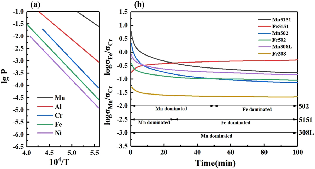
Vaporization of Mn elements in the process of welding. (a) Curves of temperature versus vapour pressure for different elements, (b) curves of melt pool vapour composition versus time (Block-Bolten and Eagar 1984). Reprinted with permission; copyright 1984 Springer.
Trigwell and Selvaduray (2005) found a blue–brown discolouration in the HAZ region associated with the Mn deposition near the weld after evaporation. In 316L stainless steel, the vapour pressure of Mn is higher than other elements, and it tends to evaporate during the welding process and is subsequently deposited in the HAZ adjacent to the weld, accelerating the corrosion.
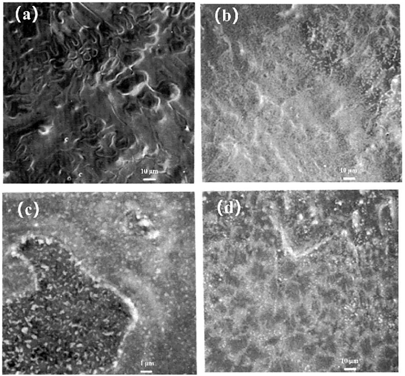
Hattori et al. (1994) reported Mn deposits downstream of the weld centre, resulting from post-vapour deposition of Mn during welding. Subsequently, experiments were performed on stainless steel welded joints with different Mn contents. They also proposed a mechanism to deposit Mn after vapourization to accelerate corrosion. Figure 15 shows a surge of Mn content downstream of a high Mn stainless steel weld, where the peak was at 5 mm. Mn coexists with iron (Fe), Cr and Ni oxides in the form of MnO2. MnO2 results from oxidizing extremely fine Mn particles by residual moisture or oxygen on the surface. The corrosion rate is further accelerated by H2O, produced by the MnO2 reaction with HBr.
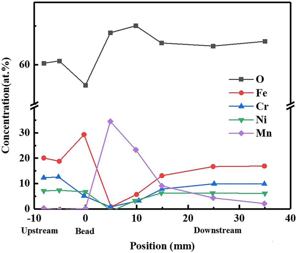
Elemental composition of the upper and downstream surfaces of high manganese stainless steel after welding (Hattori et al. 1994). Reprinted with permission; copyright 1994 Japan Society of Applied Physics.
2.2 Corrosion mechanisms of structural components inside chambers at high temperatures
In the early 1990s, stainless steel was used as a chamber material in the semiconductor manufacturing industry. With the development of aluminium alloy technology, surface-treated aluminium alloys are now gradually used as a component material in reaction chambers. However, several structural components in chambers are still made of stainless steel. Since the stainless steel structural components are inside the chamber, their environment differs significantly from the stainless steel in the gas delivery system. The corrosion resistance of stainless steel in this service environment and the corrosion mechanisms need to be investigated. In vapour phase epitaxy equipment, the gas temperature in the chamber’s centre reaches 500 °C. The stainless steel parts are at a certain distance from the reaction centre in the cavity, and the stainless steel is at a lower temperature range than the gas temperature due to the heat propagation path of thermal radiation in the vacuum.
Since the temperature is above the boiling point of water, the water molecules are stored as a vapour phase during service. The mechanism of moisture-accelerated corrosion of stainless steel in the ambient/low-temperature environment is not valid in the service environment. When stainless steel materials are placed in the above service environment for a long time, the material undergoes thermal ageing, dominated by spinodal decomposition and carbide precipitation. Therefore, the impact of thermal ageing on the stainless steel materials’ performance needs to be explored as a priority.
2.2.1 Thermal ageing behaviour of stainless steel
Nowadays, the austenitic stainless steel manufacturing technology is excellent. However, owing to the limitations of non-equilibrium rapid solidification of the manufacturing process (Hong et al. 2002), a slight amount of ferrite is inevitable in austenitic stainless steels (Elmer et al. 1989; Li et al. 2021a,b; Warren et al. 2015). Ignoring these ferrites in the semiconductor manufacturing industry with ultra-high purity requirements is not recommended, even if the ferrite content is extremely low. Moreover, austenitic stainless steel welds have duplex microstructures consisting of an austenite substrate with approximately 5–12 % ferrite (Chandra et al. 2012). Ferrite in welds can effectively avoid thermal cracking (Chandra et al. 2012; Gill et al. 1989; Lee et al. 2018). However, when stainless steel is under long-term service at 280–330 °C, ferrite undergoes structural transformation, increasing the strength and hardness, decreasing the plasticity and toughness, and thermal ageing embrittlement (Lin et al. 2019; Sahu et al. 2009). Microstructural changes due to thermal ageing can facilitate corrosion (Was et al. 2011).
Microstructural changes in thermal ageing at 280–330 °C are characterized by unstable ferrite decomposition (spinodal decomposition) and the G phase precipitation (Lee et al. 2018). The unstable decomposition of ferrite is characterised by Fe-rich (usually noted as α) and Cr-rich (usually noted as α′) zones. BCC structure’s iron-rich and Cr-rich phases have similar lattice constants (Chandra et al. 2012). The difference in Cr content between α and α′ phases increases with thermal ageing. The α-phase contains a small amount of Cr and is susceptible to corrosion. Figure 16 illustrates the unstable decomposition morphology of ferrite with an orange peel appearance (Jeong et al. 2022). The G phase is a intermetallic nickel silicide that correlates well with Ni. The G phase precipitates in the ferrite phase during thermal ageing, with a lattice constant four times that of ferrite, as FCC intermetallic silicides. Figure 17 shows the G phase precipitation morphology and composition (David et al. 1996; Kong et al. 2023). The G-phase is preferentially nucleated at α and α′ phase boundaries and acts synergistically with ferrite spinodal decomposition. Ni are repelled by α and α′ regions, diffusing and aggregating in the middle of α and α′ phases, forming clusters, precipitating into G-phase (Jeong et al. 2022; Kong et al. 2023).
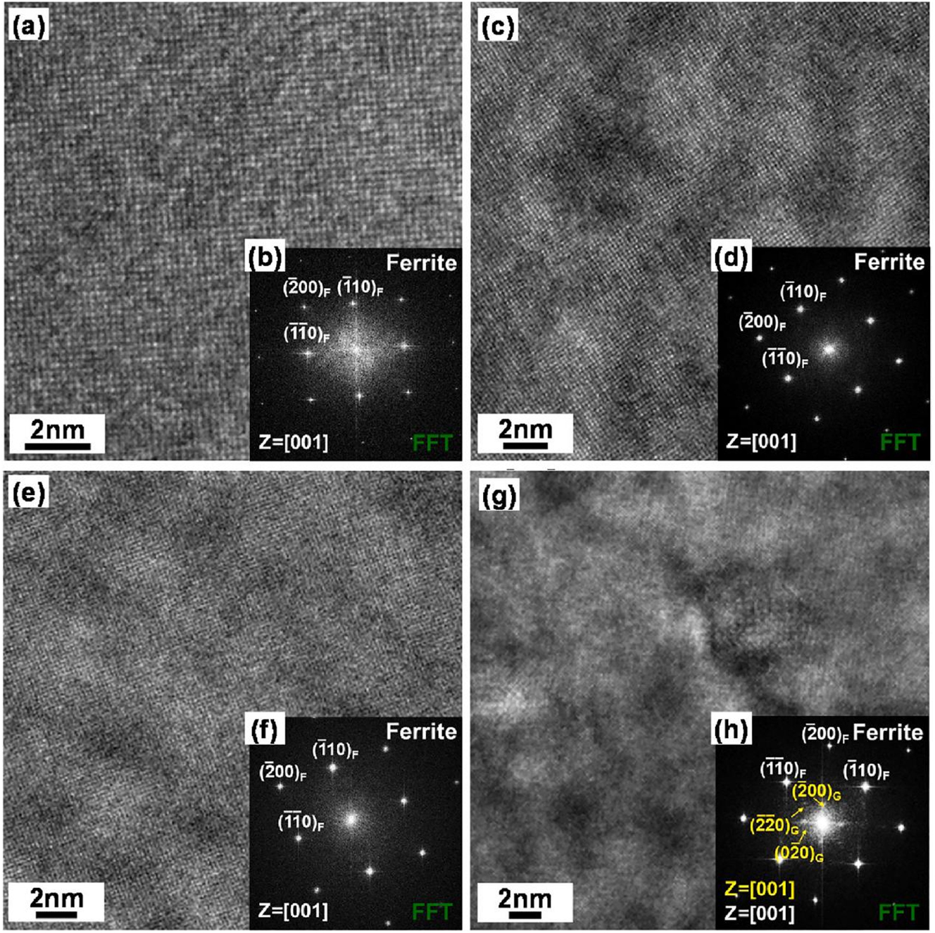
TEM analysis results of ferrite in the 316L: (a and b) untreated, (c and d) ageing at 400 °C for 5000 h, (e and f) ageing at 400 °C for 10,000 h, (g and h) ageing at 400 °C for 20,000 h (Jeong et al. 2022). Reprinted with permission; copyright 2022 Elsevier.
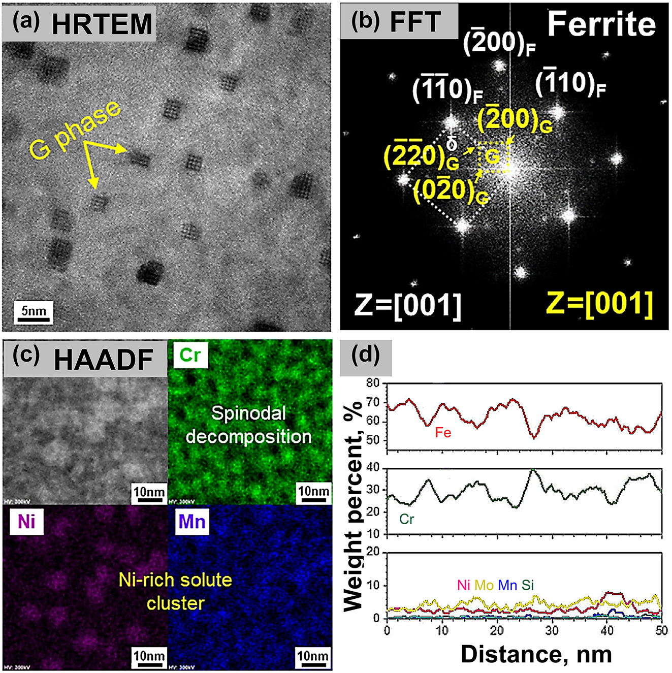
TEM analysis results for ferrite at 400 °C for 20,000 h: (a) HRTEM image, (b) resultant FFT taken in (a), (c) STEM/EDS mapping, (d) compositional line scan profile (Kong et al. 2023) (no permission is required).
Since the sluggish thermal ageing rate, behaviour under service conditions is studied by accelerated methods. The materials’ structural transformation (thermal ageing mechanism) occurring under service and accelerated thermal ageing temperatures are consistent (Lin et al. 2019; Pumphrey and Akhurst 1990). Chung and Chopra (1986) demonstrated the effectiveness of accelerated thermal ageing, which is generally considered a thermally activated process in stainless steel and obeys the Arrhenius Formula. Temperature and time for accelerated thermal ageing are determined in the laboratory to simulate the thermal ageing behaviour at service temperature. Although the activation energy is a function of temperature, the thermal ageing activation energy is approximated as a constant over a suitable temperature (Lin et al. 2019).
The structure variation due to spinodal decomposition possesses the highest embrittlement rate at 475 °C, known as the 475 °C embrittlement phenomenon (Sahu et al. 2009). The thermal ageing characteristics of structure variation are transformed when the temperature is higher than 475 °C.
Thermal ageing structure transformation of stainless steel at 500–850 °C is characterized by carbide precipitation (Trillo 1997). Carbon remains in austenite in a supersaturated state, and when heated to an appropriate temperature for a sufficient period, this supersaturated carbon element precipitates as a carbide. As shown in Figure 18, there is a decrease in Cr content at grain boundaries. Ding et al. (2009) described that precipitate phases at grain boundaries are chromium-rich carbides (M23C6) by thermodynamic calculations and TEM.
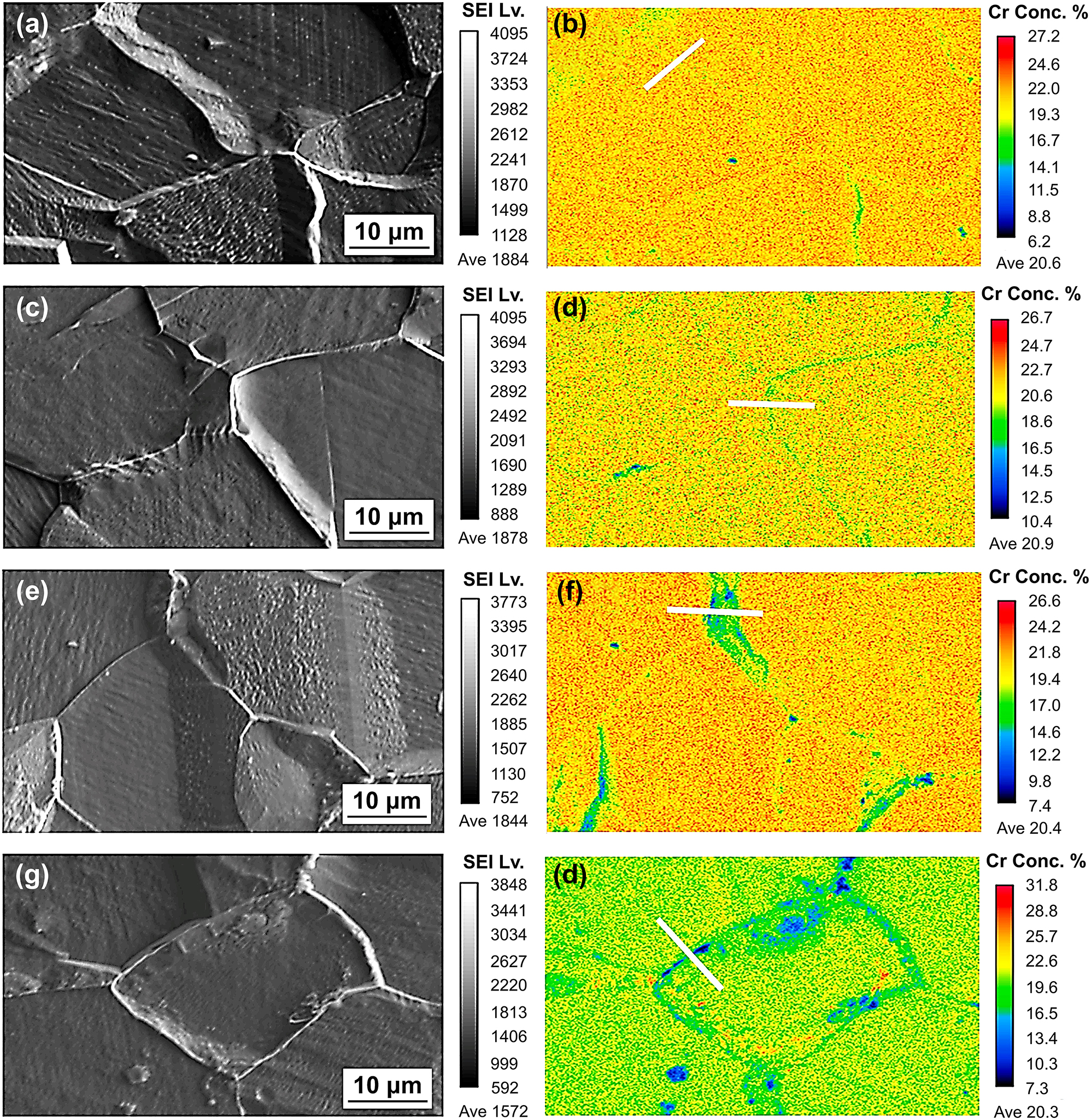
Element distribution of stainless at 650 °C under different ageing time: (a, b) 0 h, (c, d) 1 h, (e, f) 5 h, (g, h) 48 h (Wang et al. 2021). Reprinted with permission; copyright 2021 Elsevier.
The temperature range for M23C6 precipitation during thermal ageing is 500 °C to 850 °C (Trillo 1997). In addition, the precipitation kinetics of M23C6 is associated with the stainless steel chemical composition and processing histories (Allahyari et al. 2005; Ding et al. 2009; Li 2014; Li et al. 2021a,b). Figure 19 shows that the corrosion resistance of stainless steel is significantly reduced after thermal ageing, and the longer time result in worse corrosion resistance (Wang et al. 2021).
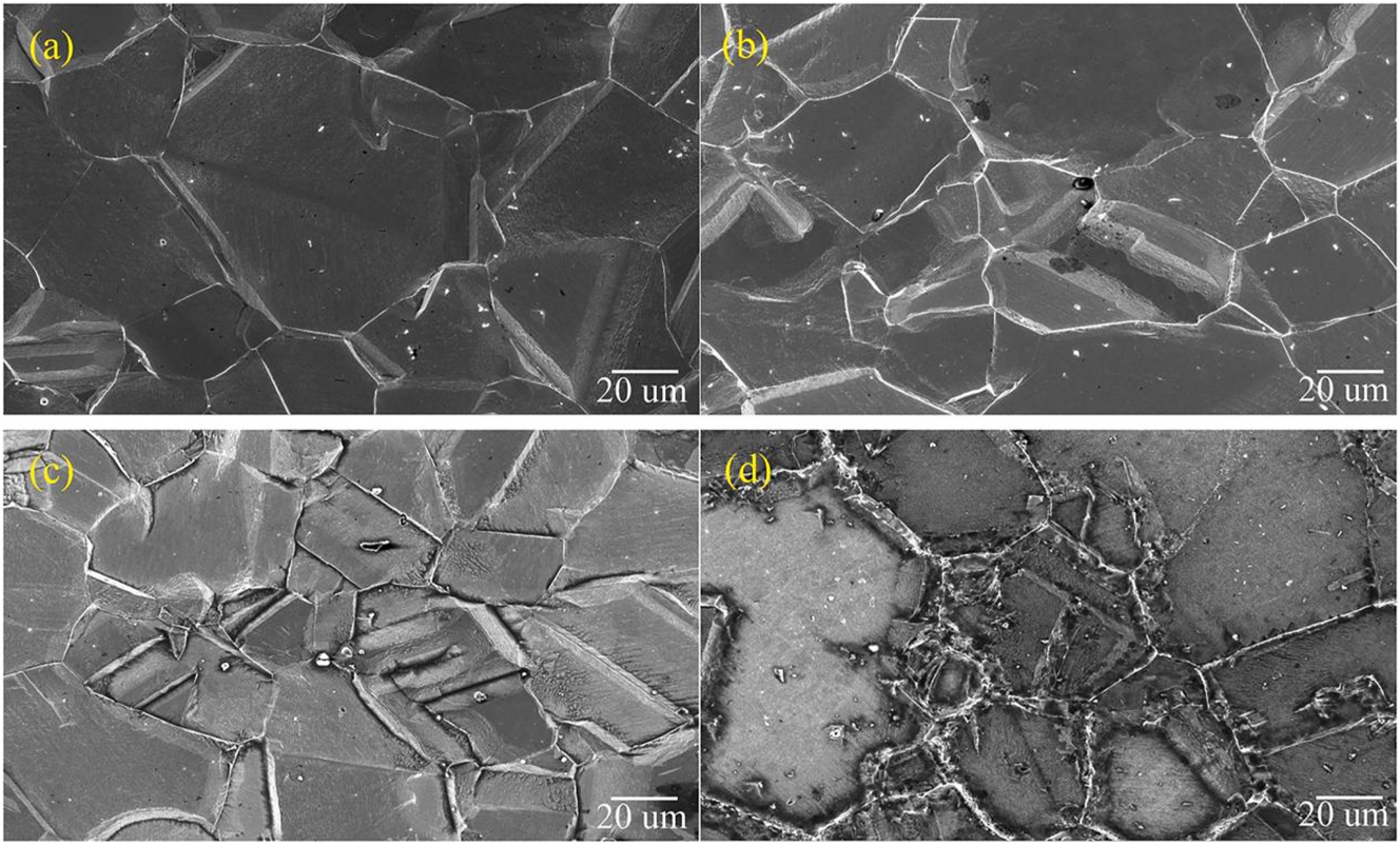
Corrosion morphology of specimens immersed in 1 M hydrochloric acid for 7 days after the different thermal ageing time at 650 °C: (a) 0 h, (b) 1 h, (c) 5 h, (d) 48 h (Wang et al. 2021). Reprinted with permission; copyright 2021 Elsevier.
The precipitation time for carbides varies at different temperatures. The carbide precipitation times of stainless steels at 500 °C to 850 °C are summarized in the literature (Allahyari et al. 2005; Ding et al. 2009; Li 2014; Li et al. 2021a,b). The higher the temperature, the more rapid the diffusion and the shorter the time for carbide formation, as shown in Figure 20.
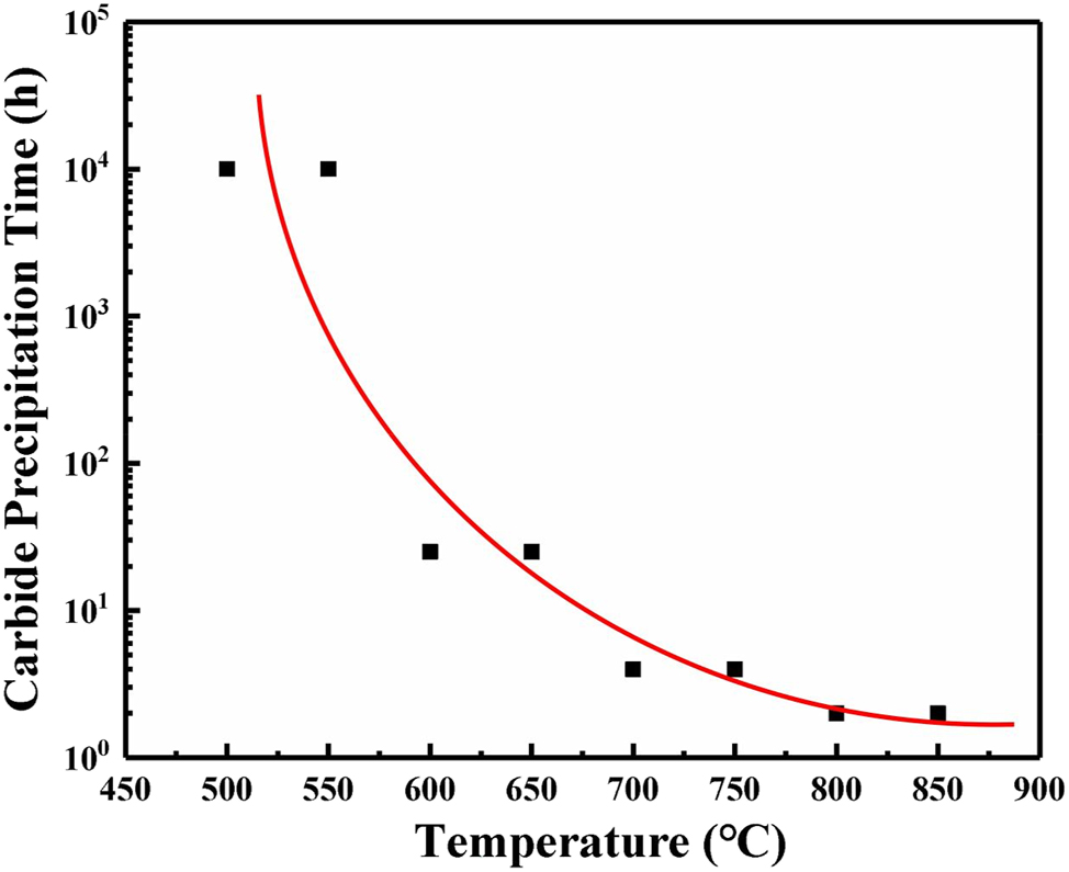
Statistics and fitting of carbide precipitation times for stainless steels at different temperatures (Allahyari et al. 2005; Ding et al. 2009; Li 2014; Li et al. 2021a,b).
2.2.2 Vaporisation behaviour of corrosion products at high temperatures
The reaction mechanism between corrosive gases and metals in a high-temperature vacuum environment significantly differs from that in a conventional atmospheric environment. Under conventional corrosive environments, corrosive species dissolve in water to produce ionic conductors, resulting in electrochemical corrosion. However, under a high-temperature vacuum environment, water exists in trace amounts of gas phase molecules, depicting a weak accelerating effect on corrosion, and the overall reaction is predominantly chemical. Taking the corrosion of stainless steel in HCl gas as an example, the reactions are as follows:
Metal halides are extremely volatile, and their vapourization at high temperatures and low pressures must be considered (Speight 2005).
Ihara et al. (1981, 1982a, 1983 investigated the corrosion behaviour of metals in pure HCl gas at high temperatures and 1 atm in a confined stationary space. Figure 21 indicates that the corrosion behaviour of Fe/Cr/Ni in HCl gas at high temperatures is determined by the formation and sublimation of ferrous chloride. Below a certain temperature, corrosion products are constantly attached to metal surfaces and do not undergo vaporisation. When the temperature exceeds a certain level, corrosion products undergo vaporization. The gaseous reaction products leave the surface, and almost no corrosion product adheres to the specimen surface. The middle-temperature range is a transition zone; some corrosion products undergo vaporization, while others adhere to the surface. The reaction of Cr with HCl at 800 °C undergoes complex weight changes. It is speculated that gaseous CrCl3 is supersaturated in the chamber during the final reaction stage, resulting in redeposition on the specimen surface.
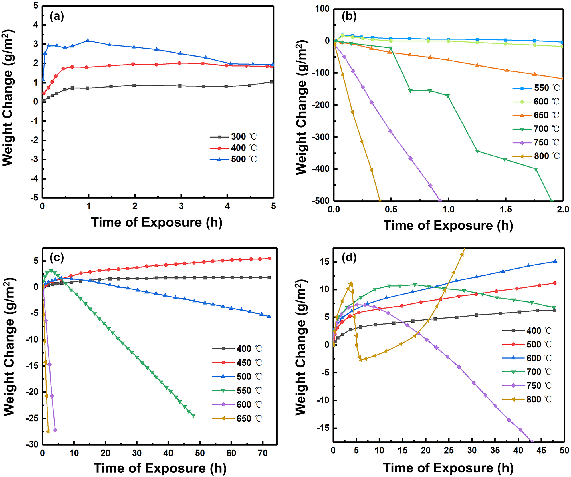
Curves for thermogravimetric experiments in a confined stationary space: (a, b) pure Fe, (c) pure Ni, (d) pure Cr (Ihara et al. 1981, 1982a, 1983). Reprinted with permission; copyright 1981, 1982a, 1983 Elsevier.
However, the interaction between Fe, Ni and Cr must be considered for alloys such as stainless steel. When the percentage of Ni content in the alloy increases, it could significantly inhibit the product vaporisation of the alloy (Ihara et al. 1982b), as shown in Figure 22. Therefore, elements in stainless steel influence the corrosion product vaporisation.
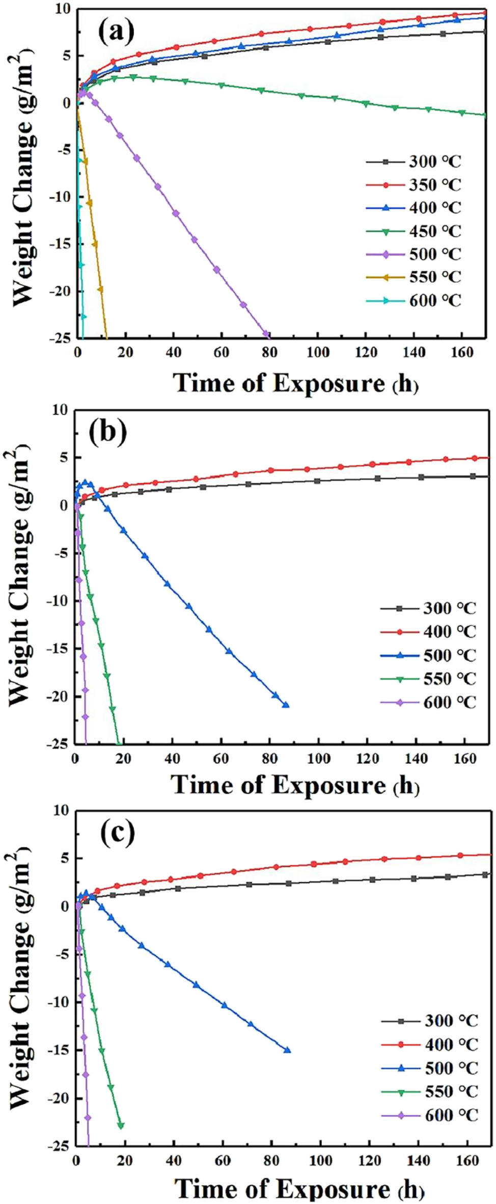
Curves for thermogravimetric experiments in a confined stationary space: (a) pure Fe, (b) Fe–12Ni, (c) Fe–20Ni (Ihara et al. 1982b). Reprinted with permission; copyright 1982b The Japan Institute of Metals and Materials.
The influence of the vaporization behaviour of HCl gas is more prominent in the gas mixture. Chlorosilane gas streams are frequently used at high temperatures (>500 °C) in semiconductor, polysilicon and fumed silica sectors. The chlorosilane gas streams mainly consist of hydrogen, tetrachlorosilane and HCl. The main reaction equations are as follows;
Aller et al. (2015, 2016 reported that the corrosion of 316L stainless steel completely differs in chlorosilane gas streams at different temperatures. When the temperature exceeds ferrous chloride’s solid gas transition temperature, the vaporization phenomenon occurs, prompting the corrosion products to be rarefied and easily dislodged. With the increase in HCl concentration in the chlorosilane gas stream, the protective properties of corrosion products sharply decrease (Figure 23).
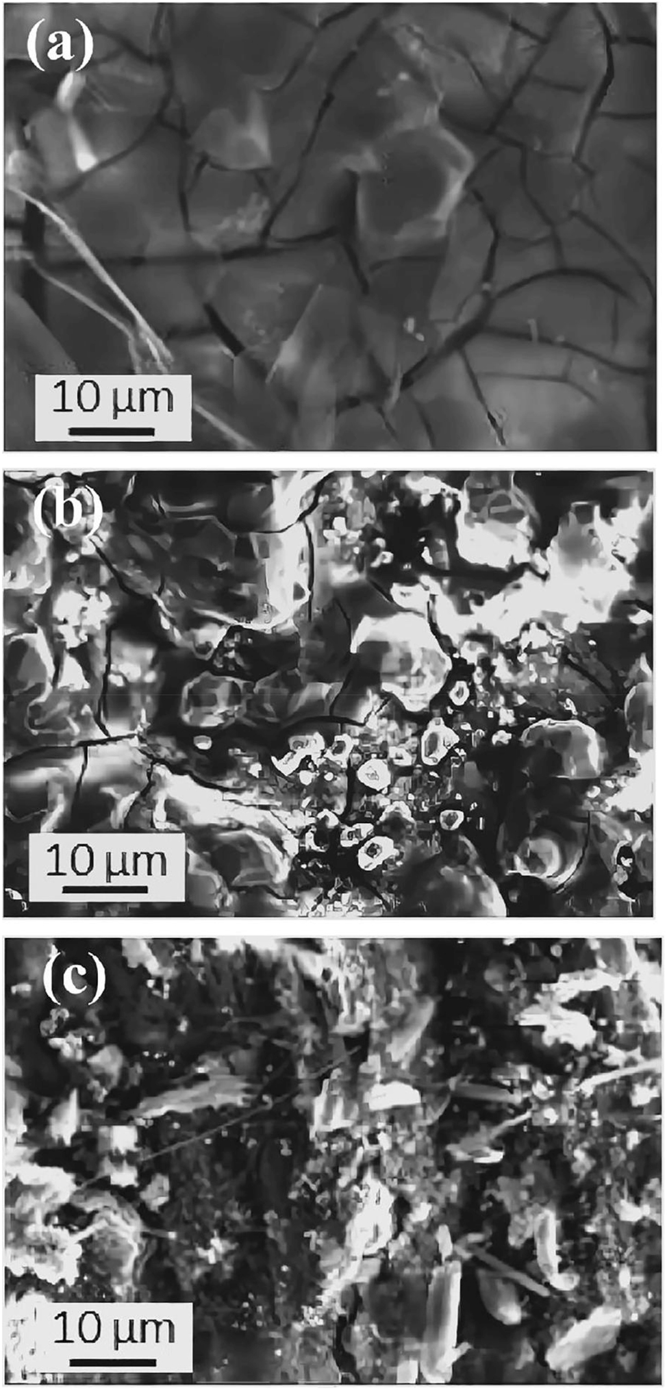
Corrosion morphology of a gas mixture (SiH4 and HCl) with Fe–Cr alloy at 550 °C for 100 h: (a) 0.014 mol/L HCl, (b) 0.025 mol/L HCl, (c) 0.057 mol/L HCl (Aller et al. 2016). Reprinted with permission; copyright 2016 IOP Publishing.
When the HCl content in the chlorosilane gas stream is minimal and no vaporisation occurrs, the corrosion products are composed of dense FeSi after etching by the chlorosilane gas stream (Figure 24), protecting the material and slowing down the corrosion. HCl in the chlorosilane gas stream is a key factor affecting the corrosion resistance of stainless steel.
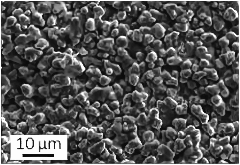
Corrosion morphology of a gas mixture (without HCl) with Fe–Cr alloy at 550 °C for 100 h (Aller et al. 2016). Reprinted with permission; copyright 2016 IOP Publishing.
3 Anti-corrosion technology for stainless steel in the semiconductor industry
To face the semiconductor manufacturing industry’s stainless steel corrosion challenge, many anti-corrosion technologies have been developed based on identified corrosion mechanisms. Anti-corrosion technologies can be summarised in three aspects. First, the purification of the material using metallurgical innovations, particularly VIM and VAR technologies. The ultra-high purity stainless steel minimizes these inclusions, thus, inhibiting the breakdown of passivation film (Krawiec et al. 2006; Szummer et al. 1993; Wang et al. 2023). Second, smoothing the surface via polishing technology reduces the damage due to abrasive chips, stress and improves corrosion resistance. The polished surface exhibits “hydrophobic” behaviour, reducing moisture adsorption and indirectly improving the condensation threshold for moisture (Tsuji et al. 2017; Siefering and Whitlock 1994). Third, surface treatment and coating technology can improve the stainless steels corrosion resistance, such as passivation (He et al. 2009; Liu et al. 2015) and electroplating/electroless nickel-based coatings (Kim et al. 2022; Shozib et al. 2022).
3.1 Material purification
Stainless steel produced by conventional melting techniques exhibits excellent corrosion resistance; however, it does not satisfy the corrosion resistance requirements of the semiconductor manufacturing industry. After smelting, non-metallic inclusions, such as MnS and Al2O3, are inevitably retained inside the material. MnS inclusions are favourable nucleation sites of pitting for chlorides and other deleterious species in the aqueous solution (Eklund 1974; Krawiec et al. 2006). Similarly, Al2O3 is among the most important inclusions in reducing the corrosion resistance of stainless steel (Lim et al. 2001; Park et al. 2003). The pits initiate at micro-crevices around Al2O3 inclusions (Wang et al. 2023). In addition, the rapid change in temperature prompts Cr and carbon (C) to precipitate at the grain boundary position in the form of Cr23C6 during the pipeline welding process. Carbide precipitation depleted chromium at grain boundaries. Thus, the intergranular corrosion resistance is reduced. Therefore, the material’s purity can be improved by reducing these inclusions and the carbon content, thus effectively improving the stainless steel’s corrosion resistance.
Enhancing the purity of stainless steel in the semiconductor manufacturing industry with excellent metallurgical techniques to strictly control the C, sulphur (S), Mn and aluminium (Al) content is possible. Common processing processes include argon oxygen decarburization (AOD), AOD/VAR, vacuum oxygen decarburization (VOD)/VAR or VIM/VAR. Stainless steel produced by primary melting technology normally transports relatively non-corrosive gases. Stainless steels for transporting corrosive gases must be produced using secondary or vacuum melting technology (Collins 1997).
AOD can reduce material consumption and economic costs while increasing stainless steel productivity (Collins 1997). Figure 25(a) shows that the charge from the electric arc furnace is moved to the AOD vessel, forming a slag layer at the top of the furnace charge. Argon, oxygen and nitrogen are injected from the bottom at sonic velocity, and the gas blown from the bottom can reduce the carbon content without excessive Cr oxidation (Hu et al. 2020; Wei and Zhu 2002).
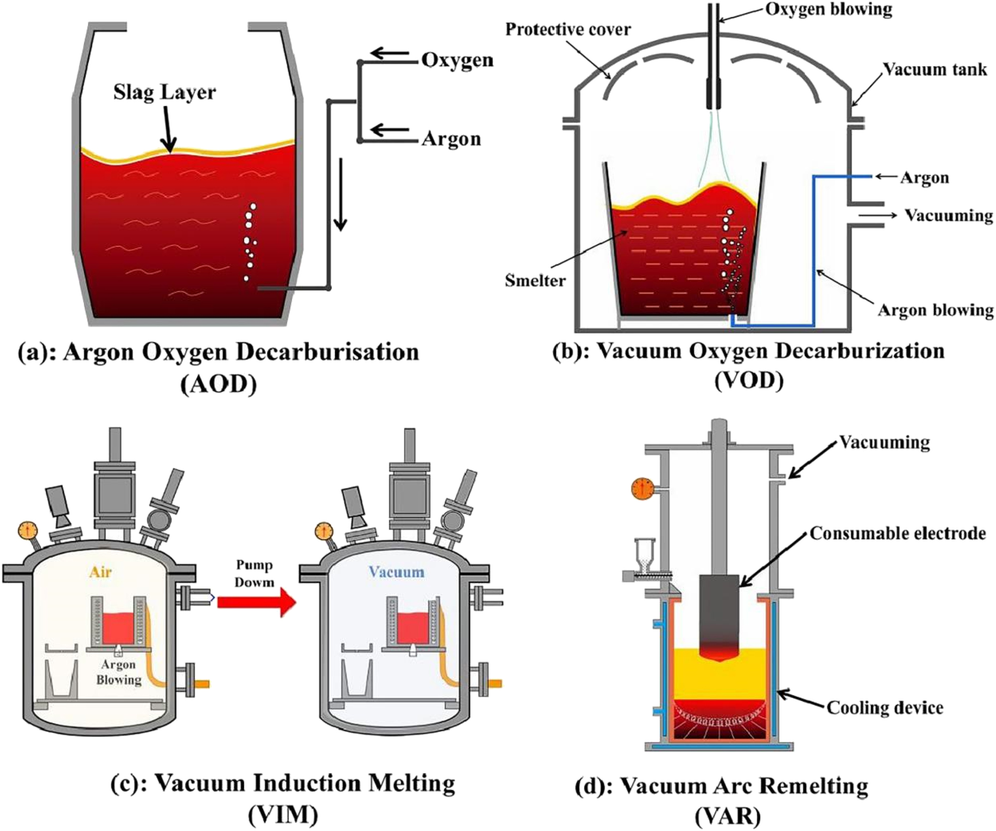
Smelting and refining methods of stainless steel. (a) Schematic diagram of argon oxygen decarburisation (AOD), (b) schematic diagram of vacuum oxygen decarburization (VOD), (c) schematic diagram of vacuum induction melting (VIM), (d) schematic diagram of vacuum arc remelting (VAR).
VOD is similar to AOD except that the melting process occurs under a 10–100 mbar vacuum, and only a small amount of Ar is injected from the bottom, mainly for agitation. The cleanliness of VOD material is similar to that of the AOD (Ding et al. 2000; Xu et al. 2009).
VIM is a primary melting process where furnace charge is melted in an inductively heated crucible under a vacuum of 10-3-1 mbar. VIM has a wide application range in producing high-temperature alloys. The melting equipment is shown in Figure 25(c). Under atmospheric conditions, violent oxidation reactions occur during high-temperature alloys’ melting. Under vacuum, almost no oxidation reactions occur, reducing the oxide inclusions. The extent of VIM metallurgical refinement is inferior to that of AOD in decarbonisation, deoxidation, phosphorus removal, and desulphurisation. VIM is more expensive than AOD due to the furnace charge’s purity requirements and the equipment’s vacuum maintenance (Frenzel et al. 2004; Otubo et al. 2006; Tan et al. 2014).
VAR is a secondary melting process of melting ingots (AOD or VIM melting) utilizing a direct current arc under a high vacuum of 104-10-2 mbar. High-quality ingots with homogeneous organization and no component segregation are produced by VAR technology, and the melting equipment is shown in Figure 25(d). Nitrogen and hydrogen are dissolved during the vacuum arc remelting process, while impurity elements with high vapour pressure (arsenic, lead, tellurium, selenium, bismuth, silver, copper) and oxygen/oxide content are also reduced. During VAR, a portion of the ingot is solidified, another portion is molten, and the other portion is getting ready to melt. The solidification rate can be kept stable to control the ingot structure (Davidson et al. 2000; Wang et al. 2008; Zanner and Bertram 1985).
316LVV with double vacuum melting (VIM + VAR) exhibits a minimal C content compared to conventional 316L, preventing intergranular corrosion caused by gas pipeline welding, as shown in Table 4. Extremely low Mn content prevents elements evaporation from the melt pool and reduces inclusions content. The extremely low S and Al content and the increased molybdenum (Mo) content can improve corrosion resistance. Therefore, metallurgical melting can purify stainless steel and improve its corrosion resistance.
Table of elemental composition of 316L after melting.
| Material | Chemical composition (mass %) | |||||||
|---|---|---|---|---|---|---|---|---|
| C | Si | Mn | S | Ni | Cr | Mo | Al | |
| 316L (VIM-VAR) | 0.006 | 0.13 | Ultra low | Ultra low | 14.7 | 16.7 | 2.25 | Ultra low |
| 316L (AOD-VAR) | 0.007 | 0.23 | 0.23 | Ultra low | 14.7 | 16.9 | 2.23 | Low |
| 316L (AOD) | 0.012 | 0.38 | 0.45 | Low | 12.2 | 16.9 | 2.03 | Low |
| SEMI F20 HP/UHP grade | ≤0.030 | ≤1.00 | ≤1.50 | ≤0.010 | 10.0–14.0 | 16.0–18.0 | 2.0–3.0 | ≤0.01 |
| General 316L | 0.013 | 0.28 | 1.84 | 0.014 | 12.1 | 16.8 | 2.02 | 0.01 |
3.2 Polishing techniques for smoothing surface
In semiconductor manufacturing industries, the vacuum and purity requirements are extremely high. In addition, the corrosion mechanism shows that corrosion is relevant from moisture in stainless steel. Therefore, preparing smooth surfaces to reduce background vacuum, grinding and impurity hiding, and moisture adsorption are important directions in anti-corrosion technology.
3.2.1 Mechanical polishing (MP)
Mechanical polishing is a surface treatment with micro-abrasives and soft tools that reduces surface roughness and enhances gloss. Three processes are involved in micro-abrasive particles and the products’ surfaces; sliding, ploughing, and cutting. After mechanical polishing, a work-hardened layer is formed on the material’s surface, the grain size is reduced, and a Beilby layer appears, as shown in Figure 26 (Kaneko and Sato 1990). The Beilby layer is a amorphous surface layer formed during mechanical polishing, with thickness ranging from a few nanometres to a micron. The surface roughness in semiconductor manufacturing is more demanding, and a fine surface finish is required. A lower surface roughness value indicates a smaller difference in height between the raised and depressed surfaces; thus, impurities, debris and pollution cannot hide on the material surface, reducing the specific surface area and slowing down the corrosion rate (Yu 2017). To meet these requirements, electrolytic polishing is used to modify the stainless steel surface in the semiconductor manufacturing industry.
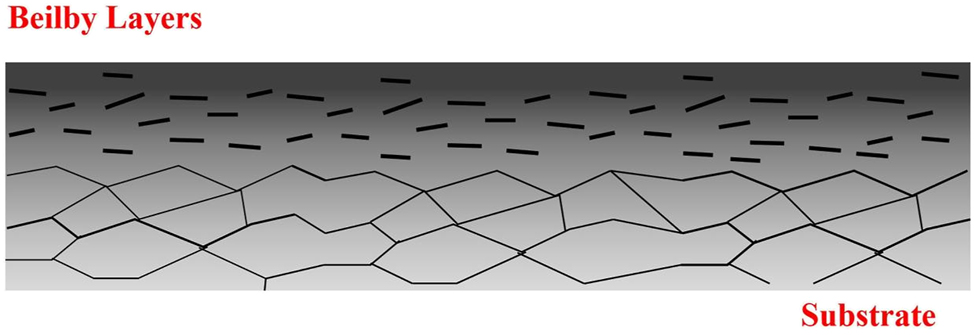
Schematic diagram of the Beilby layer after mechanical polishing.
3.2.2 Electrolytic polishing (EP)
Electrolytic polishing (EP) forms a smooth surface by selective dissolution of microscopic projections on the anode in an electrolytic cell (Hernando et al. 2012; Lee 2000). Figure 27 illustrates that the metal for polishing at the anode undergoes a dissolution reaction, and the inert electrode undergoes a hydrogen evolution reaction.
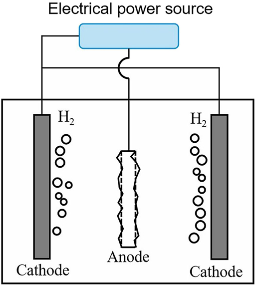
Equipment of electrolytic polishing.
Decreased surface roughness and increased surface gloss during electrolytic polishing are attributed to the selective dissolution of concave and convex areas on the material surface. Therefore, the electrolytic polishing process can be further divided into the anodic smoothing process to reduce surface roughness and the anodic brightening process to increase surface gloss (Li et al. 2005, 2008; Łyczkowska-Widłak et al. 2020; Zhao et al. 2002). The schematic diagram of the two processes is shown in Figure 28.
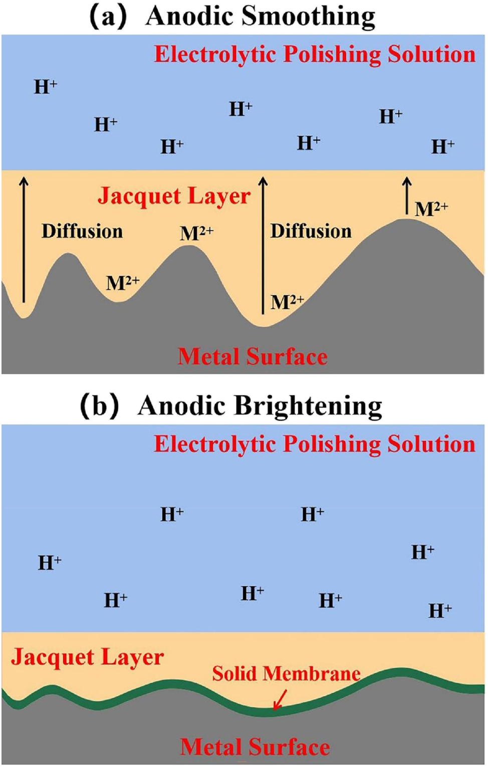
Mechanisms of electrolytic polishing: (a) anodic smoothing, (b) anonic brightening.
The anode smoothing process is a macro-level modification. At the anode, dissolved metal ions constantly enter the adjacent solution and the generation rate of metal ions is higher than that of migration by diffusion into the solution. Various metal ions gradually accumulate on the anode surface. Eventually, a viscous liquid film structure is formed between the electrolyte and metal surface, and the reaction is controlled by diffusion. The viscous liquid film (diffusion layer) is the Jacquet layer. The higher viscosity of the polishing solution facilitates the formation of Jacquet layers. The diffusion rate of metal ions into the electrolyte in the Jacquet layer depends on the concentration gradient between the liquid film and electrolyte, i.e., the current remains constant with increasing voltage. The overall reaction rate depends on diffusion current density. The Jacquet layer is thicker in metal surface depressions and thinner in bumps. The thinner the Jacquet layer, the greater the concentration gradient, resulting in a higher current density. Generally, Jacquet layers are approximately 20 to 80 μm thick. When the surface roughness is within the above range, the selective dissolution of the metal surface occurs (Hickling and Higgins 1952; Landolt 1987; Magaino et al. 1993; Mohan et al. 2001; Uhlig 1940; Yang et al. 2017).
The anodic brightening process is a micro-level modification inducing a mirror glossiness on the metal surface and further reducing the surface roughness. Glossiness is the metal surface’s ability to reflect light. On an ideally smooth surface, the light reflection angle is equal to the light incidence angle, whereas multi-directional scattering occurs on a non-glossy metal surface. More light is reflected when the light is less scattered, and then the surface gloss is high. A surface can exhibit mirror-quality glossiness if the unevenness of the polished surface is less than the wavelength of visible light. In the Jacquet layer, electrolytic polishing generally results in smoothing, not brightening. After the anodic smoothing, the surface roughness of the metal is approximately 0.01–0.1 µm, attributed to incomplete structures near the grain boundaries. During the micro-modification phase, continuously maintained at a high potential, the anode surface generates a thin film. The created film layer is located between the Jacquet layer and the metal surface, distributed at approximately the same thickness. The film allows the crystalline incomplete grains to be preferentially dissolved, removing the microscopic unevenness of the polished surface, further reducing the surface roughness and achieving an anodic brightening on the metal surface (Alkire and Cangellari 1983; Beck 1982; Grimm and Landolt 1994; Grimm et al. 1992; Russell and Newman 1986; West et al. 1992; Williams and Barrett 1956).
Electrolytic polishing is recommended to be only suitable for refining low-roughness surfaces (Lee 2000). To reduce surface roughness, the surface must be mechanically polished before the electrolytic polishing process. Electrolytic polishing usually reduces the roughness by 50–80 %; therefore, the effect of mechanical polishing on surface roughness cannot be ignored. The lower the initial surface roughness after mechanical polishing, the smoother the final polished surface under the same electrolytic polishing parameters, as shown in Figure 29.
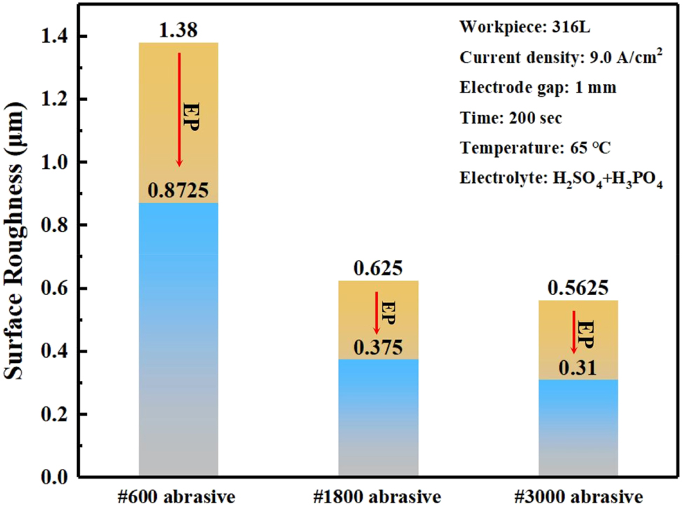
Effect of initial surface roughness on electrolytic polishing.
Electrolytic polishing is sensitive to non-metallic inclusions in stainless steel (Lowery and Roll 1998; Sutow 1980). Electrolytic polishing usually attacks these non-metallic inclusions, with sulphide inclusions being the primary attack location. Sulphide inclusions act as anodes in the electrolytic polishing and are selectively removed. Several pits remain on the surface in the presence of a high amount of sulphide (Figure 30). Therefore, efficient melting technology can reduce the volume percentage of elemental sulphur, generally limiting it to 0.003 % and below (Collins 1997).
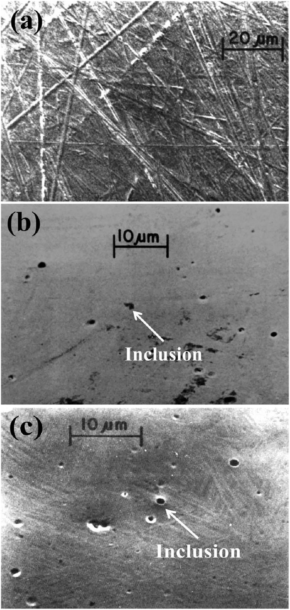
Surface morphology after electrolytic polishing: (a) 0 min, (b) 15 min, (c) 25 min (Sutow 1980). Reprinted with permission; copyright 1980 John Wiley and Sons.
Gibb’s free energy calculations result in a preferred reaction order: MnS < Fe < Al2O3. Oxide inclusions in the electrolytic polishing act as cathodes without dissolution. However, due to the Fe dissolution, the oxide inclusions also fall off the metal surface. After refining and cold working of stainless steel, plastic deformation layers are formed with particle contamination and residual gas adsorption on the metal surface. Degreasing and cleaning are commonly used in semiconductor manufacturing to remove contamination, and baking removes adsorbed gases from surfaces. Moreover, residual stresses and amorphous layers (Beilby layers) are present on the surface after mechanical polishing. Electrolytic polishing techniques can effectively remove these residual stresses and Beilby layers while forming a dense passivation film on the surface (Watanabe et al. 1989).
Figure 31 shows a 10 nm work-hardened layer on the metal surface before electrolytic polishing. Electrolytic polishing removes contamination and work-hardened layer from the original surface, achieved by stripping the material surface layer by layer. Finally, the surface after electrolytic polishing is similar to the internal organisation of the substrate. Hardness experiments have effectively verified the surface stripping process.
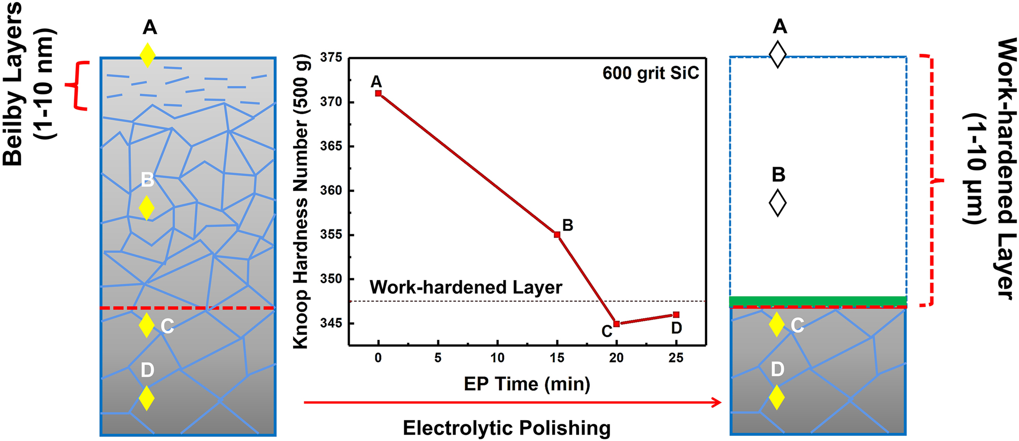
Schematic diagram of the surface stripping process in electrolytic polishing.
Electrolytic polishing creates a dense and thin passivation layer, significantly better than the passivation film formed by air and nitric acid. Lee and Lai (2003) and Awad et al. (2012) found that Fe dissolved before Cr and Ni, and the Cr content of the passivated film was significantly increased during the electrolytic polishing process (Figure 32), inferring that the main component of the film was Cr2O3, which can improve the corrosion resistance of stainless steel substantially.
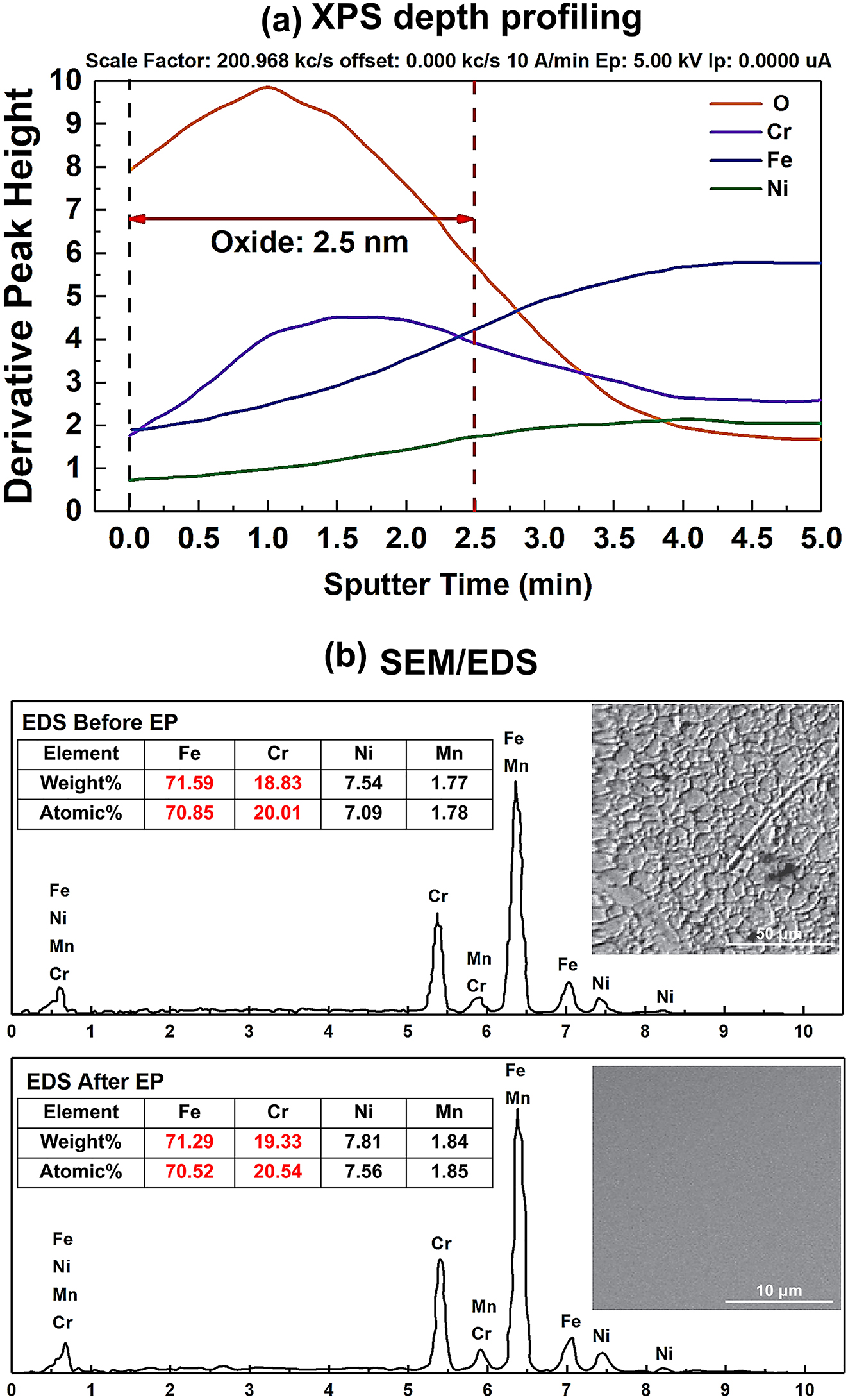
Characterisation of the surface composition of electrolytic polishing: (a) XPS depth profiling, (b) surface SEM/EDS characterisation (Awad et al. 2012; Lee and Lai 2003). Reprinted with permission; copyright 2012 Elsevier; reprinted with permission; copyright 2003 Elsevier.
3.2.3 Electrochemical buffing (ECB)
Baba and Sato (1990) proposed that mechanical and electrolytic polishing can create a finer surface, further reducing surface roughness and changing the surface stress state, known as electrochemical buffing (ECB). Figure 33 depicts the ECB technology can achieve lower surface roughness and can handle 316L ultra-high purity components to obtain a bright, contamination-free, micro-crack-free surface (Tsuji et al. 2017).
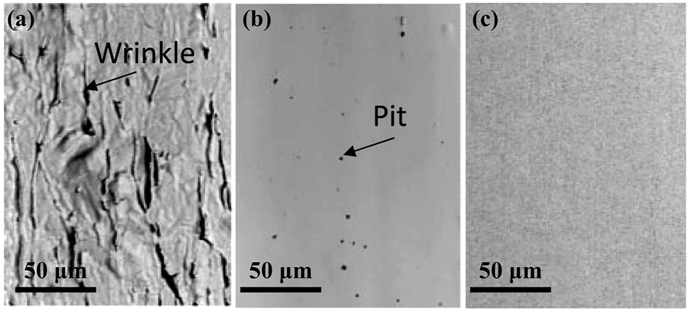
Surface morphology of different surface treatments: (a) bright annealing, (b) electrolytic polishing, (c) electrochemical buffing (Tsuji et al. 2017). Reprinted with permission; copyright 2017 Japan Society of Applied Physics.
ECB can significantly reduce surface roughness, change the metal surface’s stress state, and eliminate defects caused by cold working, as shown in Table 5.
Influence of ECB on surface stress variations.
| Serial no. | Treatment | X-directional stress (MPa) | Y-directional stress (MPa) |
|---|---|---|---|
| A-1 | Bending | +47.9 | +11 |
| A-2 | Bending + ECB | −32.0 | −35 |
| B-1 | Welding | +17.6 | +4 |
| B-2 | Welding + ECB | −28.4 | −18 |
-
+: tensile stress; −: compressive stress.
The ECB mechanisms was described by Baba and Sato (1990) and Tsui et al. (2007). During the electrolytic process, the metal surface dissolves, and a passivation film is subsequently formed. Due to the grinding of the abrasive particles, the passivation film is stripped from the surface bumps, leaving the bumps in a dissolved state again, thereby dissolving the metal. Figure 34 illustrates that the iterative electrochemical and mechanical processes between the workpiece and grinding edge shorten the polishing time and smooth the bumps on the metal surface, finally polishing the surface to a mirror finish. The average and maximum surface roughness is further reduced.
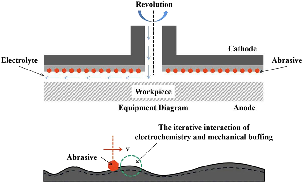
Equipment and mechanisms of ECB.
A distinct advantage of ECB over EP exists is that ECB creates a fine grain structure on the stainless steel surface due to the synergistic effect of electrolytic and micro polishing with viscoelastic abrasives. Shirai et al. (1996) and Ohmi et al. (1996) found that the α-phase appeared on the ECB-treated stainless steel surface, as shown in Figure 35. In addition, Baba and Sato (1990) revealed the appearance of an amorphous structure on the ECB surface via high-energy electron diffraction and that the amorphous structure positively affects corrosion resistance.
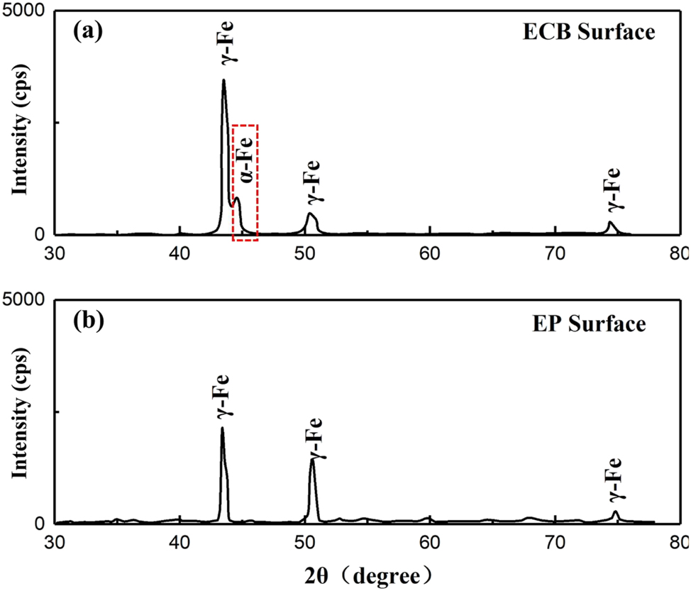
Structural differences between ECB and EP surface crystals: (a) ECB surface, (b) EP surface (Ohmi et al. 1996). Reprinted with permission; copyright 1996 American Vacuum Society.
3.3 Passivation and coating technology
With the continuous development of the semiconductor manufacturing industry, melting technology and surface polishing of stainless steel cannot meet the extremely corrosion-intensive application requirements, such as fluorine exhaust gas output piping (Maeno et al. 1992a,b; Miki et al. 1990) and ultra-high purity gas filters (Amari et al. 1999; Haider and Shadman 1989) etc. Therefore, excellent surface treatment of stainless steel is required to improve the surface properties, extend the service time, and ensure the cleanliness of gases and chambers. The surface treatment can be divided into two (1) preparation of a complete passivation film and (2) application of stainless steel surface coating.
3.3.1 Passivation of stainless steel
Stainless steel can form a passivation film in the atmosphere for excellent corrosion resistance (Zhao et al. 2020). The structural denseness of the passivation film, chemical composition, and other factors determine its corrosion resistance (Ge et al. 2003; Wang et al. 2019). Nowadays, certain methods make obtaining passivation film structures with excellent properties possible. The higher the percentage of Cr in the film’s chemical composition, the higher the corrosion resistance (Wallinder et al. 1998). In the semiconductor manufacturing industry, however, stainless steel has to meet corrosion resistance requirements and requires significant attention regarding moisture absorption and desorption (Tomari et al. 1990). This review highlights methods on improving passivation film performance (Table 6).
Passivation treatment methods.
| Serial no. | Methods | Process condition | References |
|---|---|---|---|
| 1 | Dry passivation treatment | High temperature treatment (350 °C–500 °C) in 20 % oxygen & argon (dew point temperature: −100 °C) for 4 h | Tomari et al. (1990), Tomari (1995, 1997) |
| 2 | Iron-free (low) passivation treatment | High temperature treatment (500 °C) with 100 ppm H2O in 10 % H2 & Ar gas for 1 h | Shirai et al. (1994, 1996, Ohmi et al. (1996, 1998) |
| 3 | Fluorinated passivation | Fluorination in 100 % fluorine gas followed by thermal modification in 100 % nitrogen gas, where the temperature range is 220 °C–400 °C for 10 min–60 min | Maeno and Nakagawa (1992), Miki and Maeno (1990), Miki et al. (1990) |
The passivation film of stainless steel is composed of Cr2O3 and Fe2O3. When the Cr percentage increases, the corrosion resistance improves significantly (Ohmi et al. 1998; Shirai et al. 1994). The reasons can be divided into two parts: (1) When the temperature is below 170 °C and above 400 °C, the Gibbs free energy change in Cr2O3 reacting with corrosion gases is significantly higher than Fe2O3, as shown in Figure 36a. The Cr2O3 stability in the corrosive gases environment is better. The higher Cr2O3 percentage in the film demonstrates the film’s better corrosion resistance. (2) The passivation film (Cr2O3) exhibits excellent moisture release properties, i.e., minimal moisture remains on the Cr2O3 after purging. Water molecule adsorption is an important factor affecting the corrosion rate; therefore, increasing the Cr2O3 percentage contributes to reducing the effect of the condensation water in accelerating corrosion.
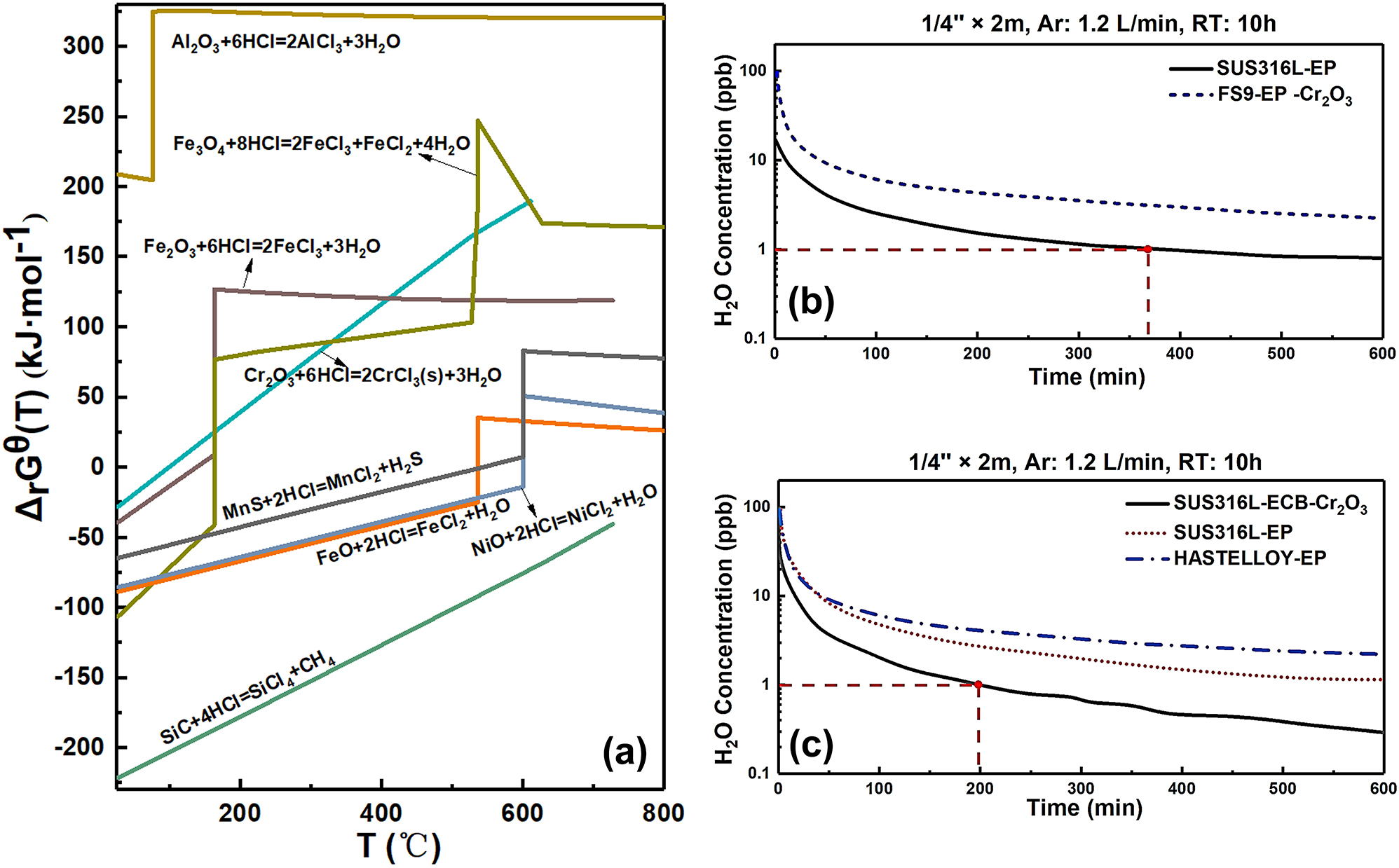
Moisture sensitivity of material composition: (a) curves of Gibbs free energy, (b, c) curves of moisture release of different specimens surfaces (Shirai et al. 1994). Reprinted with permission; copyright 1994 IEICE.
Tomari et al. (1990) suggested that obtaining excellent surface passivation films on 316L (EP) stainless steel was possible by dry passivation treatment. The passivation film’s ability to release moisture is significantly improved compared to 316L (EP), and the dry passivation treatment is strictly temperature dependent, with excellent hydrophobic properties achieved in the appropriate interval, as shown in Figure 37. In addition, the passivation film is exposed to 35 % HCl solution, and the corrosion resistance is evaluated by observing the hydrogen generation time. As shown in Figure 38, the material’s corrosion resistance increases significantly in the corresponding temperature interval, i.e., the lower the moisture concentration in dry passivation treatment, the better the film’s corrosion resistance. Composition analysis of passivation films prepared at different moisture concentrations indicated that at lower moisture concentrations, the Cr percentage in the passivation film is high; thus, the corrosion resistance is higher (Tomari 1995).
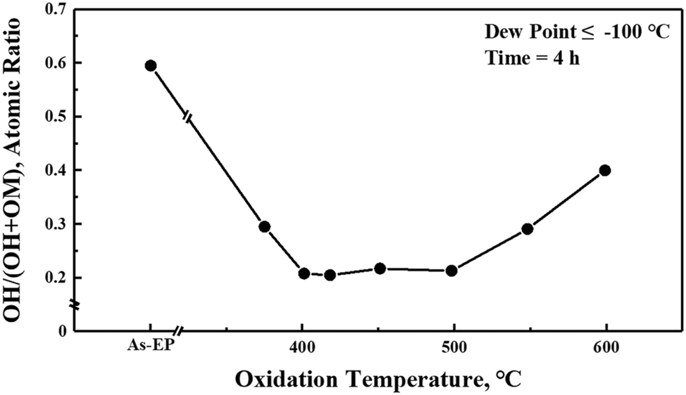
Curve of moisture adsorption capacity versus temperature (dry passivation treatment) (Tomari et al. 1990). Reprinted with permission; copyright 1990 Elsevier.
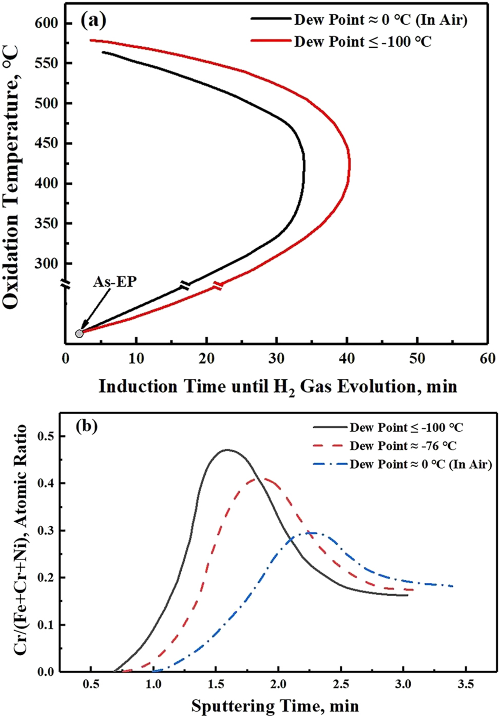
Effect of different moisture concentrations during preparation on the corrosion resistance of passivated films: (a) curves for hydrogen generation time, (b) curves for the percentage of chromium in passivation films prepared with different water concentrations during preparation (Tomari et al. 1990). Reprinted with permission; copyright 1990 Elsevier.
Therefore, the lower the moisture content of dry passivation treatment, the higher the Cr content of the prepared passivation film and the better the corrosion resistance. The decrease in corrosion resistance at excessively high temperatures is attributed to the microstructural changes caused by thermal ageing.
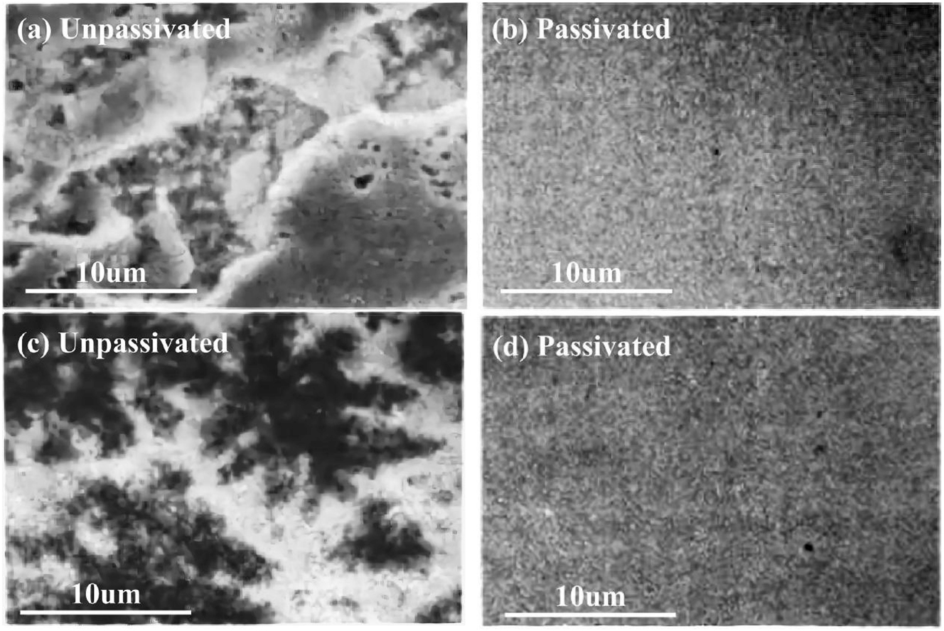
Shirai et al. (1996) and Ohmi et al. (1996) demonstrated the successful formation of passivation films without Fe elements on the ferritic stainless steel (FS9) and austenitic stainless steel (316L) surface. The percentage of Fe elemental on the surface is zero, and the chromium-to-oxygen ratio is 2:3 (Figure 39), suggesting that the passivation film composition is predominantly Cr2O3. Meanwhile, the Cr2O3 passivation film exhibits excellent corrosion resistance, superior to nickel-based alloys. Figure 40 shows no corrosion after 120 h of exposure to HBr (20 cc/min) gas at 120 °C.
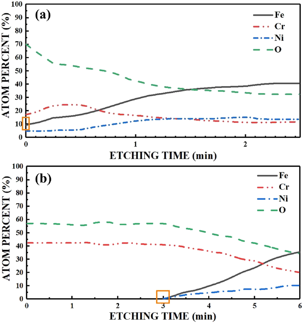
XPS depth profiles of iron-free passivation film: (a) 316L (EP), (b) Passivation (Cr2O3) (Ohmi et al. 1996). Reprinted with permission; copyright 1996 American Vacuum Society.
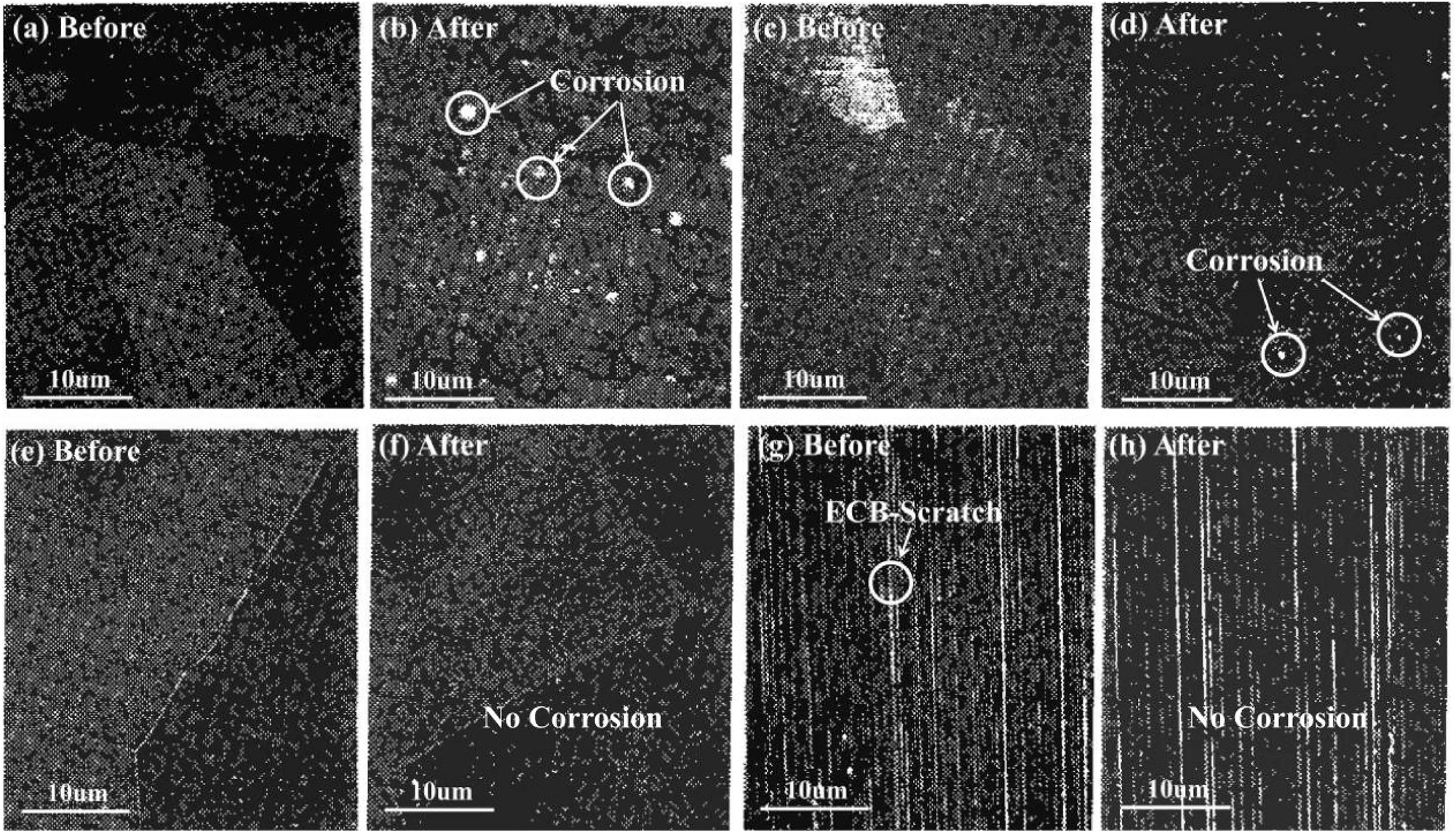
Corrosion morphology of stainless steel with different surface treatments after 120 h of exposure to HBr (20 cc/min) gas at 120 °C: (a, b) 316L-EP, (c, d) HASTELLOY-EP, (e, f) FS9-EP-Cr2O3, (g, h) 316L-ECB-Cr2O3 (Shirai et al. 1994). Reprinted with permission; copyright 1994 IEICE.
Stainless steel forms excellent passivation films by oxidation. Fluorinated passivation films can also be prepared using F2 (Maeno et al. 1992a,b; Miki et al. 1990). Fluorinated passivated films demonstrate excellent corrosion resistance. The equation for the reaction between F2 and stainless steel is as follows;
where the FexFy is a mixture of FeF2 and FeF3. Here, there is an excess of fluorine in the interstitial and lattice positions of the fluorinated film and between the fluorinated film and stainless steel. Since the solid-gas transition temperature of FeF3 is much lower than that of FeF2, the FexFy has a loose structure, unsatisfactory corrosion resistance and hydrophobic properties, requiring post-treatment. Transformation of FeF3 to FeF2 by surface modification is done according to the following equation;
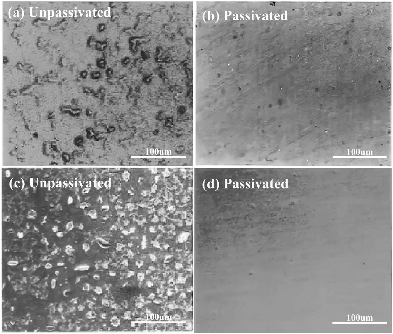
Miki et al. (1990) reported that when the modified fluorinated films were exposed to a high-pressure chlorine environment (Cl2, 490 kPa, 25 °C, 72 h) and a hydrogen fluoride environment containing moisture (HF: H2O: N2 = 5: 1: 94, 98 kPa, 25 °C, 72 h), no corrosion is observed (Figure 41).
Corrosion morphology of the fluorinated film: (a, b) Cl2, 490 kPa, 25 °C, 72 h, (c, d) HF: H2O: N2 = 5: 1: 94, 98 kPa, 25 °C, 72 h (Miki et al. 1990). Reprinted with permission; copyright 1990 Elsevier.
3.3.2 Coating technology of stainless steel
Nickel alloys exhibit excellent corrosion resistance but cannot be used widely due to their high expense. Therefore, nickel is deposited on the stainless steel surface in the semiconductor manufacturing industry by electroless plating for excellent corrosion resistance. Nowadays, the widest application of electroless nickel is the Ni–P coating. The electroless nickel plating allows a uniform coating on irregularly shaped workpieces, uniformly coating the entire surface and depositing into depressions and internal areas (Narayanan et al. 2006; Sarret et al. 2006).
Electroless Ni–P coatings’ microstructure and corrosion resistance depends primarily on phosphorus content (Shozib et al. 2022). The microstructure of low phosphorus coating comprises a mixture of amorphous and microcrystalline, with relatively high mechanical properties. High phosphorus coatings have high corrosion resistance due to their homogeneous amorphous microstructure; however, their mechanical properties are relatively weak (Gu et al. 2005; Sahoo and Das 2011). Electroless Ni–P coatings with 1–5 wt% phosphorus (low phosphorus) are crystalline, while electroless Ni–P coatings with 6–9 wt% phosphorus (medium phosphorus) are a mixture of crystalline and amorphous structures and electroless Ni–P coatings with 10–13 wt% phosphorus (high phosphorus) are amorphous. With the increase in phosphorus content, the structure of the coating changes gradually from crystalline to amorphous. The amorphous structure of nickel–phosphorus solid solution is extremely homogeneous, without any dislocations, twins, grain boundaries, and other defects. The surface oxide film also does not show faults and other defects (Shozib et al. 2022). The high phosphorus coating possesses an extremely high toughness that makes it difficult to fracture, while the non-crystalline surface oxide film is produced and repaired quickly once damaged. The oxide film is a phosphate film, preventing corrosion and therefore enhancing the corrosion resistance of the coating. However, this coating is susceptible to corrosion by strong oxidizing acids. The amorphous structure of nickel–phosphorus is initially deposited on grain boundaries and then slowly spreads in all directions, as shown in Figure 42, gradually forming a cellular morphology with time, densely and compactly aligned with each other (Guo et al. 2017).
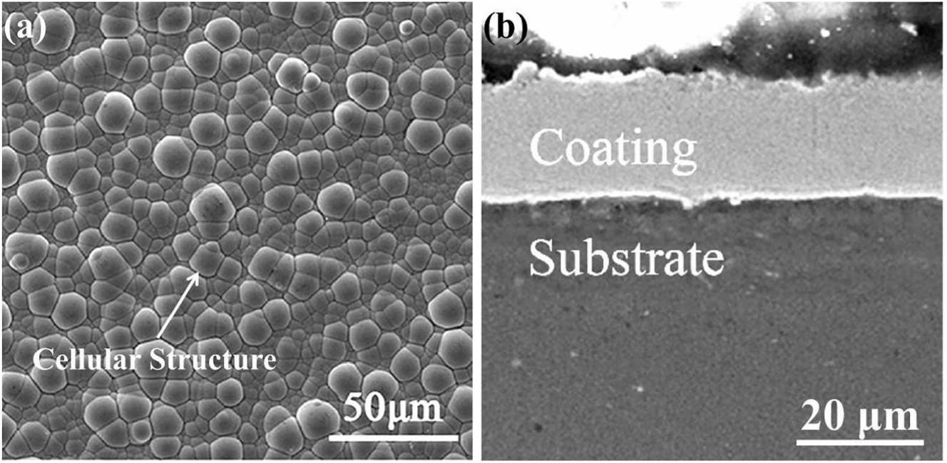
Morphology of electroless Ni–P: (a) surface, (b) cross-section (Guo et al. 2017). Reprinted with permission; copyright 2017 John Wiley and Sons.
Figure 43 shows unavoidable pores on the coating surface; therefore, the corrosion medium diffuses from the surface to the substrate through meandering pores. At this point, there is a potential difference between the coating and the substrate, with a larger cathode (coating) and a smaller anode (exposed substrate), resulting in an extremely rapid corrosion rate.
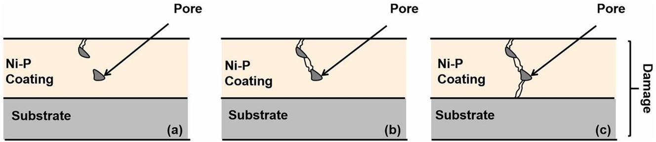
Schematic diagram of the corrosion failure mechanism of electroless Ni–P.
Electroless Ni–P is sensitive to temperature. When held at lower temperatures, the amorphous structure transforms from a higher energy sub-stable amorphous structure to a lower energy sub-stable amorphous structure, called structural relaxation. It can reduce the internal stress in the coating, increasing the hardness, precipitating hydrogen, reducing the porosity and improving corrosion resistance. At a higher temperature, the coating atoms gain enough energy, enhancing the diffusion ability, overcoming the potential barrier of amorphous transformation into crystals and generating a new crystal phase (Ni3P) crystal defects (grain boundaries and segregation), and reducing corrosion resistance (Georgiza et al. 2013; Zhang et al. 2008).
Electroless Ni–P can be applied on aluminium alloys, steel, and polymers, etc. (Shozib et al. 2022). However, even after the coating fails in the semiconductor manufacturing industry, stainless steel remains stable compared to other substrates. Therefore, considering safety, cost and semiconductor profit, stainless steel is a suitable substrate in the semiconductor manufacturing industry.
In semiconductor manufacturing, Ni–F coatings on stainless steel exhibit excellent corrosion resistance in fluorinated environments. Ni–F coatings are suitable in fluorinated gas environments. However, directly depositing Ni–F on stainless steel surfaces is not conducive; therefore, priority is given to the electroless Ni–P and subsequent modification by fluorination (Ohmi 1994).
Maeno et al. (1992a,b) described that the composition of the Ni–F coating is NiF2. In a fluorinated environment, the phosphorus in the Ni–P coating is oxidized by the fluorine gas to PF5. PF5 is volatile in a fluorinated environment and detaches from the coating, as shown in Figure 44, while the fluorine combines with nickel to form a stable NiF2 structure, according to the following reaction equation;
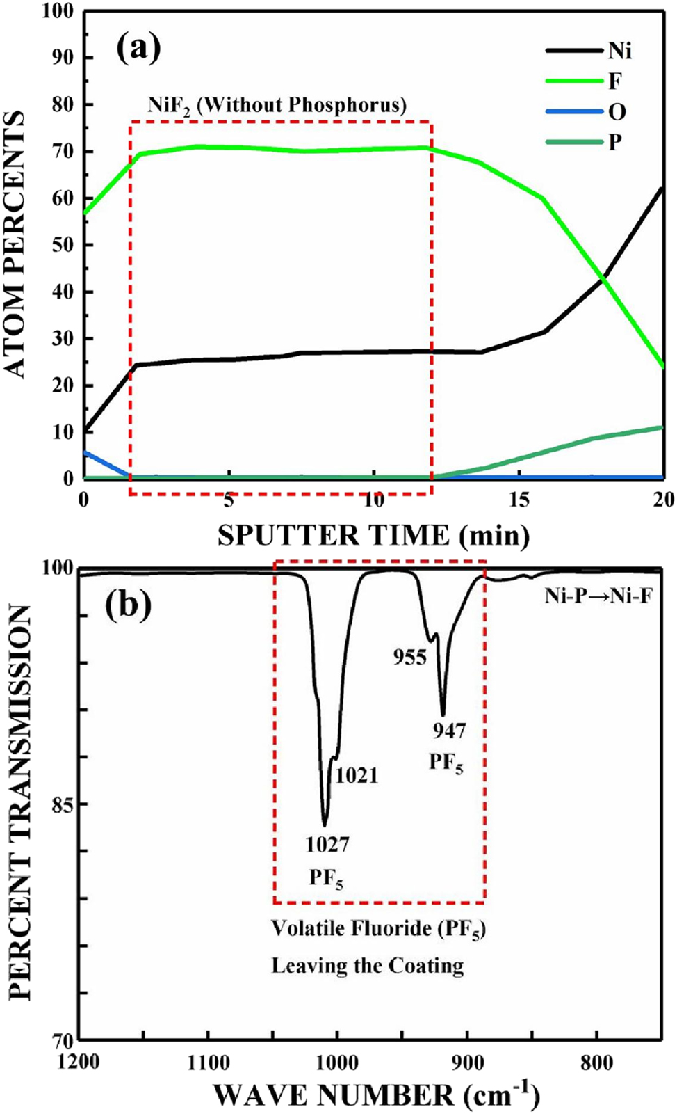
Conversion of phosphorus to fluorine in electroless Ni–P: (a) XPS depth profile, (b) FTIR spectroscopy (Maeno et al. 1992a,b). Reprinted with permission; copyright 1992 IOP Publishing.
The corrosion resistance of the coating substantially improves by fluorination. No corrosion is observed after exposure to high-pressure chlorine and wet HF gas (Figure 45).
Corrosion morphology of the Ni–F coating: (a, b) Cl2, 2 kg cm−2, 25 °C, 168 h, (c, d) HF: H2O: N2 = 5: 1: 94, 1 kg cm−2, 25 °C, 72 h (Maeno et al. 1992a,b). Reprinted with permission; copyright 1992 IOP Publishing.
4 Conclusions
This paper reviews the semiconductor manufacturing industry’s stainless steel corrosion mechanisms and anti-corrosion technologies. Stainless steel is used primarily in gas delivery systems, including components such as gas delivery pipelines, valves and filters, in ambient or low-temperature environments. The moisture adsorption and condensation in the gas delivery system are important factors in accelerating the corrosion of stainless steel. The moisture adsorption in the gas mixture is associated with partial pressure and temperature. In addition, the higher dew point temperature results in a greater tendency for moisture condensation. Stainless steel is also used for structural components in chambers, including gas phase epitaxy equipment, serving in high-temperature environments. Considering the thermal ageing and corrosion products’ phase state is necessary. Thermal ageing, mainly manifested by spinodal decomposition and carbide precipitation, creates Cr-depleted zones and sensitization, reducing corrosion resistance. The phase state of the corrosion product directly influences the particle release.
Anti-corrosion technologies in the semiconductor manufacturing industry are classified into three aspects. (1) purity of the material is improved by reducing stainless steel impurities and controlling the harmful elements’ contents, thus, increasing the corrosion resistance. Material can be purified by advanced metallurgical techniques (AOD/VIM/VAR). (2) Surface smoothing is achieved by polishing technology. Reducing surface roughness and surface undulations can effectively lower contaminants and moisture adsorption, enabling the stripping of inclusions, thus improving corrosion resistance. (3) Protection of stainless steel is achieved by preparing passivation films and coatings. Exclusive passivation films and coatings can be created for different gas environments to improve the material’s corrosion resistance.
5 Future perspective
5.1 Experimental equipment
The semiconductor manufacturing industry has had no in-situ corrosion and particle release equipment. Therefore, it is necessary to manufacture relevant equipment to simulate the service environment in the semiconductor manufacturing industry. Better corrosion experiments can be conducted with the assistance of this equipment.
5.2 Testing methods
Due to the trace amount of moisture in the semiconductor gas environment, corrosion is dominated by chemical reactions rather than electrochemical reactions, resulting in a very slow corrosion rate of stainless steel. Conventional accelerated methods, such as potentiodynamic polarization, can only be used in liquid environments, but cannot be used in semiconductor gas environments. Therefore, it is necessary to develop accelerated experimental methods to evaluate the materials’ corrosion resistance, such as controlling moisture content in the environment and preparing heat-aged samples in advance.
5.3 Basic data
The major attention is focused on the evaluation of stainless steel corrosion resistance in the semiconductor manufacturing industry, resulting in the lack of basic data about the corrosion mechanism of stainless steel, including thermodynamic and kinetic data. Thermodynamic data, including solid-gas transition threshold, moisture adsorption, Gibbs free energy, and dew point, can be obtained from theoretical computations and relevant software, while kinetic data, such as activation energy and reaction rate constant, can be derived through the first principle calculations and molecular dynamics.
5.4 Lifetime prediction models
Although lifetime prediction models for stainless steels have been comprehensively studied, developing new lifetime prediction models for unique environments in the semiconductor manufacturing industry is necessary. Both temperature and moisture content should be considered for such models. Based on the new life prediction model, maintenance and replacement periods for stainless steel can be developed.
5.5 Anti-corrosion technologies
Improving the corrosion resistance of stainless steel surface through nitriding technology has not been tried. Nitriding could improve the material’s corrosion resistance. It is necessary to strengthen the in-depth understanding of electrolytic polishing mechanisms to reveal the key factors affecting polishing performance. It is required to model anode dissolution and develop new polishing solutions to improve electrolytic polishing capacity and reduce economic costs. Finally, preparing passivation films with low moisture adsorption and high corrosion resistance can be attempted by chelate and alternating voltage passivation techniques. Preparing coatings with low porosity by supercritical fluid electroless plating techniques can also be attempted.
Funding source: Huawei Company, LiaoNing Revitalization Talents Program
Award Identifier / Grant number: XLYC2002071
Funding source: Key Laboratory of Preparation and Applications of Environmentally Friendly Materials (Jilin Normal University)
Funding source: Ministry of Education
Award Identifier / Grant number: 2020011
Funding source: Youth Program of the National Natural Science Foundation of China
Award Identifier / Grant number: 52001061
Funding source: Young Elite Scientist Sponsorship Program Cast
Award Identifier / Grant number: YESS20200139
Funding source: Fundamental Research Funds for the Central Universities
Award Identifier / Grant number: N2202016
Funding source: Huzhou Key Research and Development Program
Award Identifier / Grant number: 2023ZD2001
About the authors

Chaoran Ma received his M.Sc. Degree in Materials Science and Engineering in 2019 from China University of Petroleum. He is currently a Ph.D. student at Northeastern University, China. His research focuses on the corrosion and protection of stainless steel in semiconductor manufacturing industry. His area of expertise includes design of experiments, EIS, thermodynamic calculation. He has several journal publications and received some awards about corrosion.

Peng Zhou is a lecturer at Northeastern University, China. He obtained his Ph.D. in Materials Engineering from Pierre and Marie Curie University, France. His research focuses on design of corrosion-resistant magnesium alloy, chemical conversion film for magnesium alloy, passivation technology for stainless steel, rolling technology for stainless steel. He has published several high impact journals and received a lot of awards during his academic life.

Yang Zhao is currently an associate professor at Northeastern University, China. He obtained his Ph.D. in Materials Engineering from Harbin Engineering University, China. His research focuses on the corrosion of stainless steel in the petroleum industry. His area of expertise includes lifetime prediction, thermodynamic calculations, simulation, programming, surface modification. He has published several high-impact refereed journals and attended many conferences.

Tao Zhang is a professor and doctoral supervisor at Northeastern University, China. He obtained his Ph.D. from Institute of Metals, Chinese Academy of Sciences. His research areas include surface treatment technologies for magnesium alloys, corrosion and protection in the petroleum industry, and corrosion and protection in high-precision microchip manufacture. He has published 90 high-level scientific papers, 15 national invention patents, and 1 monograph.

Fuhui Wang is the chairman of the ninth and tenth sessions of the Council of the Chinese Society for Corrosion and Protection, and the director of the High Temperature Professional Committee. He is a professor and doctoral supervisor at Northeastern University, China. His research areas include the chemical stability of nanomaterials, high-temperature corrosion and protection of advanced materials, and surface modification of materials. He has published more than 350 papers in influential academic journals and conferences, with over 3000 citations and over 30 invention patents.
-
Research ethics: Not applicable.
-
Author contributions: Chaoran Ma: literature investigation, formal analysis, methodology, validation, visualization, writing – original draft. Zhuoyang Du: literature investigation, data collation. Xiaohan Wang: data analysis and calculation. Peng Zhou: resources, supervision, validation, writing – reviewing & editing. Yang Zhao: investigation, validation, visualization, supervision, writing – reviewing & editing. Yong Hua: conceptualization, writing – reviewing & editing. Cheng Su: writing – reviewing & editing. Tao Zhang: project administration, conceptualization, supervision, funding, acquisition, writing – reviewing & editing. Fuhui Wang: vonceptualization, supervision, funding acquisition.
-
Competing interests: The authors declare that they have no known competing financial interests or personal relationships that could have appeared to influence the work reported in this paper.
-
Research funding: The authors would express their gratitude for the financial support from Huawei Company, LiaoNing Revitalization Talents Program (no. XLYC2002071), the Key Laboratory of Preparation and Applications of Environmentally Friendly Materials (Jilin Normal University), Ministry of Education (2020011), the Youth Program of the National Natural Science Foundation of China (grant no. 52001061), the Young Elite Scientist Sponsorship Program Cast (grant no. YESS20200139), the Fundamental Research Funds for the Central Universities (grant no. N2202016) and Huzhou Key Research and Development Program (no. 2023ZD2001).
-
Data availability: Not applicable.
References
Accomazzo, M.A. and Grant, D.C. (1989). Particle retention and downstream cleanliness of point-of-use filters for semiconductor process gases. In: Particles in gases and liquids 1: detection. Characterization, and control. Springer US, Boston, pp. 223–233.10.1007/978-1-4613-0793-8_15Suche in Google Scholar
Ahn, J.H., Kang, K.T., and Ahn, K.H. (2008). Development and evaluation of differential pressure type mass flow controller for semiconductor fabrication processing. J. Semicond. Displ. Technol. 7: 29–34.Suche in Google Scholar
Alkire, R. and Cangellari, A. (1983). Formation of salt films during anodic metal dissolution in the presence of fluid flow. J. Electrochem. Soc. 130: 1252–1259, https://doi.org/10.1149/1.2119935.Suche in Google Scholar
Allahyari, A.A., Farhangi, H., and Hadavi, S.M.M. (2005). Investigation of aging heat treatment on microstructure and mechanical properties of 316L austenitic stainless steel weld metal. WIT Trans. Eng. Sci. 51: 1743–3522.Suche in Google Scholar
Aller, J., Ellingwood, K., Clark, B., and Gannon, P.E. (2015). The time and temperature dependence of AISI 316L corrosion in chlorosilane environments. ECS Trans. 66: 41–51, https://doi.org/10.1149/06618.0041ecst.Suche in Google Scholar
Aller, J., Ellingwood, K., Jacobson, N., and Cannon, P. (2016). High temperature chlorosilane corrosion of AISI 316L. J. Electrochem. Soc. 163: C452, https://doi.org/10.1149/2.0751608jes.Suche in Google Scholar
Amari, M., Funahashi, I., and Ohyashiki, Y. (1999). Twenty fourth IEEE/CPMT international electronics manufacturing technology symposium. October 19–19 1999: Compatibility of gas filters with HBr gas. IEEE, USA.Suche in Google Scholar
Askey, A., Lyon, S.B., Thompson, G.E., Johnson, J.B., Wood, G.C., Cooke, M., and Sage, P. (1993). The corrosion of iron and zinc by atmospheric hydrogen chloride. Corros. Sci. 34: 233–247, https://doi.org/10.1016/0010-938x(93)90004-z.Suche in Google Scholar
Awad, A.M., Ghazy, E.A., El-Enin, S.A., and Mahmoud, M.G. (2012). Electropolishing of AISI-304 stainless steel for protection against SRB biofilm. Surf. Coat. Tech. 206: 3165–3172, https://doi.org/10.1016/j.surfcoat.2011.11.046.Suche in Google Scholar
Baba, Y. and Sato, K. (1990). Super mirror-flat finishing of metal surfaces by electrochemical buffing. Hyomen Kagaku 11: 368–374, https://doi.org/10.1380/jsssj.11.368.Suche in Google Scholar
Beck, T.R. (1982). Formation of salt films during passivation of iron. J. Electrochem. Soc. 129: 2412–2418, https://doi.org/10.1149/1.2123558.Suche in Google Scholar
Berg, R.F. (2014). Hydrogen traps in the outgassing model of a stainless steel vacuum chamber. J. Vac. Sci. Technol. A 32: 031604, https://doi.org/10.1116/1.4869962.Suche in Google Scholar
Block-Bolten, A. and Eagar, T.W. (1984). Metal vaporization from weld pools. Metall. Mater. Trans. B 15: 461–469, https://doi.org/10.1007/bf02657376.Suche in Google Scholar
Chandra, K., Kain, V., Bhutani, V., Raja, V.S., Tewari, R., Dey, G.K., and Chakravartty, J.K. (2012). Low temperature thermal aging of austenitic stainless steel welds: kinetics and effects on mechanical properties. Mater. Sci. Eng. A-Struct. 534: 163–175, https://doi.org/10.1016/j.msea.2011.11.055.Suche in Google Scholar
Chung, H.M. and Chopra, O.K. (1986). Proceedings of the 2nd international symposium on environmental degradation of materials in nuclear power systems-water reactors, September 09–09, 1986: Microstructures of cast-duplex stainless steel after long-term aging. American Nuclear Society, Monterey.Suche in Google Scholar
Cleslak, M.J., Ritter, A.M., and Savage, W.F. (1982). Solidification cracking and analytical electron microscope of austenite stainless steel weld metals. Weld. J. 61: 1–8.Suche in Google Scholar
Collins, S.R. (1997). 39th mechanical working and steel processing conference, 1997: Stainless steel for semiconductor applications. Iron & Steel Soc of AIME, Warrendale.Suche in Google Scholar
Cui, Y. and Lundin, C.D. (2005). Evaluation of initial corrosion location in E316L austenitic stainless steel weld metals. Mater. Lett. 59: 1542–1546, https://doi.org/10.1016/j.matlet.2005.01.018.Suche in Google Scholar
Cui, Y. and Lundin, C.D. (2007). Austenite-preferential corrosion attack in 316 austenitic stainless steel weld metals. Mater. Des. 28: 324–328, https://doi.org/10.1016/j.matdes.2005.05.022.Suche in Google Scholar
David, S.A., Vitek, J.M., and Alexander, D.J. (1996). Embrittlement of austenitic stainless steel welds. J. Nondestruct. Eval. 15: 129–136, https://doi.org/10.1007/bf00732040.Suche in Google Scholar
Davidson, P.A., He, X., and Lowe, A.J. (2000). Flow transitions in vacuum arc remelting. Mater. Sci. Tech-Lond. 16: 699–711, https://doi.org/10.1179/026708300101508306.Suche in Google Scholar
Ding, R., Blanpain, B., Jones, P.T., and Wollants, P. (2000). Modeling of the vacuum oxygen decarburization refining process. Metall. Mater. Trans. B 31: 197–206, https://doi.org/10.1007/s11663-000-0145-5.Suche in Google Scholar
Ding, X.P., Liu, X., He, Y.L., Fu, R.Y., and Li, L. (2009). Evolution of precipitation phase during aging treatment in 316L austenitic stainless steel. Chinese J. Mater. Res. 23: 269–274.Suche in Google Scholar
Dylla, H.F., Manos, D.M., and Lamarche, P.H. (1993). Correlation of outgassing of stainless steel and aluminum with various surface treatments. J. Vac. Sci. Technol. A 11: 2623–2636, https://doi.org/10.1116/1.578617.Suche in Google Scholar
Eklund, G.S. (1974). Initiation of pitting at sulfide inclusions in stainless steel. J. Electrochem. Soc. 121: 467–473, https://doi.org/10.1149/1.2401840.Suche in Google Scholar
Elmer, J.W., Allen, S.M., and Eagar, T.W. (1989). Microstructural development during solidification of stainless steel alloys. Metall. Mater. Trans. A 20: 2117–2131, https://doi.org/10.1007/bf02650298.Suche in Google Scholar
Fine, S.M., Rynders, R.M., and Stets, J.R. (1995). The role of moisture in the corrosion of HBr gas distribution systems. J. Electrochem. Soc. 142: 1286–1293, https://doi.org/10.1149/1.2044165.Suche in Google Scholar
Frenzel, J., Zhang, Z., Neuking, K., and Eggeler, G. (2004). High quality vacuum induction melting of small quantities of NiTi shape memory alloys in graphite crucibles. J. Alloy. Compd. 385: 214–223, https://doi.org/10.1016/j.jallcom.2004.05.002.Suche in Google Scholar
Fuertes, N., Bengtsson, V., Pettersson, R., and Rohwerder, M. (2017). Use of SVET to evaluate corrosion resistance of heat tinted stainless steel welds and effect of post‐weld cleaning. Mater. Corros. 68: 7–19, https://doi.org/10.1002/maco.201609048.Suche in Google Scholar
Ge, H.H., Zhou, G.D., and Wu, W.Q. (2003). Passivation model of 316 stainless steel in simulated cooling water and the effect of sulfide on the passive film. Appl. Surf. Sci. 211: 321–334, https://doi.org/10.1016/s0169-4332(03)00355-6.Suche in Google Scholar
Georgiza, E., Novakovic, J., and Vassiliou, P. (2013). Characterization and corrosion resistance of duplex electroless Ni–P composite coatings on magnesium alloy. Surf. Coat. Tech. 232: 432–439, https://doi.org/10.1016/j.surfcoat.2013.05.047.Suche in Google Scholar
Gill, T.P.S., Vijayalkshmi, M., Rodriguez, P., and Padmanabhan, K.A. (1989). On microstructure-property correlation of thermally aged type 316L stainless steel weld metal. Metall. Mater. Trans. A 20: 1115–1124, https://doi.org/10.1007/bf02650146.Suche in Google Scholar
Grimm, R.D. and Landolt, D. (1994). Salt films formed during mass transport controlled dissolution of iron-chromium alloys in concentrated chloride media. Corros. Sci. 36: 1847–1868, https://doi.org/10.1016/0010-938x(94)90023-x.Suche in Google Scholar
Grimm, R.D., West, A.C., and Landolt, D. (1992). AC impedance study of anodically formed salt films on iron in chloride solution. J. Electrochem. Soc. 139: 1622–1629, https://doi.org/10.1149/1.2069467.Suche in Google Scholar
Gu, C., Lian, J., Li, G., Niu, L., and Jiang, Z. (2005). High corrosion-resistant Ni–P/Ni/Ni–P multilayer coatings on steel. Surf. Coat. Tech. 197: 61–67, https://doi.org/10.1016/j.surfcoat.2004.11.004.Suche in Google Scholar
Guo, S.Q., Hou, L.F., Guo, C.L., and Wei, Y.H. (2017). Characteristics and corrosion behavior of nickel‐phosphorus coatings deposited by a simplified bath. Mater. Corros. 68: 468–475, https://doi.org/10.1002/maco.201609155.Suche in Google Scholar
Haider, A. and Shadman, F. (1989). Ninth IEEE/CHMT international symposium on electronic manufacturing technology, February 12–17, 1989: desorption of moisture from stainless steel tubes and ceramic filters in high purity gas distribution systems. IEEE, USA.Suche in Google Scholar
Hattori, T., Takagi, H., Boireau, A., Chevrel, H., Ozawa, E., and Friedt, J.M. (1994). Optimized welding of stainless steel tubings for corrosion free exposure to HBr gas. Jpn. J. Appl. Phys. 33: 2100–2110, https://doi.org/10.1143/jjap.33.2100.Suche in Google Scholar
He, H., Zhang, T., Zhao, C., Hou, K., Meng, G., Shao, Y., and Wang, F. (2009). Effect of alternating voltage passivation on the corrosion resistance of duplex stainless steel. J. Appl. Electrochem. 39: 737–745, https://doi.org/10.1007/s10800-008-9718-9.Suche in Google Scholar
He, Y. and Xing, Z. (2019). Investigations on the microstructure, mechanical properties and corrosion resistance of SUS 304 austenitic stainless steel welded joints by pulsed current gas tungsten arc welding. Mater. Res. Express 6: 088001, https://doi.org/10.1088/2053-1591/ab1b85.Suche in Google Scholar
Hernando, M., Núñez, P.J., García, E., and Trujillo, R. (2012). Effect of electrolyte on the surface smoothness obtained by electropolishing of stainless steel. Mater. Sci. Forum 713: 55–60, https://doi.org/10.4028/www.scientific.net/msf.713.55.Suche in Google Scholar
Hickling, A. and Higgins, J.K. (1952). The rate-determining stage in the anodic dissolution of metals. Trans. Inst. Met. Finish. 29: 274–301, https://doi.org/10.1080/00202967.1952.11869604.Suche in Google Scholar
Hirata, K. and Esashi, M. (2002). Stainless steel-based integrated mass-flow controller for reactive and corrosive gases. Sensor. Actuat. A-Phys. 97: 33–38, https://doi.org/10.1016/s0924-4247(01)00806-8.Suche in Google Scholar
Hong, H.U., Rho, B.S., and Nam, S.W. (2002). A study on the crack initiation and growth from δ-ferrite/γ phase interface under continuous fatigue and creep-fatigue conditions in type 304L stainless steels. Int. J. Fatigue 24: 1063–1070, https://doi.org/10.1016/s0142-1123(02)00019-1.Suche in Google Scholar
Hu, X., Jarnerud, T., Karasev, A., Jonsson, P.G., and Wang, C. (2020). Utilization of fly ash and waste lime from pulp and paper mills in the argon oxygen decarburization process. J. Clean Prod. 261: 121182, https://doi.org/10.1016/j.jclepro.2020.121182.Suche in Google Scholar
Ihara, Y., Ohgame, H., Sakiyama, K., and Hashimoto, K. (1981). The corrosion behaviour of iron in hydrogen chloride gas and gas mixtures of hydrogen chloride and oxygen at high temperatures. Corros. Sci. 21: 805–817, https://doi.org/10.1016/0010-938x(81)90023-8.Suche in Google Scholar
Ihara, Y., Ohgame, H., Sakiyama, K., and Hashimoto, K. (1982a). The corrosion behaviour of nickel in hydrogen chloride gas and gas mixtures of hydrogen chloride and oxygen at high temperatures. Corros. Sci. 22: 901–912, https://doi.org/10.1016/0010-938x(82)90060-9.Suche in Google Scholar
Ihara, Y., Ohgame, H., Sakiyama, K., and Hashimoto, K. (1982b). The corrosion behavior of Fe–Ni alloys in hydrogen chloride gas and gas mixtures of hydrogen chloride and oxygen at high temperatures. Trans. Japan Inst. Met. 23: 682–692, https://doi.org/10.2320/matertrans1960.23.682.Suche in Google Scholar
Ihara, Y., Ohgame, H., Sakiyama, K., and Hashimoto, K. (1983). The corrosion behaviour of chromium in hydrogen chloride gas and gas mixtures of hydrogen chloride and oxygen at high temperatures. Corros. Sci. 23: 167–181, https://doi.org/10.1016/0010-938x(83)90114-2.Suche in Google Scholar
Jeong, C., Kong, B.S., Shin, J.H., Chen, J., Xiao, Q., and Jang, C. (2022). Evaluation of thermal aging activation energies based on multi-scale mechanical property tests for an austenitic stainless steel weld beads. Mater. Sci. Eng. A-Struct. 835: 142629, https://doi.org/10.1016/j.msea.2022.142629.Suche in Google Scholar
Kadonaga, T. (1992). Production technology of electro-polished stainless steel pipe for ultra-pure gas supply system in semiconductor production process. Tetsu-to-Hagane 78: 1–9.Suche in Google Scholar
Kaneko, S. and Sato, Y. (1990). Electropolishing and chemical polishing for stainless steel. J. Surf. Finish. Soc. Jpn. 41: 203–206, https://doi.org/10.4139/sfj.41.203.Suche in Google Scholar
Kiang, Y.H. (1981). Predicting dew points of acid gases. Chem. Eng. 188: 127–128.Suche in Google Scholar
Kim, D., Kim, K., Chung, W., and Shin, B. (2022). Effect of the plating time on nickel electroless coating properties deposited on the super duplex stainless steel UNS S 32750. Int. J. Electrochem. Sci. 17: 220630, https://doi.org/10.20964/2022.06.19.Suche in Google Scholar
Kong, B.S., Shin, J.H., Jeong, C., Jang, C., and Kang, S.S. (2023). Stability and strengthening effect of aging induced-nanofeatures in δ-ferrite in an austenitic stainless-steel weld. J. Mater. Res. Technol. 23: 4990–5003, https://doi.org/10.1016/j.jmrt.2023.02.112.Suche in Google Scholar
Krawiec, H., Vignal, V., Heintz, O., and Oltra, R. (2006). Influence of the dissolution of MnS inclusions under free corrosion and potentiostatic conditions on the composition of passive films and the electrochemical behaviour of stainless steels. Electrochim. Acta 51: 3235–3243, https://doi.org/10.1016/j.electacta.2005.09.015.Suche in Google Scholar
Krishnan, S. and Laparra, O. (1997). Contamination issues in gas delivery for semiconductor processing. IEEE Trans. Semiconduct. Maunf. 10: 273–278, https://doi.org/10.1109/66.572082.Suche in Google Scholar
Kumagai, H.Y. (1990). Hazardous gas handling in semiconductor processing. J. Vac. Sci. Technol. A 8: 2865–2873, https://doi.org/10.1116/1.576640.Suche in Google Scholar
Kumar, V., Pradeep, J., Dhakad, S., Shekhar, H., Singh, S., and Kumar, S. (2015). Analysis of the effect of sensitization on austenitic stainless steel 304L welded by GTAW process. J. Technol. Innov. Res. 14: 1–121.Suche in Google Scholar
Łabanowski, J. and Głowacka, M. (2011). Heat tint colours on stainless steel and welded joints. Wel. Int. 25: 509–512, https://doi.org/10.1080/09507116.2010.540837.Suche in Google Scholar
Laly, S., Nakagawa, K., Kimijima, T., Taguchi, S., Ikeda, T., and Hasaka, S. (1996). Determination of particle-bound metallic impurities in semiconductor grade gases. I. Silane. Anal. Chem. 68: 4312–4315, https://doi.org/10.1021/ac960428+.10.1021/ac960428+Suche in Google Scholar
Landolt, D. (1987). Fundamental aspects of electropolishing. Electrochim. Acta 32: 1–11, https://doi.org/10.1016/0013-4686(87)87001-9.Suche in Google Scholar
Lee, E.S. (2000). Machining characteristics of the electropolishing of stainless steel (STS316L). Int. J. Adv. Manuf. Tech. 16: 591–599, https://doi.org/10.1007/s001700070049.Suche in Google Scholar
Lee, H.J., Kong, B.S., Subramanian, G.O., Heo, J., Jang, C., and Lee, K.S. (2018). Evaluation of thermal aging of δ-ferrite in austenitic stainless steel weld using nanopillar compression test. Scripta Mater. 155: 32–36, https://doi.org/10.1016/j.scriptamat.2018.06.016.Suche in Google Scholar
Lee, S.J. and Lai, J.J. (2003). The effects of electropolishing (EP) process parameters on corrosion resistance of 316L stainless steel. J. Mater. Process. Tech. 140: 206–210, https://doi.org/10.1016/s0924-0136(03)00785-4.Suche in Google Scholar
Lequien, F. and Moine, G. (2021). Corrosion of a 316L stainless steel in a gaseous environment polluted with HCl: mechanism. Mater. Corros. 72: 1–12, https://doi.org/10.1002/maco.202011883.Suche in Google Scholar
Li, G.W., Zhao, F., and Jing, T.A. (2005). Research on electropolishing of stainless steel. Electroplat. Pollut. Control 142: 27–29.Suche in Google Scholar
Li, S.L. (2014). Study on the heat treatment organization and properties of 316LN stainless steel, Ph.D. thesis. Nanchang, Nanchang University of Aeronautics.Suche in Google Scholar
Li, X., Chang, L., Liu, C., Leng, B., Ye, X., Han, F., and Yang, X. (2021a). Effect of thermal aging on corrosion behavior of type 316H stainless steel in molten chloride salt. Corros. Sci. 191: 109784, https://doi.org/10.1016/j.corsci.2021.109784.Suche in Google Scholar
Li, X., Gao, F., Jiao, J., Cao, G., Wang, Y., and Liu, Z. (2021b). Influences of cooling rates on delta ferrite of nuclear power 316H austenitic stainless steel. Mater. Charact. 174: 111029, https://doi.org/10.1016/j.matchar.2021.111029.Suche in Google Scholar
Li, Y., Yu, Z., Xue, W., and Leng, J. (2008). The electrolytic polishing study of the stainless steel foil (SUS 304). Int. Symp. Photoelectron. Detect. Imag. 6622: 585–591.10.1117/12.790925Suche in Google Scholar
Lim, Y.S., Kim, J.S., Ahn, S.J., Kwon, H.S., and Katada, Y. (2001). The influences of microstructure and nitrogen alloying on pitting corrosion of type 316L and 20wt.% Mn-substituted type 316L stainless steels. Corros. Sci. 43: 53–68, https://doi.org/10.1016/s0010-938x(00)00074-3.Suche in Google Scholar
Lin, X., Peng, Q., Han, E.H., and Ke, W. (2019). Assessment of thermal aging of austenitic stainless steel weld metal by using the double loop electrochemical potentiokinetic reactivation technique. Corrosion 75: 377–388, https://doi.org/10.5006/2902.Suche in Google Scholar
Liu, J., Zhang, T., Meng, G., Shao, Y., and Wang, F. (2015). Effect of pitting nucleation on critical pitting temperature of 316L stainless steel by nitric acid passivation. Corros. Sci. 91: 232–244, https://doi.org/10.1016/j.corsci.2014.11.018.Suche in Google Scholar
Lowery, P. and Roll, D. (1998). Comparing the characteristics of surface-passivated and electropolished 316L stainless steel. Micro-Santa Monic 16: 43–50.Suche in Google Scholar
Lu, W.F., Huang, J.Y., Yung, T.Y., Chen, T.C., and Tsai, K.C. (2020). Effects of dendrite axis and fusion boundary on stress corrosion cracking of ER308L/SS304L welds in a high-temperature water environment. Int. J. Pres. Ves. Pip. 179: 103940, https://doi.org/10.1016/j.ijpvp.2019.103940.Suche in Google Scholar
Łyczkowska-Widłak, E., Lochyński, P., and Nawrat, G. (2020). Electrochemical polishing of austenitic stainless steels. Materials 13: 2557–2572, https://doi.org/10.3390/ma13112557.Suche in Google Scholar PubMed PubMed Central
Maeno, M., Hirayama, R., Izumi, H., Miki, N., Chiba, K., Mikasa, Y., Matsushita, H., and Ohmi, T. (1992a). Fluorine passivation of metal alloy surface with volatile reaction enhanced mechanism. J. Electrochem. Soc. 139: 1865, https://doi.org/10.1149/1.2069513.Suche in Google Scholar
Maeno, M., Nakagawa, Y., Miki, N., and Ohmi, T. (1992b). Optimization of fluorine passivation of stainless steel surfaces. IEEE Trans. Semiconduct. Maunf. 5: 107–113, https://doi.org/10.1109/66.136271.Suche in Google Scholar
Magaino, S., Matlosz, M., and Landolt, D. (1993). An impedance study of stainless steel electropolishing. J. Electrochem. Soc. 140: 1365–1373, https://doi.org/10.1149/1.2221562.Suche in Google Scholar
Miki, N., Maeno, M., Maruhashi, K., Nakagawa, Y., and Ohmi, T. (1990). Fluorine passivation of stainless steel. Corros. Sci. 31: 69–74, https://doi.org/10.1016/0010-938x(90)90092-j.Suche in Google Scholar
Miyazaki, J., Kajiyama, T., and Matsumoto, K. (1996). Ultra high purity hydrogen gas supply system with liquid hydrogen. Int. J. Hydrogen Energy 21: 335–341, https://doi.org/10.1016/0360-3199(95)00100-x.Suche in Google Scholar
Mizushima, S. (2007). The improvement of the adsorption characteristics of stainless steel surfaces by sputter-deposited films. Metrologia 44: 161–164, https://doi.org/10.1088/0026-1394/44/2/007.Suche in Google Scholar
Mohan, S., Kanagaraj, D., Sindhuja, R., Vijayakshmi, S., and Renganathan, N.G. (2001). Electropolishing of stainless steel—a review. Trans. Inst. Met. Finish. 79: 140–142, https://doi.org/10.1080/00202967.2001.11871382.Suche in Google Scholar
Narayanan, T.S., Baskaran, I., Krishnaveni, K., and Parthiban, S. (2006). Deposition of electroless Ni–P graded coatings and evaluation of their corrosion resistance. Surf. Coat. Tech. 200: 3438–3445, https://doi.org/10.1016/j.surfcoat.2004.10.014.Suche in Google Scholar
Nemanic, V. and Setina, J. (2000). Experiments with a thin-walled stainless-steel vacuum chamber. J. Vac. Sci. Technol. A 18: 1789–1793, https://doi.org/10.1116/1.582425.Suche in Google Scholar
Ohmi, T. (1994). Cr2O3 and NiF2 passivation technology of metal surface. J. Surf. Finish. Soc. Jpn. 45: 26–31, https://doi.org/10.4139/sfj.45.26.Suche in Google Scholar
Ohmi, T., Nakagawa, Y., Nakamura, M., Ohki, A., and Koyama, T. (1996). Formation of chromium oxide on 316L austenitic stainless steel. J. Vac. Sci. Technol. A 14: 2505–2510, https://doi.org/10.1116/1.580010.Suche in Google Scholar
Ohmi, T., Yoshida, M., Matudaira, Y., Shirai, Y., Nakamura, O., Gozyuki, M., and Hashimoto, Y. (1998). Development of a stainless steel tube resistant to corrosive Cl2 gas for use in semiconductor manufacturing. J. Vac. Sci. Technol. B 16: 2789–2795, https://doi.org/10.1116/1.590273.Suche in Google Scholar
Otubo, J., Rigo, O.D., Neto, C.M., and Mei, P.R. (2006). The effects of vacuum induction melting and electron beam melting techniques on the purity of NiTi shape memory alloys. Mat. Sci. Eng. A-Struct. 438: 679–682, https://doi.org/10.1016/j.msea.2006.02.171.Suche in Google Scholar
Park, J.O., Suter, T., and Bohn, H. (2003). Role of manganese sulfide inclusions on pit initiation of super austenitic stainless steels. Corros. Sci. 59: 59–67, https://doi.org/10.5006/1.3277537.Suche in Google Scholar
Pumphrey, P.H. and Akhurst, K.N. (1990). Aging kinetics of CF3 cast stainless steel in temperature range 300–400 °C. Mater. Sci. Tech.-Lond. 6: 211–220, https://doi.org/10.1179/mst.1990.6.3.211.Suche in Google Scholar
Russell, P. and Newman, J. (1986). Anodic dissolution of iron in acidic sulfate electrolytes: I. Formation and growth of a porous salt film. J. Electrochem. Soc. 133: 59–69, https://doi.org/10.1149/1.2108541.Suche in Google Scholar
Sahoo, P. and Das, S.K. (2011). Tribology of electroless nickel coatings–a review. Mater. Des. 32: 1760–1775, https://doi.org/10.1016/j.matdes.2010.11.013.Suche in Google Scholar
Sahu, J.K., Krupp, U., Ghosh, R.N., and Christ, H.J. (2009). Effect of 475 °C embrittlement on the mechanical properties of duplex stainless steel. Mat. Sci. Eng. A. 508: 1–14, https://doi.org/10.1016/j.msea.2009.01.039.Suche in Google Scholar
Saito, K. (1997). Outgassing from vacuum materials. J. Vac. Soc. Jpn. 40: 835–840, https://doi.org/10.3131/jvsj.40.835.Suche in Google Scholar
Sarret, M., Müller, C., and Amell, A. (2006). Electroless Ni–P micro-and nano-composite coatings. Surf. Coat. Tech. 201: 389–395, https://doi.org/10.1016/j.surfcoat.2005.11.127.Suche in Google Scholar
Savadkouhi, J. (2003). Advanced semiconductor manufacturing conference and workshop, March 31–April 01, 2003: Reliability considerations for gas delivery components. IEEE, Germany.Suche in Google Scholar
Sefa, M., Fedchak, J.A., and Scherschligt, J. (2017). Investigations of medium-temperature heat treatments to achieve low outgassing rates in stainless steel ultrahigh vacuum chambers. J. Vac. Sci. Technol. A 35: 041601, https://doi.org/10.1116/1.4983211.Suche in Google Scholar PubMed PubMed Central
Shirai, Y., Miyoshi, S., Kojima, T., and Ohmi, T. (1994). Anti-corrosive and anti-catalytic Cr2O3 treated gas tubing system. Int. Symp. Semicond. Manuf. 18: 217–218.10.1109/ISSM.1994.729461Suche in Google Scholar
Shirai, Y., Narazaki, M., and Ohmi, T. (1996). Cr2O3 passivated gas tubing system for specialty gases. IEICE Trans. Electron. 79: 385–391.Suche in Google Scholar
Shozib, I.A., Ahmad, A., Abdul-Rani, A.M., Beheshti, M., and Aliyu, A.A.A. (2022). A review on the corrosion resistance of electroless Ni–P based composite coatings and electrochemical corrosion testing methods. Corros. Rev. 40: 1–37, https://doi.org/10.1515/corrrev-2020-0091.Suche in Google Scholar
Siefering, K.L. and Whitlock, W.H. (1994). Measurement and modeling of moisture adsorption properties of 316 stainless steel tubing samples. J. Vac. Sci. Technol. A 12: 2685–2691, https://doi.org/10.1116/1.579089.Suche in Google Scholar
Smudde, G.H., Bailey, W.I., Felker, B.S., George, M.A., and Langan, J.G. (1995). Materials selection for HBr service. Corros. Sci. 37: 1931–1946, https://doi.org/10.1016/0010-938x(95)00075-u.Suche in Google Scholar
Speight, J. (2005). Lange’s handbook of chemistry. McGraw-Hill Education, America.Suche in Google Scholar
Sutow, E.J. (1980). The influence of electropolishing on the corrosion resistance of 316L stainless steel. J. Biomed. Mater. Res. 14: 587–595, https://doi.org/10.1002/jbm.820140505.Suche in Google Scholar PubMed
Szummer, A., Janik-Czachor, M., and Hofmann, S. (1993). Discontinuity of the passivating film at nonmetallic inclusions in stainless steels. Mater. Chem. Phys. 34: 181–183, https://doi.org/10.1016/0254-0584(93)90210-d.Suche in Google Scholar
Tan, Y., Ren, S., Shi, S., Wen, S., Jiang, D., Dong, W., Ji, M., and Sun, S. (2014). Removal of aluminum and calcium in multicrystalline silicon by vacuum induction melting and directional solidification. Vacuum 99: 272–276, https://doi.org/10.1016/j.vacuum.2013.06.015.Suche in Google Scholar
Tomari, H. (1995). Passive film and corrosion resistance of electropolished stainless steel pipe for semiconductor processing. Mater. Jpn. 34: 1062–1067, https://doi.org/10.2320/materia.34.1062.Suche in Google Scholar
Tomari, H. (1997). The slight degree of corrosion of stainless steel for semiconductor manufacturing plants. Zairyo-to-Kankyo 46: 202–209, https://doi.org/10.3323/jcorr1991.46.202.Suche in Google Scholar
Tomari, H., Satoh, F., Terada, M., Satoh, H., Ohmi, T., and Nakahara, Y. (1990). The effect of dry passivation treatments on the corrosion resistance, moisture release and structure of the surface oxide film on electropolished stainless steel. Corros. Sci. 31: 389–394, https://doi.org/10.1016/0010-938x(90)90136-s.Suche in Google Scholar
Trigwell, S. and Selvaduray, G. (2005). Effects of welding on the passive oxide film of electropolished 316L stainless steel. J. Mater. Process. Tech. 166: 30–43, https://doi.org/10.1016/j.jmatprotec.2004.07.091.Suche in Google Scholar
Trillo, E.A. (1997). The effect of grain boundary misorientation on sensitization and carbide precipitation in 304 stainless steel, Ph.D. thesis. El Paso, The University of Texas.Suche in Google Scholar
Tsui, H.P., Yan, B.H., Wu, K.L., and Wu, W.C. (2007). Optimizing electrochemical buffing control parameters for surface finishing of ultrahigh purity components. Adv. Mater. Res. 24: 109–116, https://doi.org/10.4028/0-87849-461-8.109.Suche in Google Scholar
Tsuji, T., Akao, S., Oizumi, T., Takeda, N., Tsukahara, Y., and Yamanaka, K. (2017). Moisture adsorption desorption characteristics of stainless steel tubing measured by ball surface acoustic wave trace moisture analyzer. Jpn. J. Appl. Phys. 56: 07JC03, https://doi.org/10.7567/jjap.56.07jc03.Suche in Google Scholar
Uhlig, H.H. (1940). The electrolytic polishing of stainless steels. Trans. Electrochem. Soc. 78: 265–277, https://doi.org/10.1149/1.3071305.Suche in Google Scholar
Wallinder, D., Pan, J., Leygraf, C., and Delblanc-Bauer, A. (1998). EIS and XPS study of surface modification of 316LVM stainless steel after passivation. Corros. Sci. 41: 275–289, https://doi.org/10.1016/s0010-938x(98)00122-x.Suche in Google Scholar
Wang, J., Shi, W., Xiang, S., and Ballinger, R.G. (2021). Study of the corrosion behaviour of sensitized 904L austenitic stainless steel in Cl-solution. Corros. Sci. 181: 109234, https://doi.org/10.1016/j.corsci.2020.109234.Suche in Google Scholar
Wang, X., Ward, R.M., Jacobs, M.H., and Barratt, M.D. (2008). Effect of variation in process parameters on the formation of freckle in inconel 718 by vacuum arc remelting. Metall. Mater. Trans. A 39: 2981–2989, https://doi.org/10.1007/s11661-008-9638-7.Suche in Google Scholar
Wang, X., Luo, H., Zhao, Q., Chen, H., Li, Q.A., Pan, Z., Wei, Y., Ma, Y., and Li, X. (2023). Investigations on the passive and pitting behaviors of 17–4 PH martensitic stainless steel containing Al2O3 inclusions in chlorine environment. Colloid. Surf. A 660: 130861, https://doi.org/10.1016/j.colsurfa.2022.130861.Suche in Google Scholar
Wang, Z., Di-Franco, F., Seyeux, A., Zanna, S., Maurice, V., and Marcus, P. (2019). Passivation-induced physicochemical alterations of the native surface oxide film on 316L austenitic stainless steel. J. Electrochem. Soc. 166: C3376, https://doi.org/10.1149/2.0321911jes.Suche in Google Scholar
Warren, A.D., Griffiths, I.J., Harniman, R.L., Flewitt, P.E.J., and Scott, T.B. (2015). The role of ferrite in Type 316H austenitic stainless steels on the susceptibility to creep cavitation. Mater. Sci. Eng. A-Struct. 635: 59–69, https://doi.org/10.1016/j.msea.2015.03.048.Suche in Google Scholar
Was, G.S., Ashida, Y., and Andresen, P.L. (2011). Irradiation-assisted stress corrosion cracking. Corros. Rev. 29: 7–49, https://doi.org/10.1515/corrrev.2011.020.Suche in Google Scholar
Watanabe, S., Niioka, Y., Shiraishi, A., Katayama, M., and Aono, M. (1989). Electropolishing for the stainless-steel vacuum chamber. Appl. Phys. 58: 1759–1760.Suche in Google Scholar
Wei, J.H. and Zhu, D.P. (2002). Mathematical modeling of the argon-oxygen decarburization refining process of stainless steel: part II. Application of the model to industrial practice. Metall. Mater. Trans. B 33: 121–127, https://doi.org/10.1007/s11663-002-0092-4.Suche in Google Scholar
Weissenborn, P.K. and Pugh, R.J. (1996). Surface tension of aqueous solutions of electrolytes: relationship with ion hydration, oxygen solubility, and bubble coalescence. J. Colloid Interf. Sci. 184: 550–563, https://doi.org/10.1006/jcis.1996.0651.Suche in Google Scholar PubMed
West, A.C., Grimm, R.D., Landolt, D., Deslouis, C., and Tribollet, B. (1992). Electrohydrodynamic impedance study of anodically formed salt films on iron in chloride solutions. J. Electroanal. Chem. 330: 693–706, https://doi.org/10.1016/0022-0728(92)80337-4.Suche in Google Scholar
Weston, G.F. (1975). Materials for ultrahigh vacuum. Vacuum 25: 469–484, https://doi.org/10.1016/0042-207x(75)90158-x.Suche in Google Scholar
Williams, E.C. and Barrett, M.A. (1956). The nature of the film formed on copper during electropolishing. J. Electrochem. Soc. 103: 363–366, https://doi.org/10.1149/1.2430357.Suche in Google Scholar
Xing, G., Werbaneth, P., and Treur, R. (2022). 2022 33rd annual SEMI ASMC, May 02–05, 2022: evolution of gas delivery and liquid delivery systems in semiconductor processing equipment: modular architectures drive configurability options and improve tool productivity: EO: equipment optimization. IEEE, USA.10.1109/ASMC54647.2022.9792503Suche in Google Scholar
Xu, Y., Chen, Z., and Zhang, G. (2009). Kinetic model of decarburization and denitrogenation in vacuum oxygen decarburization process for ferritic stainless steel. Metall. Mater. Trans. B 40: 345–352, https://doi.org/10.1007/s11663-008-9209-8.Suche in Google Scholar
Yamaji, M., Tanikawa, T., Yakushijin, T., Funakoshi, T., Yamashita, S., Hidaka, A., Nagase, M., Ikeda, N., Sugawa, S., and Ohmi, T. (2013). Diaphragm durability enhancement for valves supplying gas for atomic layer deposition. ECS Trans. 58: 41–48, https://doi.org/10.1149/05810.0041ecst.Suche in Google Scholar
Yang, G., Wang, B., Tawfiq, K., Wei, H., Zhou, S., and Chen, G. (2017). Electropolishing of surfaces: theory and applications. Surf. Eng. 33: 149–166, https://doi.org/10.1080/02670844.2016.1198452.Suche in Google Scholar
Yu, Y.H. (2017). Overview of research on stainless steel surface polishing technology. Technol. Econ. Market 12: 20–21.Suche in Google Scholar
Zacharia, T., David, S.A., and Vitek, J.M. (1991). Effect of evaporation and temperature-dependent material properties on weld pool development. Metall. Mater. Trans. B 22: 233–241, https://doi.org/10.1007/bf02652488.Suche in Google Scholar
Zanner, F.J. and Bertram, L.A. (1985). 8th international conference on vacuum art metallurgy, September 30–30, 1985: vacuum arc remelting: An overview. NASA STI/Recon Technical Report N, Linz.Suche in Google Scholar
Zhang, G.Y., Wu, Q.F., Qin, R.S., and Xiong, J.L. (2013). Effect of Cr-depleted zone evolution on intergranular corrosion of austenitic stainless steel. Trans. Mater. Heat Treat. 34: 148–153.Suche in Google Scholar
Zhang, W.X., Jiang, Z.H., Li, G.Y., Jiang, Q., and lian, J.S. (2008). Electroless Ni–P/Ni–B duplex coatings for improving the hardness and the corrosion resistance of AZ91D magnesium alloy. Appl. Surf. Sci. 254: 4949–4955, https://doi.org/10.1016/j.apsusc.2008.01.144.Suche in Google Scholar
Zhao, H., Humbeeck, J.V., Sohier, J., and Scheerder, I.D. (2002). Electrochemical polishing of 316L stainless steel slotted tube coronary stents. J. Mater. Sci-Mater. M 13: 911–916, https://doi.org/10.1023/a:1019831808503.10.1023/A:1019831808503Suche in Google Scholar
Zhao, Y., Liu, W., Fan, Y., Fan, E., Dong, B., Zhang, T., and Li, X. (2020). Effect of Cr content on the passivation behavior of Cr alloy steel in a CO2 aqueous environment containing silty sand. Corros. Sci. 168: 108591, https://doi.org/10.1016/j.corsci.2020.108591.Suche in Google Scholar
© 2023 Walter de Gruyter GmbH, Berlin/Boston
Artikel in diesem Heft
- Frontmatter
- Reviews
- Corrosion of stainless steels and corrosion protection strategies in the semiconductor manufacturing industry: a review
- Dopamine functionalized coatings for corrosion protection of metallic implants and advanced drug delivery: a review
- Anticorrosive action of eco-friendly plant extracts on mild steel in different concentrations of hydrochloric acid
- Corrosion mechanism and research progress of metal pipeline corrosion under magnetic field and SRB conditions: a review
- Original Articles
- Decision support system to evaluate a vandalized and deteriorated oil pipeline transportation system using artificial intelligence techniques. Part 2: analysis of the operational and economic risk
- Molecular-level investigation of the adsorption mechanisms of thiazolidinediones on Cu2O(111) surface: a first-principles DFT study
- Effect of rust layer stabilization on dry and wet cyclic corrosion behavior of bridge weathering steel Q345qNH in simulated industrial atmospheric medium