Tensile assessment of woven CFRP using finite element method: A benchmarking and preliminary study for thin-walled structure application
-
Aprianur Fajri
 ,
Aditya Rio Prabowo
,
Dominicus Danardono Dwi Prija Tjahjana
,
Aditya Rio Prabowo
,
Dominicus Danardono Dwi Prija Tjahjana

Abstract
Carbon-fiber-reinforced polymers (CFRPs) are a composite material popular for thin-walled structure applications because of their advantages over other materials. In this study, numerical simulation analysis based on the finite-element method to identify the tensile behavior of CFRP woven material has been carried out. The method used has been verified and validated using a benchmarking procedure with the results of previous research. Errors in the simulation results are less than 10%, indicating a valid method that can be used for further research. The stress–strain distribution of each layer, the effect of ply orientation on tensile strength, the comparison of failure criteria used, and the comparison of several types of reinforcements often used have been investigated. The results showed that the characteristics of each inner layer received tensile loading visualized in the form of stress strains. Choosing the right layer angle on CFRP woven can affect the performance and strength of the material. Failure criteria that are appropriate to specific application conditions are important. Puck criteria can be used for simple applications, which require only the analysis of the main stresses in the material. Tsai–Hill and Tsai–Wu criteria can provide more accurate predictions and are better suited for loading conditions and more complex material types. Carbon fiber has better characteristics when compared to S-glass and E-glass.
1 Introduction
Today, the development of materials for thin-walled structure applications has stepped into an advanced stage. Thin-walled structure-grade material must have superior performance and good fatigue resistance to be safe when used in extreme conditions in the long term [1,2,3,4]. One material that is widely used for thin-walled structure applications is carbon-fiber-reinforced polymer (CFRP) composites. This material consists of carbon fiber reinforced by epoxy resins or synthetic polymers. CFRP material is a major structural component in modern aircraft, especially in wings, stabilizers, and fuselages. The use of CFRP has reduced the aircraft’s total weight, thereby improving aircraft performance and fuel efficiency [5,6]. In addition, using CFRP on rockets is proven to increase the speed and flight distance [7]. This material is also very suitable for satellite solar structure and panel applications because it is lightweight and resistant to extreme temperatures in orbit. Some spacecraft, such as the Mars Rover and the Hubble Space Telescope, also use this material instead of aluminum because it is considered to have better structural properties [8]. This composite type is a high-performance material with a lighter weight, high strength and rigidity, corrosion resistance, and resistance to high temperatures [9,10,11]. In everyday life, CFRP can be found in sports equipment, medical devices, automotive components, wind turbine materials, etc.
Several modifications to CFRP have been made to improve performance, one of which is by varying the orientation of the fibers. Woven CFRP is a type of composite that uses carbon fiber woven into fabric (woven fabric) as structural reinforcement [12,13,14]. Carbon fiber woven into fabric patterns provides better strength and rigidity than other composite materials, such as unidirectional CFRP. Woven CFRP has advantages in impact resistance, as carbon fiber placed on the fabric pattern can form a strong, tight layer that responds evenly to impact forces. This property is especially important in thin-walled structure applications that require materials with high resistance to tensile and flexural loads.
2 Literature review
Previous research reviews have been conducted to build a better understanding, identify important findings, and see the research gaps that are the basis for this research.
2.1 Milestone of research
The characteristics of CFRP materials must be determined using a series of tests or numerical simulations. Tensile tests on CFRP are one way to assess the mechanical properties of these composite materials. In tensile tests, stress and strain on samples can be measured to determine their mechanical characteristics [15,16,17]. Research in this area has progressed in recent years, as shown in Table 1. Reinoso et al. [18] conducted research on laminated fiber-reinforced composite materials using a 3D version of the Puck failure criteria. Nonlinear effects were explored, and results from comparisons with experimental data demonstrated the method’s correctness. These findings show that the suggested methodology for triggering damage in composite laminates is both practical and accurate, as well as that it provides a robust modeling framework that is applicable to typical specimens and loading circumstances. Hohe et al. [19] used Puck’s failure theory to study multiaxial mechanical loading conditions in both ambient and cryogenic thermal regimes. Their findings show that the Puck criterion produces conservative answers in the majority of circumstances. An additional unresolved margin of safety may exist if structural failure in the inter-fiber mode necessitates the formation of larger delamination from nearby layers in order to generate a through-crack. Most recently, Pai et al. [20] used a computational approach to do tensile testing on composite materials using the Puck criterion. The results revealed that adjustments in the Puck constant and damage evolution law constant did not produce a bilinear response in the numerical results, but rather a commensurate change in the tensile modulus.
Milestone of CFRP characterization
| Year | References | Method | Specimens | Finding | Failure criterion | Composite | ||
|---|---|---|---|---|---|---|---|---|
| Test | Analytic | FEM | ||||||
| 2017 | [18] | v | — | v | Open hole specimens | The 3D puck criterion is used to investigate the intralaminar onset of damage in the first layer and the layer thickness effect affects in situ strength. The nonlinear effect was investigated, and Benchmarking results proved the method’s accuracy | Puck criterion | CFRP |
| 2019 | [11] | v | — | v | Coupon specimens | The numerical model using FEA software showed Residual Thermal Compressive stress and strain had a significant effect on the increased strain performance in hybrid laminates due to the difference in Coefficient of Thermal Expansion value between SPCC and CFRP | Hashin criterion | CFRP-SPCC |
| 2022 | [19] | v | — | v | Breadboard specimens | Puck’s criterion, in most cases, provides conservative results. Unresolved additional safety margins may develop if a structural failure in an inter-fiber mode requires development of larger delaminations of adjacent plies to form a through-crack | Puck criterion | CFRP |
| 2023 | [20] | v | — | v | Coupon specimens | The variations in Puck’s constants and the damage evolution law constants were not found to induce a bi-linear response in the numerical results, but only a corresponding change in the tensile modulus (slope of stress–strain plot) | Puck criterion | CFRP, GFRP, aramid fiber-epoxy, UHMWPE-epoxy |
Based on the conducted review, one important aspect of CFRP development is better power enhancement, and much research has been done to achieve this target. Several recent studies have shown significant improvements in the tensile strength of CFRP materials. Over the past few years, several innovations in tensile testing techniques on CFRP materials have been made. One of them is the development of dynamic mechanical analysis techniques, such as dynamic tensile tests and numerical simulations using the finite-element method (FEM), which enable more precise and efficient identification of stress distributions. In the last 5 years, FEM has become the most commonly used method for evaluating CFRP material tensile tests to improve the performance and usability of the material. However, some of the methods used still leave gaps, one of which is that the error that occurs is still too large, and the most accurate failure criteria have not been found.
2.2 Stress distribution calculation in FEM
In the FEM, the tensile test model of a composite material will be divided into several smaller finite elements and form a network or grid. Each of these elements is assigned material attributes that reflect composite mechanical properties such as modulus of elasticity, shear modulus, and Poisson coefficient [21,22]. In addition, these elements are also connected with neighboring elements to create an accurate representation of composite behavior. In this simulation, the stress distribution function is a function that expresses the stress distribution on each composite element during the tensile test process. This stress distribution is obtained by combining the mechanical properties of the element with certain load and limit conditions applied to the model. This function will provide information on how the stress is distributed throughout the composite element during the tensile test, including areas with high stress with potential damage or cracks. By understanding this stress distribution, the performance and strength of composite materials will be known and can be used to optimize designs for specific applications.
Stress (σ) in the one-dimensional plane can be calculated by Eq. (1), which is the result of the division of the magnitude of the force (F) on the cross-sectional area (A). Then, strains (
An advanced equation is needed to solve the problem of stress distribution in the 2D plane in various load directions. The stress distribution on the field element can be calculated using the Hooke stress equation (Eqs. (3) and (4)) that underlies the FEM
where C is the elasticity matrix of composite materials, γ is the engineering shear strain,
In 3D solid elements, stress and strain distributions are calculated using more complex methods, such as linear deformation theory involving stress matrices and strain vectors. This equation depends largely on the type of composite material, elasticity matrix, and type of finite element used. For tensile test simulations of composite materials in three dimensions (3D), the stress distribution on finite elements is calculated using linear deformation theory equations involving stress matrices and strain vectors on elements. Normal stresses and shear stresses in the x, y, and z axes and shear stresses in the xy, xz, and yz axes will be included in the calculation.
In ANSYS simulation software, FEMs simulate tensile tests on composite materials in 3D. ANSYS software uses a special FEM for composite materials that considers the interaction between matrix and fiber to produce an accurate stress distribution. ANSYS software will automatically solve this Hooke stress–strain equation on a precise finite element model and provide precise stress distribution to the composite material during tensile test simulations. ANSYS also provides various visualization and analysis tools that make it possible to understand composite materials’ stress distribution and mechanical response in greater depth.
2.3 Fiber orientation/angle of ply
Fiber orientation in composite materials significantly influences the material’s tensile strength [18,23]. Carbon fiber orientation refers to the direction and arrangement of carbon fiber in the composite material matrix. Suppose the carbon fiber is parallel to the direction of attraction. The material will have a higher tensile strength because the rigid and strong carbon fiber directly faces the tensile force. However, if the carbon fiber is parallel to the direction of the shear force, its tensile strength will be lower because the fiber is less effective in resisting the tensile force. The orientation of the fibers can also affect the tensile strength between laminates in laminate composite materials. Good arrangement of carbon fiber direction in various laminate layers can increase interlaminar tensile strength and prevent potential layer separation (delamination) when tensile forces occur [24,25,26]. The orientation of the fibers parallel to the direction of tensile force will provide higher rigidity in that direction.
Conversely, the orientation of fibers parallel to other directions (e.g., shear forces) can reduce the material’s rigidity. Suppose the orientation of the fibers is chosen correctly. In that case, the carbon fiber will absorb the tensile force with maximum efficiency so that the number of fibers required in the material can be reduced.
The fiber’s orientation causes composite materials to be anisotropic, meaning their mechanical properties differ in different directions [27,28,29]. Composite materials with different fiber orientations can exhibit different mechanical responses in different load directions. Therefore, in designing and manufacturing carbon fiber composite materials, the arrangement and management of fiber orientation become very important to achieve the desired tensile strength and mechanical performance. The use of manufacturing techniques such as unidirectional orientation of fibers, orientation of fibers in woven patterns, or other fiber orientation techniques can significantly affect the mechanical properties of composite materials.
2.4 Failure criteria
Several types of failures occur in composite materials, including tensile, compressive, shear, interlaminar, and delamination failures. Composite material failure criteria are mathematical equations that predict when a failure occurs in composite materials [30,31]. Determination of these failure criteria is important in CFRP composite design to ensure that the material has sufficient strength and durability for its intended use. Several types of failure criteria are often used in composite material testing. Among them are Puck’s criteria, Tsai–Hill’s criteria, Tsai–Wu’s criteria, Hoffman’s criteria, and Hashin’s criteria.
2.4.1 Maximum stress and maximum strain criteria
Maximum stress and maximum strain criteria [32,33] do not consider the interaction between different stress components. A failure occurs when the stress in any direction exceeds the stress associated with the failure. The failure condition is expressed as follows:
The maximum strain criterion obtained follows the same as the approximation to the maximum stress criterion, as follows:
where
2.4.2 Puck–Schürmann’s criterion
Puck’s equation assumes that a composite material will fail when the maximum shear stress on the matrix reaches the specified maximum shear stress limit. This criterion is based on calculating the elastic equilibrium load of composite materials under membrane stress conditions. All major stresses in the material are assumed to have the same impact on failure without considering the interaction between the fiber layer and the matrix. Puck’s criteria [34] can provide fairly accurate results under axial or uniaxial loading conditions. Puck’s equation is written as follows:
Fiber failure for tension:
Fiber failure for compression:
Matrix failure for transverse tension:
Matrix failure for moderate transverse compression:
Matrix failure for large transverse compression:
where
2.4.3 Tsai–Hill’s criterion
Tsai–Hill’s equation at Eq. (18) [35,36] assumes that a composite material will fail when the stress on one or several structural elements in the composite material exceeds the limit defined by the equation. This criterion uses composite material properties such as modulus, elasticity, and material strength to predict failure. The advantage of this criterion is that it can consider the interaction factor between the fiber layer and the matrix and is more accurate than the Puck criterion. However, the disadvantage is that it cannot consider longitudinal and transverse stress variations
where the failure parameters X and Y depend on which quadrant of the coordinate plane is considered, and it becomes
2.4.4 Tsai–Wu’s criterion
Tsai–Wu’s criteria [29] were formulated so to match experimental results. This equation is based on composite materials’ tensile strength and melting strength. If the stress in the composite material exceeds the threshold value determined by the Tsai–Wu equation, then the composite material will fail. This criterion integrates the Tsai–Hill criterion with additional parameters that consider the effect of the interaction between axial stress and shear stress. The Tsai–Wu criterion can account for longitudinal and transverse stress variations more accurately than the Tsai–Hill criterion. The Tsai–Wu equation is written as follows:
where
2.4.5 Hashin’s criterion
Hashin’s criterion [37,38] is a failure criterion considering the effect of the interaction between fiber and matrix. The Hashin criterion is based on stress transfer theory, in which stresses on fibers in composite materials can be transferred to the matrix through stress transitions in the interface. Then, a failure equation is constructed by considering the contribution of each fiber layer and matrix to the structure of the composite material. The Hashin equation assumes that a failure occurs when the stress on one or several structural elements in a composite material exceeds the limit defined by the equation. The Hashin equation is expressed as follows:
Fiber failure in tension
Fiber failure in compression
Matrix failure in compression
Matrix failure in tension
Hashin’s criterion can function well in most loading conditions, including straight tension and transverse stress inside composite materials. The Hashin criterion’s advantage is its flexibility in predicting failures under anisotropic conditions and accounting for stress variations in fibers and matrices. However, this criterion is also complex and requires intensive calculations, so it is often used in analytical, numerical models to predict the failure of composite materials.
2.4.6 Hoffman’s criterion
Hoffman’s equation [39] assumes that failures in composite materials occur when the inner stress exceeds the limits defined by the equation. This equation assumes that failures in composite materials occur when the inner stress exceeds the limit defined by
This criterion combines the strength and stiffness characteristics of the fiber layer and the matrix to predict the failure of composite materials. The advantages of the Hoffman criterion are that it can provide accurate results under anisotropy conditions, consider longitudinal stress variations and transverse stresses, and can assess the failure of composite materials under multiple damage conditions. However, Hoffman’s equation also has a drawback: it is difficult to implement numerically. Therefore, this equation is often used with other failure criteria equations in composite material analysis.
Figure 1 shows envelope examples of several failure criteria of composite materials where the x-axis is the material’s strength in the fiber’s direction, and the y-axis is the material’s strength in the fiber’s perpendicular direction. The resulting envelope is the safe limit of a structure at shear stress equal to zero, and if the resulting stress occurs outside the area, the structure will fail. Tsai–Hill is the most conservative of the other criteria [30]. In other words, when a structure fails, according to Tsai-Hill, it does not mean it fails according to other failure criteria.
![Figure 1
Comparison of multiple envelope failure criteria with
τ
12
=
0
{\tau }_{12}=0
[30].](/document/doi/10.1515/cls-2024-0002/asset/graphic/j_cls-2024-0002_fig_001.jpg)
Comparison of multiple envelope failure criteria with
Some examples of different types of failure criteria are used in composite materials, and each type of composite material requires unique equations depending on the material’s properties. In recent years, it has been known that several modifications have been made to increase the strength of CFRP materials. Adding basalt fiber to CFRP composite materials can increase corrosion resistance and reduce weakness. The development of new manufacturing technologies for CFRP composites using base materials such as carbon fiber and polymer matrices with the addition of nano-sized filler materials has been shown to improve composite materials’ mechanical properties and temperature resistance. A recent study on CFRP reinforced by carbon fiber indicates that changes in the mechanical properties of composite materials can be modified by varying the direction of carbon fiber concerning the direction of the applied load. These studies show the importance of technology development and continuous research on using CFRP, including strength improvement, corrosion resistance, manufacturing, modification of mechanical properties, etc. With continuous research, this material can be used more effectively and efficiently in various application fields and has superior performance to more complex applications, including thin-walled structure applications.
3 Methodology
The numerical simulation used in this study was based on the FEM, as the analytical concept of this method is presented in previous studies [40,41,42]. The results of numerical simulations will be compared with previous studies to validate their accuracy. The experimental results will be used to determine how large the error is to be used to consider whether this method is feasible.
3.1 Assessment procedures
The research diagram is shown in Figure 2. The research started by creating a model using the Ansys ACP Pre Tool. ANSYS ACP Pre has various features, such as an easy-to-use interface, graphical modeling tools, and an extensive material database, making it easier for users to create, analyze, and optimize composite structures. Once the model has been created, users can import that data into the ANSYS Composite PrepPost solver to run simulations and analyze the results. It speeds up and simplifies the process of creating accurate and realistic finite-element models, enabling precise prediction of material and structural behavior under a wide range of loading conditions.
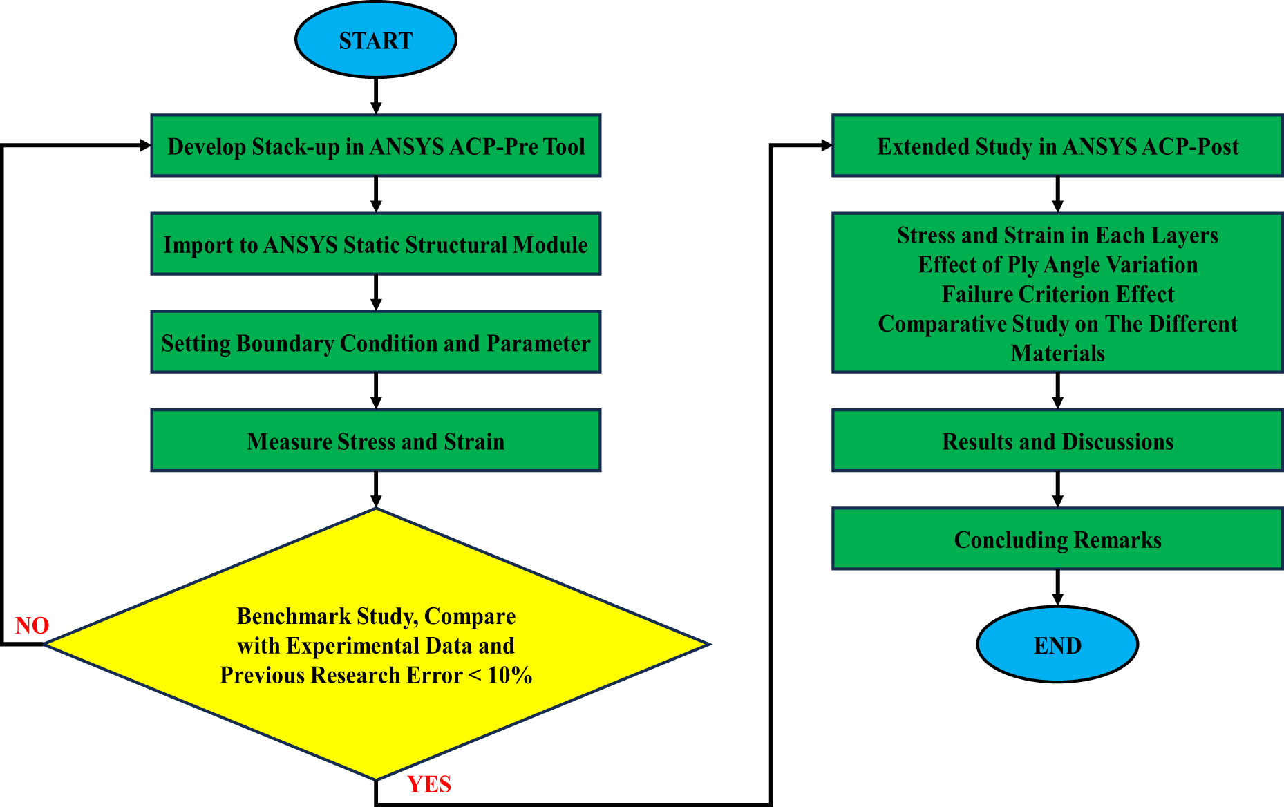
Flow diagram of the current research.
The type of fiber orientation applied was bi-directional woven CFRP. The other parameters inputted refer to previous research [20]. Then, the model is imported into the Ansys Static Structural Module. In this step, the boundary condition is set to be similar to the scenario applied during the tensile test experiment. The stress raised in the output section is the principal stress, and the strain raised is the total equivalent strain.
The simulation results are then extracted into numerical data. These data are processed using originPro software, and then the results are compared with the results of previous research. If the error that appears is less than 10%, then the method is considered valid and can be used for further research. If the error is greater, correction is needed at the previous stage. Further research will investigate the stress distribution at each layer, the influence of ply angular orientation, failure criteria, and fibers used on numerical simulation results.
3.2 Finite element configurations
The coupon test model used in this study refers to the ASTM D3039 standardization [20,43]. The dimensions of the specimen are 250 mm × 25 mm × 2.5 mm (Figure 3). The fixed support material is on one side, and the control displacement of 2 mm/min is on the other side. The maximum displacement allowed in this study is 5 mm or 0.02% of the specimen length. Uniaxial load is calculated based on reaction force on a fixed support. The damage initiation criteria used at this stage are Puck’s criterion. The material used in this study is woven fabrics of carbon (3K bi-directional plain weave, 200 GSM), which has properties as shown in Table 2.
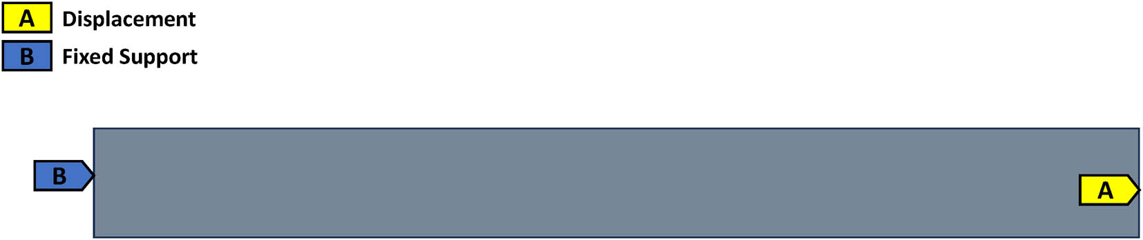
Coupon test specimens for the tensile simulation.
Material properties of the deployed CFRP in FEM [20]
| Material | CFRP |
|---|---|
| Fiber type | Bi-directional plain woven |
| Fiber orientation | 0/0/0/0/0 |
| Number of layers | 5 |
| Density | 1,434 kg/m3 |
| Modulus along the X direction, E xx | 29.2 GPa |
| Modulus along the Y direction, E yy | 29.2 GPa |
| Modulus along the Z direction, E zz | 6.67 GPa |
| Poisson’s ratio υ xy | 0.133 |
| Poisson’s ratio υ yz | 0.454 |
| Poisson’s ratio υ zx | 0.454 |
| Shear modulus in the XY plane, G xy | 1.99 GPa |
| Shear modulus in the YZ plane, G yz | 1.89 GPa |
| Shear modulus in the ZX plane, G zx | 1.89 GPa |
| Knee point (tensile test) | 125.59 MPa |
| Tangent modulus (tensile test) | 15.2 GPa |
3.3 Mesh convergence study
A mesh convergence study is a method used to determine the adequacy of the number of elements in the model used in finite-element analysis. This method is important to ensure the accuracy of numerical analysis and minimize approximation errors made by the network of elements used [44,45,46,47,48,49]. In mesh convergence studies, geometry is modeled with several different element sizes. Then, the results are analyzed and compared to ensure that the analysis results are convergent and accurate. Several meshing measures have been applied, and the simulation results are shown in Table 3. Based on the data obtained, the 7.5 mm mesh showed results similar to the results of experiments in the laboratory that had been carried out before.
Simulation results at different mesh sizes
| Mesh size (mm) | Nodes | Element | CP time (s) | Eqv stress (MPa) | Principal stress (MPa) | Total strain | Max principal elastic strain | Reaction force (N) |
|---|---|---|---|---|---|---|---|---|
| 1 | 39,156 | 31,250 | 428.08 | 307.67 | 337.21 | 0.020652 | 0.013692 | 6770.7 |
| 2 | 10,584 | 8,152 | 105.2 | 287.45 | 305.63 | 0.018154 | 0.011422 | 6777.2 |
| 3 | 4,536 | 3,320 | 41.2 | 280.17 | 291.82 | 0.017107 | 0.010204 | 6774.9 |
| 5 | 1,836 | 1,250 | 17.281 | 276.46 | 281.94 | 0.01632 | 0.0090501 | 6779.4 |
| 7.5 | 816 | 495 | 8 | 275.9 | 276.65 | 0.015964 | 0.008645 | 6785.7 |
| 10 | 624 | 375 | 6.5 | 276.73 | 276.01 | 0.015917 | 0.0086184 | 6792 |
| 15 | 324 | 170 | 3.2 | 277.69 | 274.38 | 0.01586 | 0.0086049 | 6804.7 |
| 20 | 168 | 65 | 2.6 | 279.38 | 272.72 | 0.015899 | 0.0086225 | 6816.3 |
| 25 | 132 | 50 | 2 | 280.08 | 273.37 | 0.01595 | 0.0086439 | 6833.4 |
Conducting a mesh convergence study is crucial to ensure the methods’ accuracy. The finer selection of meshes is expected to bring the simulation results closer to real conditions. However, the disadvantage is that it is more expensive and takes longer to perform computations. Therefore, the optimal element size must be carefully selected to ensure a balance between computational accuracy and efficiency. Therefore, a certain mesh size range can represent the conditions of the specimen being tested. This study recommended a mesh range of 7.5–15 mm for use. In more detail, mesh convergence studies are shown in Figure 4. The thickness of the specimen tested is 2.5 mm. Based on lab experiments, the material failed when the stress reached 277 MPa, and the strain was 0.0165.
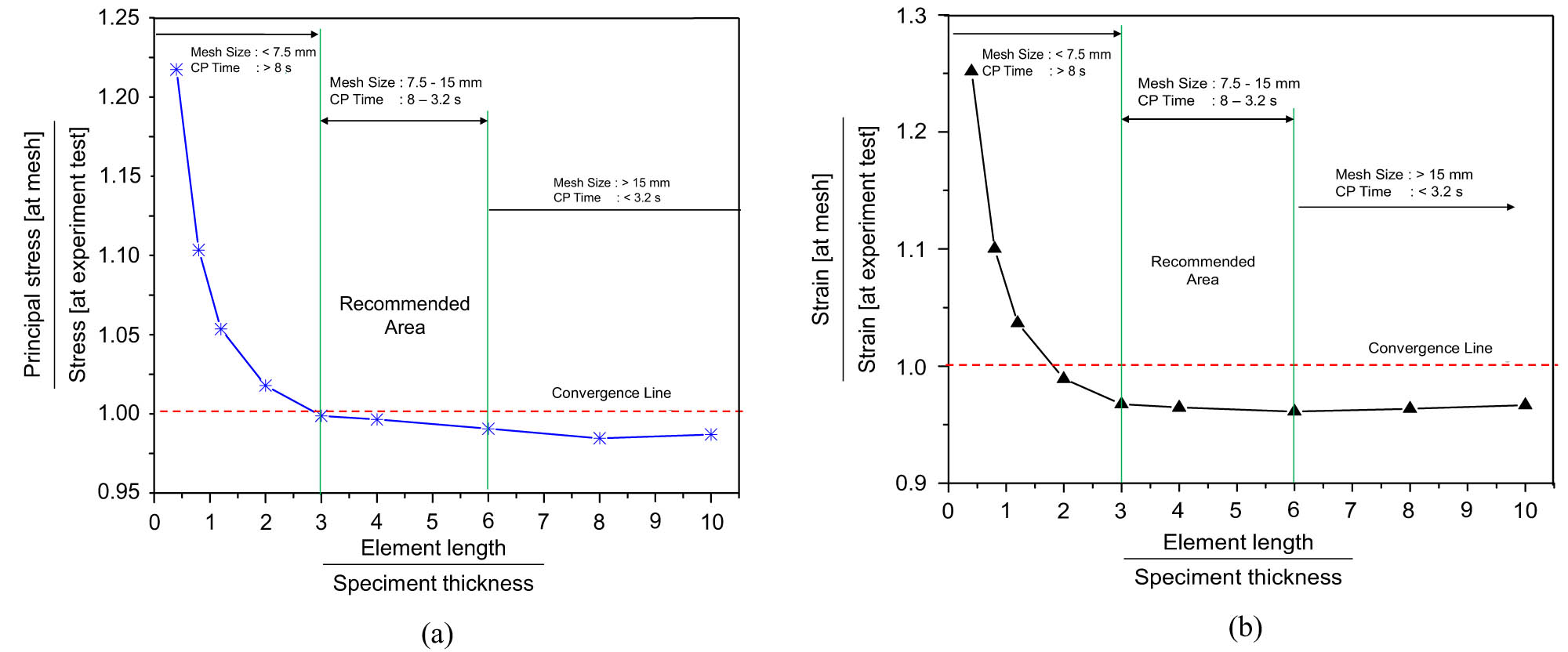
Results of the mesh convergence study: (a) stress vs element number and (b) strain result vs element number.
3.4 Benchmark study
Benchmark study is a method to validate numerical analysis results on a model by comparing it with experimental results or analytical results that are known with certainty [21,22]. This method is necessary to ensure FEM analysis meets accuracy requirements and can be used for specific purposes. The boundary conditions used in the reference and FEM replica models must be the same. In addition, the size of the elements used in the FEM model must also be selected to have the same size as the reference model used. Benchmark studies are a very important tool to ensure the accuracy and quality of FEM models in numerical analysis. Benchmark study results are used to verify and test the software and can be a standard reference for creating more complex models.
Figures 5 and 6 show the results of replicating numerical simulations from previous studies. CFRP has brittle properties, so the type of stress suitable for use is principal stress, and the strain component used is equivalent to total strain. When applying tensile force, the main stress will occur in the direction parallel or perpendicular to the direction of the fiber, depending on the orientation of the fiber and the tensile force used. Principal stress must be calculated by measuring the magnitude of the force and stretch along the direction of a particular fiber. Theoretically, when conducting tensile tests on CFRP materials, at a certain point, there will be a region with the direction of the stress vector indicated by the principal stresses, under tensile test conditions with one axis, a main direction with a higher stress value than the other direction exists. In tensile tests of CFRP materials with different variations in tensile direction, the type of principal stress formed may vary, and the stress distribution will also differ.
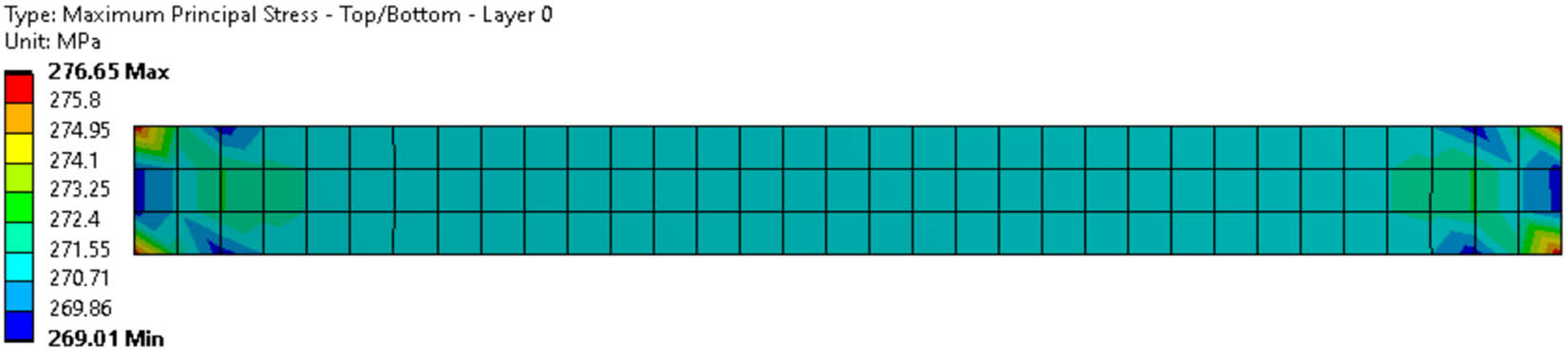
FE simulation result: maximum principal stress.
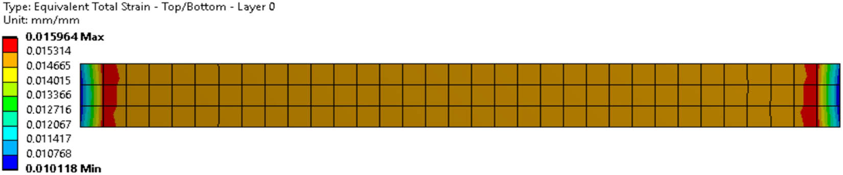
FE simulation result: equivalent total strain.
The results of the latest numerical simulations are compared with previous studies. It can be observed from Figure 7 that there has been a change in the condition that forms the knee point. The knee joint on a composite material’s stress–strain curve is a point where stress degradation and stiffness changes occur significantly [20,50,51,52,53,54]. At the knee point, the material will begin to undergo plastic deformation (permanent elongation), and the strength of the material will decrease drastically. In the stress–strain analysis of composite materials, the knee point is a breaking point where the mechanical properties change from strong to brittle and decrease significantly. Knee point analysis is important to consider the maximum strength the material can tolerate. The knee point on the stress–strain curve can determine the maximum strength limit.
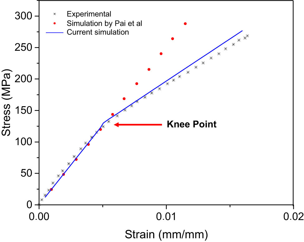
Simulation results compared to previous research, i.e., experimental and simulation works.
After passing the knee point, the modulus of elasticity is no longer valid. The tangent modulus is the parameter that can be used as a reference in the next calculation. The modulus tangent is a coefficient that measures the rate of change of the angle at which an object is bent or shaped due to force. In mathematical terms, the tangent modulus is a change in the modulus of elasticity of a material along with a change in angle. The modulus tangent is measured in units of pressure (Pa). The harder and stiffer the material, the higher the tangent value of its modulus. Therefore, tangent modulus is one of the important factors in material design because it can affect the rigidity and mechanical stability of the material. For composite materials such as CFRP, the tangent modulus is calculated by considering the orientation of the carbon fiber, the type of carbon fiber used, and the type of matrix or resin used as a carbon fiber binder. Manufacturing strong and rigid CFRP composite products relies on optimal modulus tangent values, which can be regulated through carbon fiber orientation adjustment and production processes. Inserting the tangent modulus parameter into the numerical simulation procedure makes the error smaller, as shown in Table 4.
Summarized benchmark result
| Sequences | Value | |
|---|---|---|
| Tensile modulus (GPa) | Experimental | 25.90 |
| Simulation by Pai et al. | 26.70 | |
| Current simulation | 25.77 | |
| Error (%) | 0.50 | |
| Tensile strength (MPa) | Experimental | 271.00 |
| Simulation by Pai et al. | 287.50 | |
| Current simulation | 276.65 | |
| Error (%) | 2.08 | |
| Tensile strain to failure (mm/mm) | Experimental Simulation | 0.0170 |
| Simulation by Pai et al. | 0.0120 | |
| Current simulation | 0.0160 | |
| Error (%) | 6.09 | |
4 Results and discussion
Numerical simulations had been validated using benchmarking procedures and produced relatively small errors. Furthermore, further studies had been carried out on specimens to determine the stress and strain in each layer, the influence of ply angle variations, effect failure criteria, and strength comparisons with variations in the type of fiber used.
4.1 Stress and strain distributions
The stress–strain distribution on each layer of the composite materials must be identified to ensure that the material can cope with external loads effectively. The stress and strain values in each layer can be measured using a strain gauge during the experimental test process in the laboratory and can also be predicted using FEM. Some things that must be considered are time, temperature conditions, and load points used.
The middle layer often has little stress on composite materials due to the difference in modulus of elasticity between fibers and matrix. The fibers in composite materials cause the material to be stiff and strong, while a more flexible and soft matrix can absorb energy before failure occurs. When composite materials are loaded, fibers will bear most of the stress due to their higher modulus of elasticity than matrices. The matrix on the composite material will work as a fiber binder and undergo deformation due to the stress acting on the material. Although the matrix may undergo significant stretching, its contribution to the overall strength of the composite material is smaller than that of the fiber contribution. Therefore, in the middle layer, where both types of materials are present, the stress tends to be smaller than the fiber layer or matrix around it. This phenomenon is because there is a stress transfer between the fiber and the matrix. In particular, this displacement causes the stress in the fiber to be greater and protects the matrix from failure before the stress reaches the strength limit of the matrix. However, this is only a general principle, and stress in the middle layer can also depend on the orientation of the fibers, the thickness of the layer, and the type of material used in the composite material.
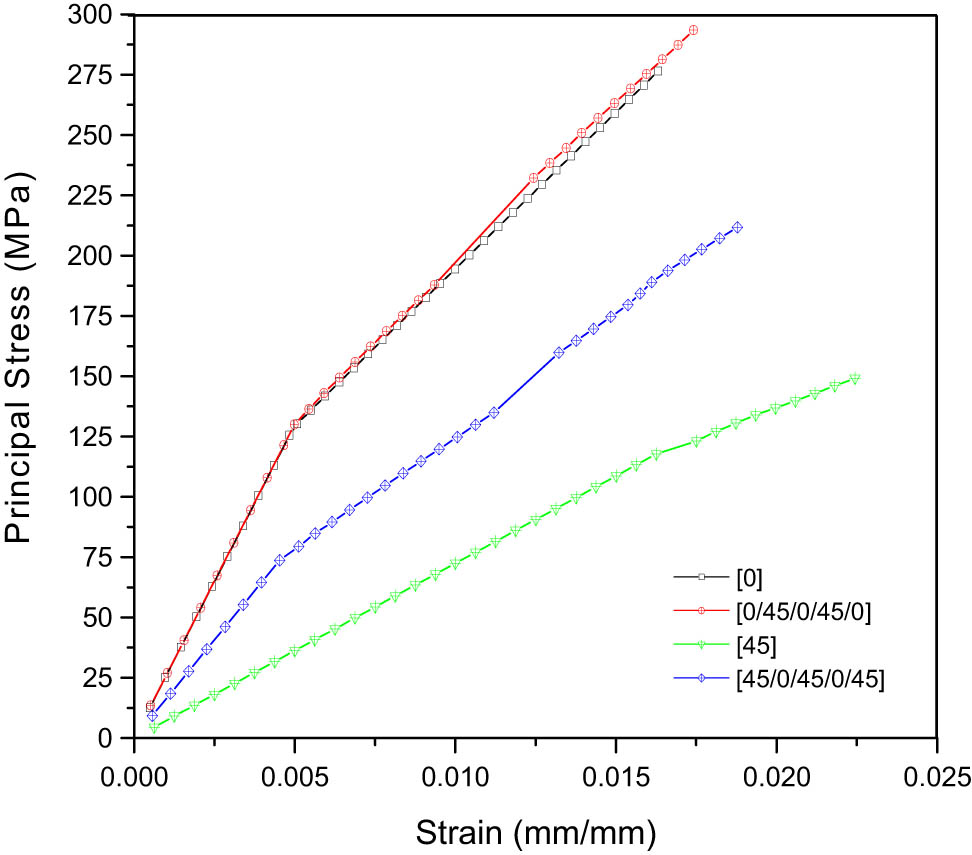
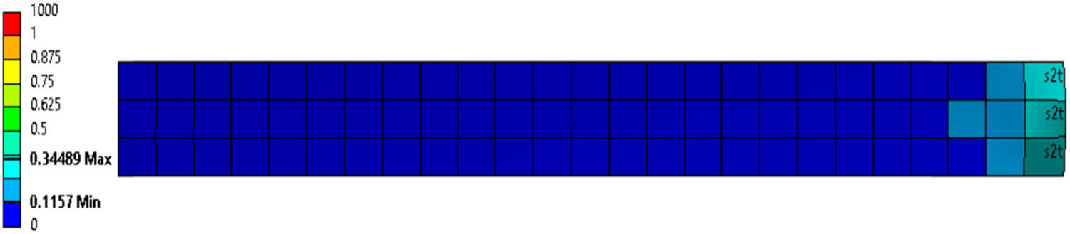
Different ply angle variation conditions are needed with the benchmarking procedure, namely [0/45/0/45/0], to identify the influence of fiber orientation on the stress distribution. The stress that occurs in layers with a fiber orientation of 45° is very small, and the layer has a modulus of elasticity higher than 0° (Figures 8–10). Oriented layers 45° can stretch and distribute forces better before undergoing plastic deformation.
![Figure 8
FE simulation result: principal stress on each layer [0/45/0/45/0].](/document/doi/10.1515/cls-2024-0002/asset/graphic/j_cls-2024-0002_fig_008.jpg)
FE simulation result: principal stress on each layer [0/45/0/45/0].
![Figure 9
FE simulation result: strain on each layer [0/45/0/45/0].](/document/doi/10.1515/cls-2024-0002/asset/graphic/j_cls-2024-0002_fig_009.jpg)
FE simulation result: strain on each layer [0/45/0/45/0].
![Figure 10
Behaviors of the stress and strain on each layer [0/45/0/45/0].](/document/doi/10.1515/cls-2024-0002/asset/graphic/j_cls-2024-0002_fig_010.jpg)
Behaviors of the stress and strain on each layer [0/45/0/45/0].
4.2 Effect of ply angle variation
The ply angle variant is one of the important factors in the design of composite materials, including CFRP. Ply angle variations (Figure 11) can affect the elasticity and pressure distribution modulus. An even distribution of pressure can increase the strength within the material against deformation and stress. At certain ply angles, the material can exhibit a more effective form of damage, protecting the material and reducing susceptibility to cracking and fracture in the future. In general, using different ply angle variations with a certain strain direction can increase the strength of the material in the required direction. Ply angle also affects the material’s stiffness, where when the ply angle is smaller, the material’s stiffness becomes better.
Summarized effect of ply angle variation.
4.3 Failure criterion
CFRP material is one of the thin-walled structure-grade materials that are of high quality and often used in the aviation and space industries. The selection of failure criteria that are most suitable for thin-walled structure applications in composite materials must consider the specific properties of the composite material, the operational environment, and the load conditions to be faced. The selection of failure criteria should be based on an in-depth analysis of the mechanical properties of the composite material, including the type of fiber and matrix used, the direction of the fiber, and the expected environment and operating conditions. Combining analysis results with materials testing and experimental validation is important to ensure that selected criteria provide accurate failure prediction in thin-walled structure applications. The value of the principal stress and strain in the specimen is considered linear until it reaches one of the limits of the failure criteria. The selection of failure criteria applied will show different safety indices. The distribution of failures on each node and element will show results that vary as per the limit value. Failure criteria can further be used to predict failure mode in specimens. This study tried to compare the safety index in the specimen, especially in the first layer. Each scenario has the same boundary conditions and input parameters. Only the failure criteria are varied.
The failure index method is a more general approach that combines multiple failure criteria to calculate a total failure index. It helps identify critical points in the structure that may experience failure. Puck failure criteria have been used in benchmarking procedures until the material fails. It can be observed in Table 5 and compared with Figure 1; it is proven that the maximum stress criterion and the Hashin criterion have the same limit value, so the Inverse Reserve Factor of the Safety index is also the same. Tsai–Wu and Hoffman also have a similar distribution for this case. Tsai–Hill is a conservative criterion and assumes that the material will fail early. Tsai–Hill will define failure faster when compared to other criteria.
FE simulation result: Inverse reserve factor of safety
| Failure criteria | Result |
|---|---|
| Maximum stress |
 |
| Tsai–Hill |
 |
| Tsai–Wu |
 |
| Hashin |
 |
| Hoffman |
 |
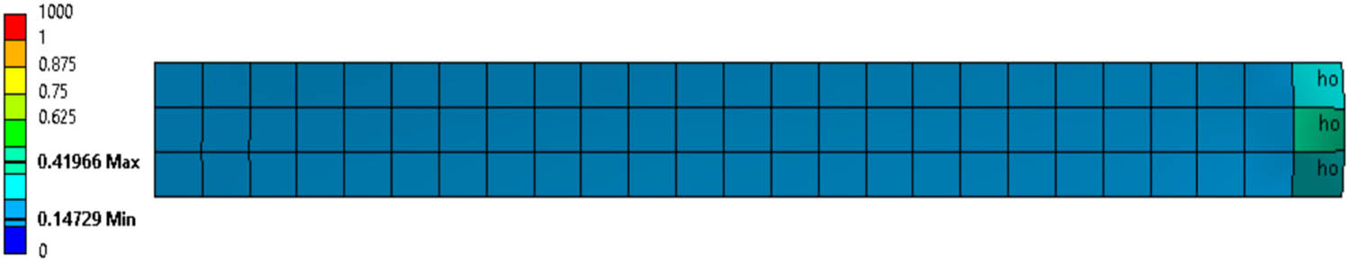
4.4 Comparative results on reinforced types
Carbon fiber, S-glass, and E-glass are fibers often used in composite materials to increase the strength and rigidity of materials. Carbon fiber has very high strength and great rigidity. This material has a low specific gravity, about 1.78 g/cm3. Its superior properties include corrosion resistance, high-temperature resistance, rigidity, resistance to deformation, lightweightness, and durability. However, this composite type is expensive, cannot be glued together easily, and tends to be brittle. Composites with S-glass reinforcement have a higher specific gravity than carbon fiber but have stronger properties than E-glass. S-glass-reinforced composites are highly resistant to pressure and deformation but less resistant to tensile forces. This material is more economical than carbon fiber. E-glass-reinforced composites have the worst strength and specific gravity. Nevertheless, this material is very cheap and easy to glue. The downside is that it is not corrosion-resistant and less resistant to high temperatures.
Figure 12 shows simulation results for the tensile strength of three composites. It can be seen that carbon-fiber-reinforced composites have the most excellent characteristics. E-glass and S-glass reinforced composites have almost similar characteristics. All three types of boosters have their characters and applications. The comparison results show one of the compelling reasons why carbon fiber is preferred for thin-walled structure applications.
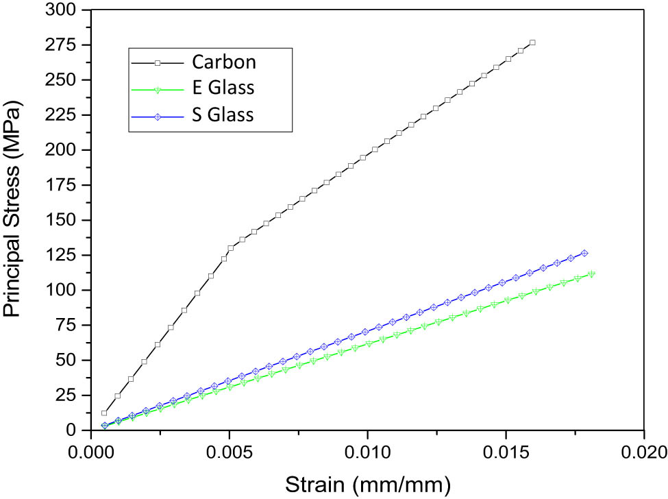
Comparative study considering different fiber types.
5 Concluding remarks
A good understanding of stress and strain distribution in each layer in CFRP can help improve mechanical performance and material performance in industrial applications and minimize the risk of unwanted material failure. The proper orientation of the CFRP woven fiber can affect the material’s performance and strength. Planning and evaluating ply angles will help optimize and improve the mechanical properties of composite materials and maximize the material’s potential in various applications, one of which is for thin-walled structure. Properly selecting ply angles can improve strength, stiffness, fatigue resistance, and behavior to impact loads and other extreme conditions.
In selecting failure criteria for composite materials, selecting criteria that fit specific application conditions is important. Puck criteria can be used for simple applications, which require only the analysis of the main stresses in the material. Meanwhile, Tsai–Hill and Tsai–Wu can provide more accurate prediction results and are better suited for loading conditions and more complex material types.
The comparison of fiber types shows that each type has advantages and disadvantages, depending on its application. S-glass has good strength and rigidity, and the price is more economical than carbon fiber. E-glass is cheaper and easier to glue but has lower strength and rigidity. Carbon fiber has excellent strength, rigidity, and rigidity and other superior properties, making it suitable for high-performance applications. The disadvantage of CFRP is that it is expensive and requires sophisticated technology. Therefore, fiber selection depends on the needs of the application and the available budget.
Further research is needed to consider the use of other approaches in modeling CFRP materials, such as the generalized differential quadrature method and shell theories of varying orders. High orders are typically modeled using the equivalent single layer theory technique. Furthermore, more sophisticated changes of material properties such as anisotropy, orthotropy, and transverse-isotropy should be considered.
-
Funding information: This work was supported by Universitas Sebelas Maret under research scheme Penelitian Unggulan Terapan (PUT-UNS) Year 2024 with the assigned contract number 194.2/UN27.22/PT.01.03/2024. The external support from Research Organization for Aeronautics and Space of National Research and Innovation Agency (BRIN) no. 15/III.1/HK/2023 (PP.4.01) is highly acknowledged.
-
Author contributions: All authors have accepted responsibility for the entire content of this manuscript and approved its submission.
-
Conflict of interest: The authors declare no conflicts of interest.
-
Data availability statement: The authors declare that the data supporting the findings of this study are available within the article.
References
[1] Huda Z, Edi P. Materials selection in design of structures and engines of supersonic aircrafts: A review. Mat Des. 2013;46:552–60. 10.1016/j.matdes.2012.10.001.Search in Google Scholar
[2] Wanhill R, Molent L, Barter S. Milestone aircraft case histories and continuing developments - in Comprehensive Structural Integrity. Amsterdam, Netherlands: Elsevier Science; 2023.Search in Google Scholar
[3] Goncharenko AV. Aeronautical and aerospace material and structural damages to failures: Theoretical concepts. Int J Aero Eng. 2018;2018:4126085. 10.1155/2018/4126085.Search in Google Scholar
[4] Bishara M, Horst P, Madhusoodanan H, Brod M, Daum B, Rolfes R. A structural design concept for a multi-shell blended wing body with laminar flow control. Energies. 2018;11(2):383. 10.3390/en11020383.Search in Google Scholar
[5] Soutis C. Introduction: Engineering requirements for aerospace composite materials - in Polymer Composites in the Aerospace Industry. Sawston, United Kingdom: Woodhead Publishing; 2014.Search in Google Scholar
[6] Abdurohman K, Marta A. Experimental study of tensile properties of unidirectional carbon fiber reinforced polyester composites result of vacuum infusion manufacturing as LSU structural material. J Tek Dirgant. 2016;14(1):61–72. 10.30536/j.jtd.2016.v14.a2568 (in Indonesian).Search in Google Scholar
[7] Spearrin RM, Bendana FA. Design-build-launch : a hybrid project-based laboratory course for aerospace engineering education. Act Astronautic. 2019;157(October):29–39. 10.1016/j.actaastro.2018.11.002.Search in Google Scholar
[8] Fanani EWA, Surojo E, Prabowo AR, Ariawan D, Akbar HI. Recent development in aluminum matrix composite forging: Effect on the mechanical and physical properties. Proc Struct Integ. 2021;33:3–10. 10.1016/j.prostr.2021.10.002.Search in Google Scholar
[9] Duan Y, Cui Z, Xie X, Tie Y, Zou T, Wang T. Mechanical characteristics of composite honeycomb sandwich structures under oblique impact. Theor Appl Mech Lett. 2022;12(5):100379. 10.1016/j.taml.2022.100379.Search in Google Scholar
[10] Du Y, Ma Y, Sun W, Wang Z. Effect of hygrothermal aging on moisture diffusion and tensile behavior of CFRP composite laminates. Chin J Aeronautic. 2023;36(3):382–92. 10.1016/j.cja.2022.11.022.Search in Google Scholar
[11] Muflikhun MA, Higuchi R, Yokozeki T, Aoki T. Failure mode analysis of CFRP-SPCC hybrid thin laminates under axial loading for structural applications: Experimental research on strain performance. Compos Part B Eng. 2019;172(2):262–70. 10.1016/j.compositesb.2019.05.049.Search in Google Scholar
[12] Rogani A, Navarro P, Marguet S, Ferrero JF, Lanouette C. Tensile post-impact behaviour of thin carbon/epoxy and glass/epoxy hybrid woven laminates – Part II: Numerical study. Compos Struct. 2019;230(September):111455. 10.1016/j.compstruct.2019.111455.Search in Google Scholar
[13] Jiang D, Ma R, Wu S, Fei Q. Numerical-experimental method for elastic parameters identification of a composite panel. Theor Appl Mech Lett. 2014;4(6):061001. 10.1063/2.1406101.Search in Google Scholar
[14] Kumar RR, Reddy KLHC, Velu N, Balaji SG, Shankar MS. Finite element analysis of carbon woven fiber with epoxy sandwich composite for structural analysis. Mat Today Proc. 2022;68:2032–7. 10.1016/j.matpr.2022.08.355.Search in Google Scholar
[15] Suryanto S, Prabowo AR, Muttaqie T, Istanto I, Adiputra R, Muhayat N, et al. Evaluation of high-tensile steel using nonlinear analysis: Experiment-FE materials benchmarking of LNG carrier structures under low-temperature conditions. Energy Rep. 2023;9(Supplement 9):149–61. 10.1016/j.egyr.2023.05.252.Search in Google Scholar
[16] Khawaja HA, Bertelsen TA, Andreassen R, Moatamedi M. Study of CRFP shell structures under dynamic loading in shock tube setup. J Struct. 2014;2014:487809. 10.1155/2014/487809.Search in Google Scholar
[17] Shaikh AA, Pradhan AA, Kotasthane AM, Patil S, Karuppanan S. Comparative analysis of Basalt/E-Glass/S2-Fibreglass-Carbon fiber reinforced epoxy laminates using finite element method. Mat Today Proc. 2022;63:630–8. 10.1016/j.matpr.2022.04.385.Search in Google Scholar
[18] Reinoso J, Catalanotti G, Blázquez A, Areias P, Camanho PP, París F. A consistent anisotropic damage model for laminated fiber-reinforced composites using the 3D-version of the Puck failure criterion. Int J Sol Struct. 2017;126–127:37–53. 10.1016/j.ijsolstr.2017.07.023.Search in Google Scholar
[19] Hohe J, Schober M, Weiss KP, Appel S. Verification of Puck’s criterion for CFRP laminates under multiaxial loads at ambient and cryogenic temperatures. Compos Sci Technol. 2022;228:109631. 10.1016/j.compscitech.2022.109631.Search in Google Scholar
[20] Pai A, Suri R, Bhave AK, Verma P, Padmaraj NH. Puck ‘ s criterion for the tensile response of composite laminates : A numerical approach. Adv Eng Softw. 2023;175:103364. 10.1016/j.advengsoft.2022.103364.Search in Google Scholar
[21] Fajri A, Prabowo AR, Muhayat N. Assessment of ship structure under fatigue loading: FE benchmarking and extended performance analysis. Curve Layer Struct. 2022;9(1):163–86. 10.1515/cls-2022-0014.Search in Google Scholar
[22] Fajri A, Prabowo AR, Surojo E, Imaduddin F, Sohn JM, Adiputra R. Validation and verification of fatigue assessment using FE analysis: A study case on the notched cantilever beam. Proc Struct Integ. 2021;33:11–8. 10.1016/j.prostr.2021.10.003.Search in Google Scholar
[23] Davila C, Jaunky N, Goswami S. Failure criteria for FRP laminates in plane stress. The 44th AIAA/ASME/ASCE/AHS/ASC Structures, Structural Dynamics, and Materials Conference, Norfolk, United States; 2023. 10.2514/6.2003-1991.Search in Google Scholar
[24] Frossard G, Cugnoni J, Gmür T, Botsis J. Mode I interlaminar fracture of carbon epoxy laminates: Effects of ply thickness. Compos Part A: Appl Sci Manuf. 2016;91:1–8. 10.1016/j.compositesa.2016.09.009.Search in Google Scholar
[25] Oddy C, Ekermann T, Ekh M, Fagerström M, Hallström S, Stig F. Predicting damage initiation in 3D fibre-reinforced composites – The case for strain-based criteria. Compos Struct. 2019;230:111336. 10.1016/j.compstruct.2019.111336.Search in Google Scholar
[26] Razavi SMJ, Neisiany RE, Khorasani SN, Ramakrishna S, Berto F. Effect of neat and reinforced polyacrylonitrile nanofibers incorporation on interlaminar fracture toughness of carbon/epoxy composite. Theol Appl Mech Lett. 2018;8(2):126–31. 10.1016/j.taml.2018.02.008.Search in Google Scholar
[27] Ariawan D, Surojo E, Triyono J, Purbayanto IF, Pamungkas AF, Prabowo AR. Micromechanical analysis on tensile properties prediction of discontinuous randomized zalacca fibre/high-density polyethylene composites under critical fibre length. Theor Appl Mech Lett. 2020;10(1):57–65. 10.1016/j.taml.2020.01.009.Search in Google Scholar
[28] Müzel SD, Bonhin EP, Guimarães NM, Guidi ES. Application of the finite element method in the analysis of composite materials: A review. Polym. 2020;12(4):818. 10.3390/polym12040818.Search in Google Scholar PubMed PubMed Central
[29] Tsai SW, Wu EM. A general theory of strength for anisotropic materials. J Compos Mat. 1971;5(1):58–80. 10.1177/002199837100500106.Search in Google Scholar
[30] Nali P, Carrera E. A numerical assessment on two-dimensional failure criteria for composite layered structures. Compos Part B Eng. 2012;43(2):280–9. 10.1016/j.compositesb.2011.06.018.Search in Google Scholar
[31] Yang C, Jiao G, Guo H. Failure criteria for C/SiC composites under plane stress state. Theor Appl Mech Lett. 2014;4(2):021007. 10.1063/2.1402107.Search in Google Scholar
[32] Reddy JN. A generalization of two-dimensional theories of laminated composite plates. Commun Appl Numer Method. 1987;3(3):173–80. 10.1002/cnm.1630030303.Search in Google Scholar
[33] Reddy JN. Mechanics of laminated composite plates and shells: Theory and analysis. Boca Raton, United States: CRC Press; 2003.10.1201/b12409Search in Google Scholar
[34] Puck A, Schürmann H. Failure analysis of FRP laminates by means of physically based phenomenological models. Compos Sci Technol. 2002;62(12–13):1633–62. 10.1016/S0266-3538(01)00208-1.Search in Google Scholar
[35] Hill R. Theory of mechanical properties of fibre-strengthened materials – III. self-consistent model. J Mech Phys Sol. 1965;13(4):189–98. 10.1016/0022-5096(65)90008-6.Search in Google Scholar
[36] Tsai SW. Strength theories of filamentary structures. In: Fundamental aspects of fiber reinforced plastic composites. New York: Wiley Interscience; 1968.Search in Google Scholar
[37] Hashin Z, Rotem A. A fatigue failure criterion for fiber reinforced materials. J Compos Mat. 1973;7(4):448–64. 10.1177/002199837300700404.Search in Google Scholar
[38] Hashin Z. Failure criteria for unidirectional fiber composites. J Appl Mech. 1980;47(2):329–34. 10.1115/1.3153664.Search in Google Scholar
[39] Hoffman O. The brittle strength of orthotropic materials. J Compos Mat. 1967;1(2):200–6. 10.1177/002199836700100210.Search in Google Scholar
[40] Tornabene F, Fantuzzi N, Bacciocchi M, Dimitri R. Free vibrations of composite oval and elliptic cylinders by the generalized differential quadrature method. Thin Wall Struct. 2015;97:114–29. 10.1016/j.tws.2015.08.023.Search in Google Scholar
[41] Noroozi AR, Malekzadeh P, Dimitri R, Tornabene F. Meshfree radial point interpolation method for the vibration and buckling analysis of FG-GPLRC perforated plates under an in-plane loading. Eng Struct. 2020;221:111000. 10.1016/j.engstruct.2020.111000.Search in Google Scholar
[42] Tornabene F, Viscoti M, Dimitri R. Higher order theories for the modal analysis of anisotropic doubly-curved shells with a three-dimensional variation of the material properties. Eng Anal Bound Elem. 2024;158:486–519. 10.1016/j.enganabound.2023.11.008.Search in Google Scholar
[43] Venkatesan K, Ramanathan K, Vijayanandh R, Selvaraj S, Kumar GR, Kumar MS. Comparative structural analysis of advanced multi-layer composite materials. Mat Today Proc. 2019;27:2673–87. 10.1016/j.matpr.2019.11.247.Search in Google Scholar
[44] Prabowo AR, Ridwan R, Muhayat N, Putranto T, Sohn JM. Tensile analysis and assessment of carbon and alloy steels using fe approach as an idealization of material fractures under collision and grounding. Curve Layer Struct. 2020;7(1):188–98. 10.1515/cls-2020-0016.Search in Google Scholar
[45] Mettanadi AH, Prabowo AR, Kusharjanta B, Muttaqie T, Laksono FB, Nubli H. Crashworthiness performance of the designed concave hexagonal structures as filler element in cylindrical shells in multiple load cases. Frat Integ Strut. 2023;17(65):135–59. 10.3221/IGF-ESIS.65.10.Search in Google Scholar
[46] Prabowo AR, Ridwan R, Tuswan T, Imaduddin F. Forecasting the effects of failure criteria in assessing ship structural damage modes. Civ Eng J. 2022;8(10):2053–68. 10.28991/CEJ-2022-08-10-03.Search in Google Scholar
[47] Avi E, Laakso A, Romanoff J, Remes H, Avi IL. Coarse mesh finite element model for cruise ship global and local vibration analysis. Mar Struct. 2021;79:103053. 10.1016/j.marstruc.2021.103053.Search in Google Scholar
[48] Nurcholis A, Prabowo AR, Yaningsih I, Muttaqie T, Nubli H, Huda N, Fajri A. Idealized fire-structures interaction on ship and offshore building members: A benchmark study using explicit-dynamic FE approach. Proc Struct Integ. 2023;48:33–40. 10.1016/j.prostr.2023.07.107.Search in Google Scholar
[49] Prabowo AR, Ridwan R, Braun M, Song S, Ehlers S, Firdaus N, Adiputra R. Comparative study of shell element formulations as NLFE parameters to forecast structural crashworthiness. Curve Layer Struct. 2023;10(1):20220217. 10.1515/cls-2022-0217.Search in Google Scholar
[50] Puck A, Schürmann H. Failure analysis of FRP laminates by means of physically based phenomenological models. In Failure criteria in fibre-reinforced-polymer composites. Amsterdam, Netherlands: Elsevier Science; 2004.10.1016/B978-008044475-8/50028-7Search in Google Scholar
[51] Khashaba UA. Impact of standard and unexpected bolt-hole-washer tolerances on the performance of pinned and torqued joints in CFRP composites. Alex Eng J. 2023;81:290–303. 10.1016/j.aej.2023.09.037.Search in Google Scholar
[52] Koord J, Völkerink O, Petersen E, Hühne C. Effect of low temperature on mode I and mode II interlaminar fracture toughness of CFRP-steel hybrid laminates. Compos Part B Eng. 2023;262:110773. 10.1016/j.compositesb.2023.110773.Search in Google Scholar
[53] Kapidžić Z, Granados DLA, Arias JAM, Aguilera MJQ, Rodríguez JBC, Callejas JCG. Bolt fatigue in CFRP joints. Int J Fat. 2022;164:107138. 10.1016/j.ijfatigue.2022.107138.Search in Google Scholar
[54] Can A, Meram A. Dynamic behavior of screwed joints for CFRP composite laminate structures under impact loading. J Manuf Process. 2022;75:232–42. 10.1016/j.jmapro.2022.01.016.Search in Google Scholar
© 2024 the author(s), published by De Gruyter
This work is licensed under the Creative Commons Attribution 4.0 International License.
Articles in the same Issue
- Research Articles
- Flutter investigation and deep learning prediction of FG composite wing reinforced with carbon nanotube
- Experimental and numerical investigation of nanomaterial-based structural composite
- Optimisation of material composition in functionally graded plates for thermal stress relaxation using statistical design support system
- Tensile assessment of woven CFRP using finite element method: A benchmarking and preliminary study for thin-walled structure application
- Reliability and sensitivity assessment of laminated composite plates with high-dimensional uncertainty variables using active learning-based ensemble metamodels
- Performances of the sandwich panel structures under fire accident due to hydrogen leaks: Consideration of structural design and environment factor using FE analysis
- Recycling harmful plastic waste to produce a fiber equivalent to carbon fiber reinforced polymer for reinforcement and rehabilitation of structural members
- Effect of seed husk waste powder on the PLA medical thread properties fabricated via 3D printer
- Finite element analysis of the thermal and thermo-mechanical coupling problems in the dry friction clutches using functionally graded material
- Strength assessment of fiberglass layer configurations in FRP ship materials from yard practices using a statistical approach
- An enhanced analytical and numerical thermal model of frictional clutch system using functionally graded materials
- Using collocation with radial basis functions in a pseudospectral framework to the analysis of laminated plates by the Reissner’s mixed variational theorem
- A new finite element formulation for the lateral torsional buckling analyses of orthotropic FRP-externally bonded steel beams
- Effect of random variation in input parameter on cracked orthotropic plate using extended isogeometric analysis (XIGA) under thermomechanical loading
- Assessment of a new higher-order shear and normal deformation theory for the static response of functionally graded shallow shells
- Nonlinear poro thermal vibration and parametric excitation in a magneto-elastic embedded nanobeam using homotopy perturbation technique
- Finite-element investigations on the influence of material selection and geometrical parameters on dental implant performance
- Study on resistance performance of hexagonal hull form with variation of angle of attack, deadrise, and stern for flat-sided catamaran vessel
- Evaluation of double-bottom structure performance under fire accident using nonlinear finite element approach
- Behavior of TE and TM propagation modes in nanomaterial graphene using asymmetric slab waveguide
- FEM for improvement of damage prediction of airfield flexible pavements on soft and stiff subgrade under various heavy load configurations of landing gear of new generation aircraft
- Review Article
- Deterioration and imperfection of the ship structural components and its effects on the structural integrity: A review
- Erratum
- Erratum to “Performances of the sandwich panel structures under fire accident due to hydrogen leaks: Consideration of structural design and environment factor using FE analysis”
- Special Issue: The 2nd Thematic Symposium - Integrity of Mechanical Structure and Material - Part II
- Structural assessment of 40 ft mini LNG ISO tank: Effect of structural frame design on the strength performance
- Experimental and numerical investigations of multi-layered ship engine room bulkhead insulation thermal performance under fire conditions
- Investigating the influence of plate geometry and detonation variations on structural responses under explosion loading: A nonlinear finite-element analysis with sensitivity analysis