Finite element analysis of the thermal and thermo-mechanical coupling problems in the dry friction clutches using functionally graded material
-
Nasr A. Jabbar
 and
M. N. Mohammed
and
M. N. Mohammed

Abstract
The friction clutch is an important machine part in the torque transmission system, where it is responsible for gently transmitting the power from the engine to the gearbox and damping the tensional vibration. At the beginning of the engagement between the clutch’s elements, a large amount of heat is released due to frictional sliding between the elements of the clutch system, generating very high temperatures. In this work, the two- and three-dimensional finite element models were developed from scratch to explore the clutch disk’s temperature and contact pressure behaviors using an alternative frictional material such as functionally graded material (FGM). The two assumptions for the thermal loads were considered: uniform wear and uniform pressure assumptions. The thermal–structural problem for the new frictional material was solved numerically and then presented as the temperature distributions and the contact pressure at any instant of sliding time. Also, a comparison was made between the clutch system behaviors when using FGM with different frictional materials. The results showed that the FGM has superior results to the other available frictional materials.
Nomenclature
- K
-
thermal conductivity (W m−1 K−1)
- n p
-
number of friction disks
- P
-
pressure (N m−2)
- q
-
frictional heat generated (W m−2)
- r
-
radius of clutch (m)
- r i
-
inner radius of clutch (m)
- r o
-
outer radius of clutch (m)
- t
-
time (s)
- T
-
torque (N m)
- t
-
slip time (s)
Greek symbols
-
-
angular velocity at slipping period (rad s−1)
- ε i,j
-
components of thermal strain
- v
-
Poisson’s ratio
-
-
stress tensor (N m−2)
-
-
thermal diffusivity (m2 s−1)
- µ
-
friction coefficient
1 Introduction
The clutch’s primary function is to transmit torque from the engine to the driven shaft, as well as engage and disengage the transmission system. When the friction clutch begins to engage, slipping occurs between the contact surfaces of the pressure plate, friction plate, and flywheel. Slipping between the elements of the clutch generates heat energy on the frictional surfaces [1]. Figure 1 shows the main elements of the dry friction clutch system, which are the friction clutch disk, flywheel, and pressure plate.
![Figure 1
Main elements of the dry friction clutch system [2].](/document/doi/10.1515/cls-2024-0001/asset/graphic/j_cls-2024-0001_fig_001.jpg)
Main elements of the dry friction clutch system [2].
A major reason for dry clutch failure is the excessive heat generation via sliding friction during the initial engagement, which increases the wear rate. Consequently, it changes the surface characteristics and makes the contact pressure focus on a certain zone from the nominal contact area. This change in the contact pressure will increase the heat generated several times more than in the case of normal contact pressure. So, the temperatures will increase extremely in this zone and exceed the maximum allowable temperature for the used materials. Therefore, the failure will occur on contact surfaces before the designed lifetime.
Generated heat also changes the friction characteristics of the frictional-facing material through thermal degradation, wear, and distortion of the friction disk by converting generated heat into thermal stresses. Changes in the clutch facing’s friction characteristics can lead to a greater propensity to judder [3,4]. Distortion of the friction disk causes uneven contact with the pressure plate and the flywheel, resulting in localized contact pressure, hot-spotting phenomena, and thermoelastic instability [5,6]. Kinetic energy is converted into thermal energy, generating heat during the clutch engagement process. The main parameters affecting this process are the interfacial sliding speed, the applied contact pressure (clamp load), the coefficient of friction of the contacting surfaces, and the thermal properties of the materials in contact. The changes in friction characteristics with pressure and interfacial slip speed (e.g., a negative gradient of the coefficient of friction with slip speed) can lead to coupling instabilities manifested in the form of judder vibrations in the vehicle [7,8]. Yang et al. [9] investigated the formulation of variational principles characterizing the solutions of the coupled thermo-mechanical problem for general dissipative solids. At the same time, Bagri and Eslami [10] presented the finite element model (FEM) of generalized coupled thermoelasticity equations for a hollow disk subjected to a thermal shock. The Laplace transform method was used to transform the thermoelasticity equations. A few studies used the FEM to investigate the thermoelastic coupling behavior of clutch systems [11,12,13,14,15,16]. Chen et al. [17] proposed a new approach to modeling the temperature based on computational fluid dynamics simulation and decoupling technology. They used the flow-thermal bi-directional coupling method to determine the convective boundary conditions between the clutch assembly and the ambient air, improving the model’s accuracy. Padmanabhan et al. [18] introduced an investigation of structural and thermal analysis of clutch facings with different friction materials. Clutch facings composed of base material have been modeled and analyzed in Solid Works and ANSYS Workbench. Liu et al. [19] modeled a numerical solution to obtain the surface temperature at different radii based on the FEM. And then, the data were compared with the experimental data. The result appears that the proposed model for estimating the surface temperature is more accurate than the conventional prediction method. Haojie and Zhaoquan [20] carried coupling field transient analysis of the clutch under continuous sliding wear conditions, and the clutch temperature change and heat generated by friction were obtained by simulation calculation under the use of simulated clutch holding for 1 s. Based on the results of the simulation, the factors that may affect the friction heat generation of the clutch are analyzed. Xie et al. [21] analyzed the thermal load characteristics of the dry dual clutch under the condition of multiple starting on the ramp by software ABAQUS. The study obtains the distributions of the transient temperature field of the clutch friction pair under the conditions of multiple starting.
This article introduced two FEMs. The first model was developed to study the thermal behavior of the clutch system using a functionally graded material (FGM) disk under uniform pressure and wear assumptions. The second model was developed to find the solution to the thermo-elastic coupling problem using an FGM disk. The comparisons were made between the thermal behavior and performance of the clutch system using FGM material and the available (commercial) frictional materials (VH-03 and HDS57).
2 Finite element formulation
Transient conditions involved a time-dependent function of the heat transfer analysis. During the transient condition, the temperature change in a unit volume of material is resisted by thermal mass that depends on the mass density ρ of the material and its specific heat c. The finite element formulation can be expressed as [22]
where [C] is the specific heat matrix, {
2.1 Thermal problem
Elevated local temperatures caused energy buildup at contact, leading to new wear particles and subsurface fracture propagation. Studying the slipping and heat dissipation periods is crucial to comparing the thermal behavior using different friction materials. During the sliding period, the formula calculates the heat produced assuming the uniform pressure between the contact surfaces is
However, under uniform wear conditions, the frictional heat generation during the slipping duration is equal to [24]
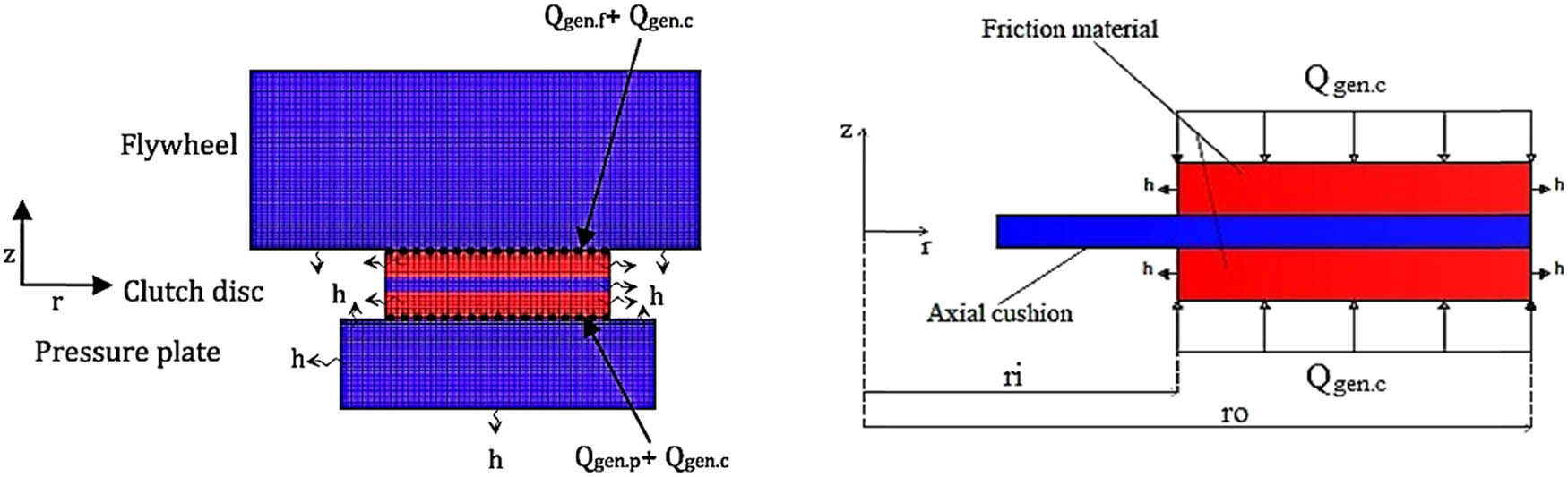
The models that represent the distribution of the frictional heat generation between the contact surfaces of the clutch’s elements are shown in Figure 2.
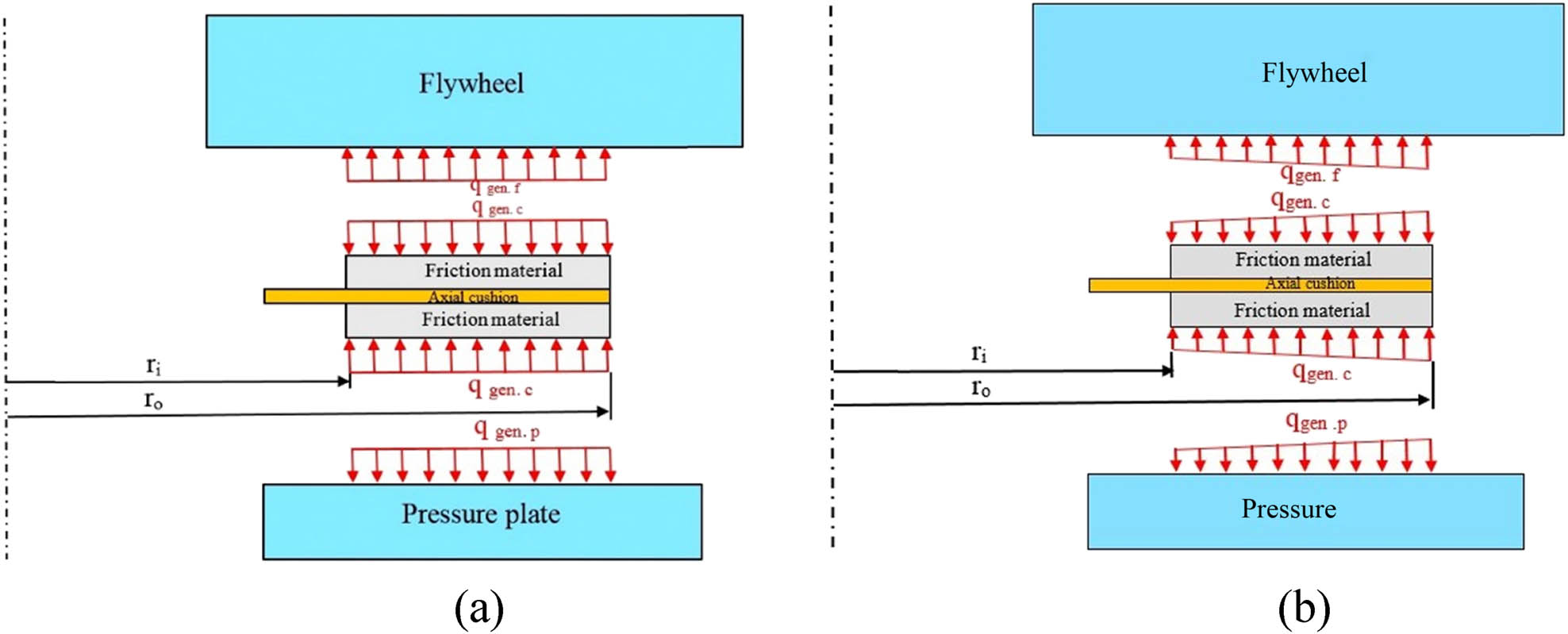
Distribution of the frictional heat generation between the contact surfaces of the clutch’s elements: (a) uniform wear theory and (b) uniform pressure theory.
A three-dimensional FEM (3D FEM) for the friction clutch system is very necessary to understand the complex thermal behavior displayed by clutch systems during the early engagement stages. The creation of such a FEM needs high skills and time. This model will simulate how the kinetic energy transforms into heat through contact sliding between the elements of the clutch system (flywheel, pressure plate, and clutch disk). It used two types of element types: hexahedral (hexa) and tetrahedral (tetra) to build the FEM of the clutch system.
This model overcame some challenges that faced the complexity of the geometry validity process, the parametric study, etc. Two types of frictional materials were analyzed using this developed FE model: FGM and commercial frictional materials (VH-03 and HDS57). The element-type “hexahedral” is chosen because it is well known for its efficiency in representing complex geometries with mathematical stability intricacies exhibited by clutch systems. The tetrahedral element offered more flexibility when handling irregular geometries – an essential feature in simulating contact interactions and sliding among clutch elements.
The graded nature of the selected material introduces non-homogeneous thermal conduction properties, which necessitate an intricate approach to handling temperature distribution within clutch systems. However, commercial frictional materials require well-established laws for controlling contact interface behavior. These points add another level of complexity to our computational framework.
The first step was creating the three-dimensional model using SOLIDWORKS and then exporting it to the ANSYS/Workbench for numerical analysis, as shown in Figure 3. Creating a high-quality mesh for the FE model is one of the essential steps that should be considered to guarantee simulation accuracy. Because of the complexity of the clutch system model and the symmetrical boundary condition along the circumferential direction, a sector of the whole FE mode was selected to perform the numerical simulation. The grid independence tests were made to select the most suitable mesh for the FE models. Figure 4 shows the optimal meshes for the clutch system using FGM and the other frictional materials, and the results of the grid independence tests for both cases and steps of the three-dimensional model building are depicted in Figure 5. Table 1 presents the details of the element types and the numbers for elements and nodes for the developed FEMs. Table 2 lists the work conditions and material properties of the clutch’s components (flywheel and pressure plate).
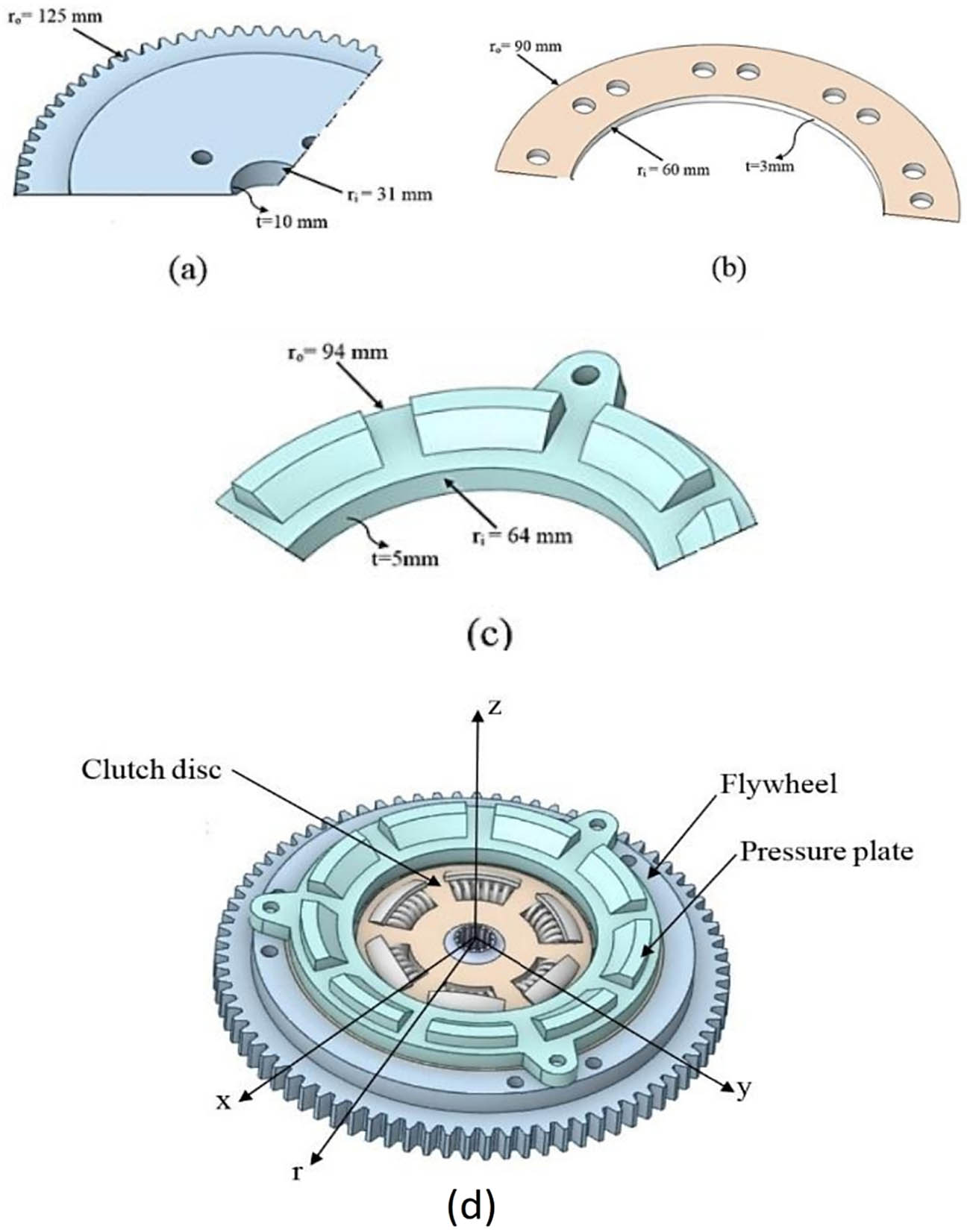
Dimension’s clutch components: (a) flywheel, (b) friction material, (c) pressure plate, and (d) adjusted shape.
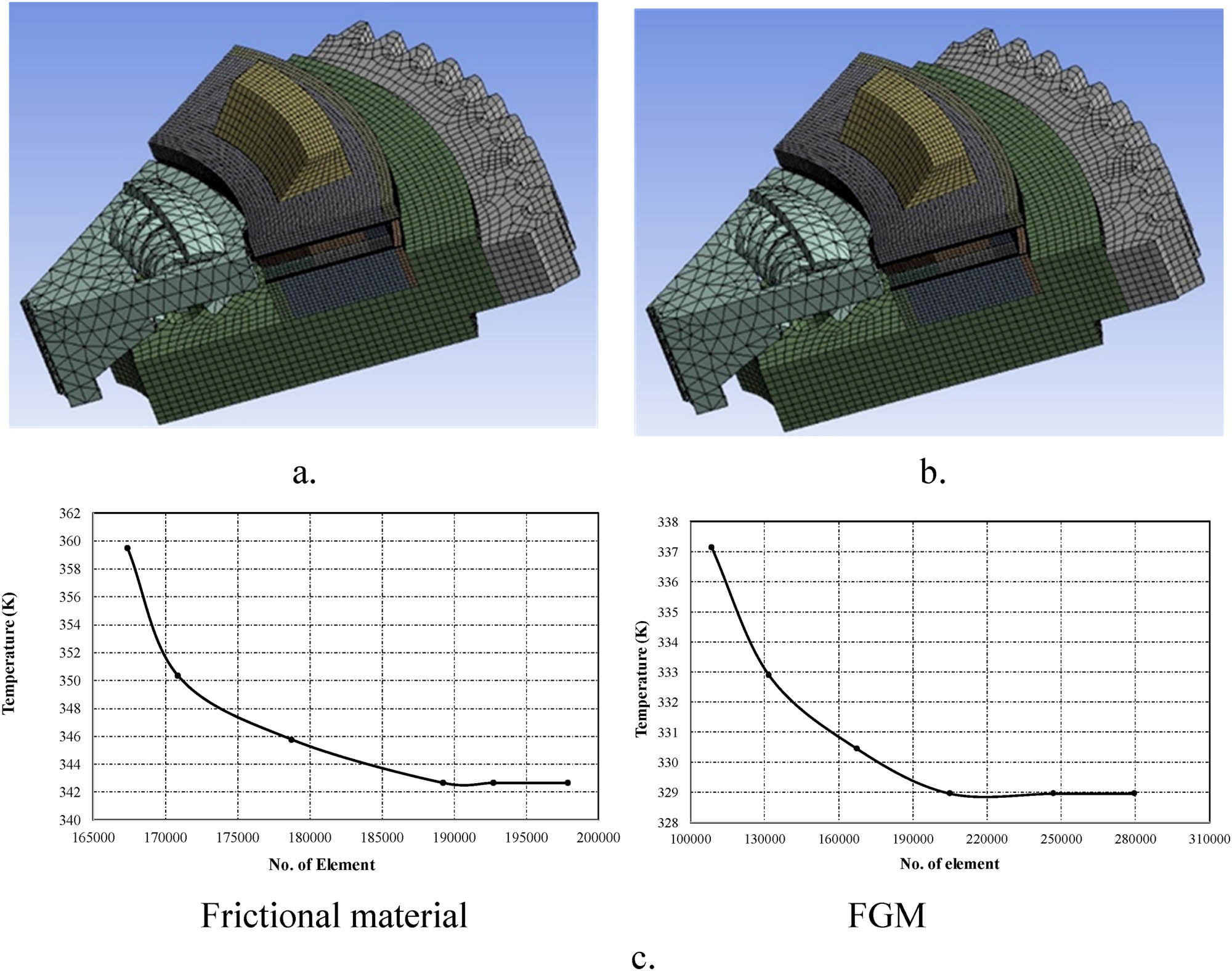
Optimal mesh for the clutch system using (a) FGM, (b) composite material, and (c) the grid independence tests for frictional and FGM materials.
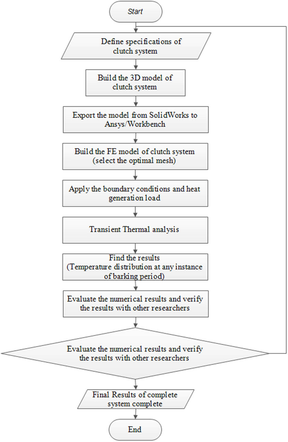
Flowchart to build the 3D FEM for the clutch system.
Mesh properties
| Material | FGM | Frictional materials |
|---|---|---|
| Element type | Hexa + tetra | Hexa + tetra |
| Nodes number | 1097469 | 848652 |
| Element number | 204956 | 189242 |
| Skewness | 7.0968 × 10⁻² | 6.1768 × 10⁻² |
Flywheel and pressure plate’s work conditions and material properties [26]
| Parameter | Value | Parameter | Value |
|---|---|---|---|
| Density for pressure plate, flywheel, and axial cushion [kg m−3] | 7,200 | Specific heat for pressure plate, flywheel, and axial cushion [J kg−1 K−1] | 400 |
| Conductivity for pressure plate and flywheel [W m−1 K−1] | 56 | Initial temperature [K] | 300 |
| Maximum angular slipping speed [rad s−1] | 555 | Torque [N m] | 176 |
Two types of frictional materials are used for the frictional facing of the clutch disk in this numerical analysis. The first one is the FGM, which consists of Sic-Al, as in the previous two-dimensional model, the number of layers is three, and the material power index (k) value is 0.5 (the layer 1 (friction layer) is 57.73% Al and 43.27% Sic), (the layer 2 (medium layer) is 81.56% Al and 18.44% Sic) and (the layer 3 (free layer) is 100% Al). The distribution of the materials for each layer is listed in Table 3 [25]. However, the second one is the commercial frictional materials VH-03 and HDS57; their properties are listed in Table 4.
Material properties of Al and Sic materials
| Material | Al | Sic |
|---|---|---|
| Friction coefficient | 0.47 | 0.6 |
| Specific heat (J kg−1 K−1) | 923.5 | 750 |
| Thermal conductivity (W m−1 K−1) | 160 | 120 |
| Density (kg m−3) | 2,770 | 3,100 |
Material properties of VH-03 and HDS57 materials
| Material | VH-03 | HDS57 |
|---|---|---|
| Friction coefficient | 0.42 | 0.53 |
| Specific heat (J kg−1 K−1) | 1,378 | 1,364 |
| Thermal conductivity (W m−1 K−1) | 0.33 | 0.23 |
| Density (kg m−3) | 1,950 | 1,700 |
2.2 Thermo-mechanical problem
The combination of engineering examinations and physics analysis is used to address engineering design issues involving thermal and thermoelastic models. The thermal–mechanical coupling analysis involves a single FE environment constructed independently, enabling the identification of the coupled material physics solution [26]. The simulation addresses the thermo-elastic problem of contact pressure by analyzing the temperature field and using Hook’s law solution, addressing two coupled issues simultaneously [27]:
and the equation of the equilibrium is
In order to compute the friction-generated heat, it will use elastic analysis to find the contact pressure and apply thermal load in the transient heat conduction model. Then, determine the thermal stresses using the temperature distribution and analyze the new temperature distribution if the following equation holds:
Figure 6 shows the main steps used to conduct the numerical analysis, including elastic contact, to find the thermal stresses and pressure distribution. In addition, the transient thermal investigation for temperature distribution during heating operation was made [28].
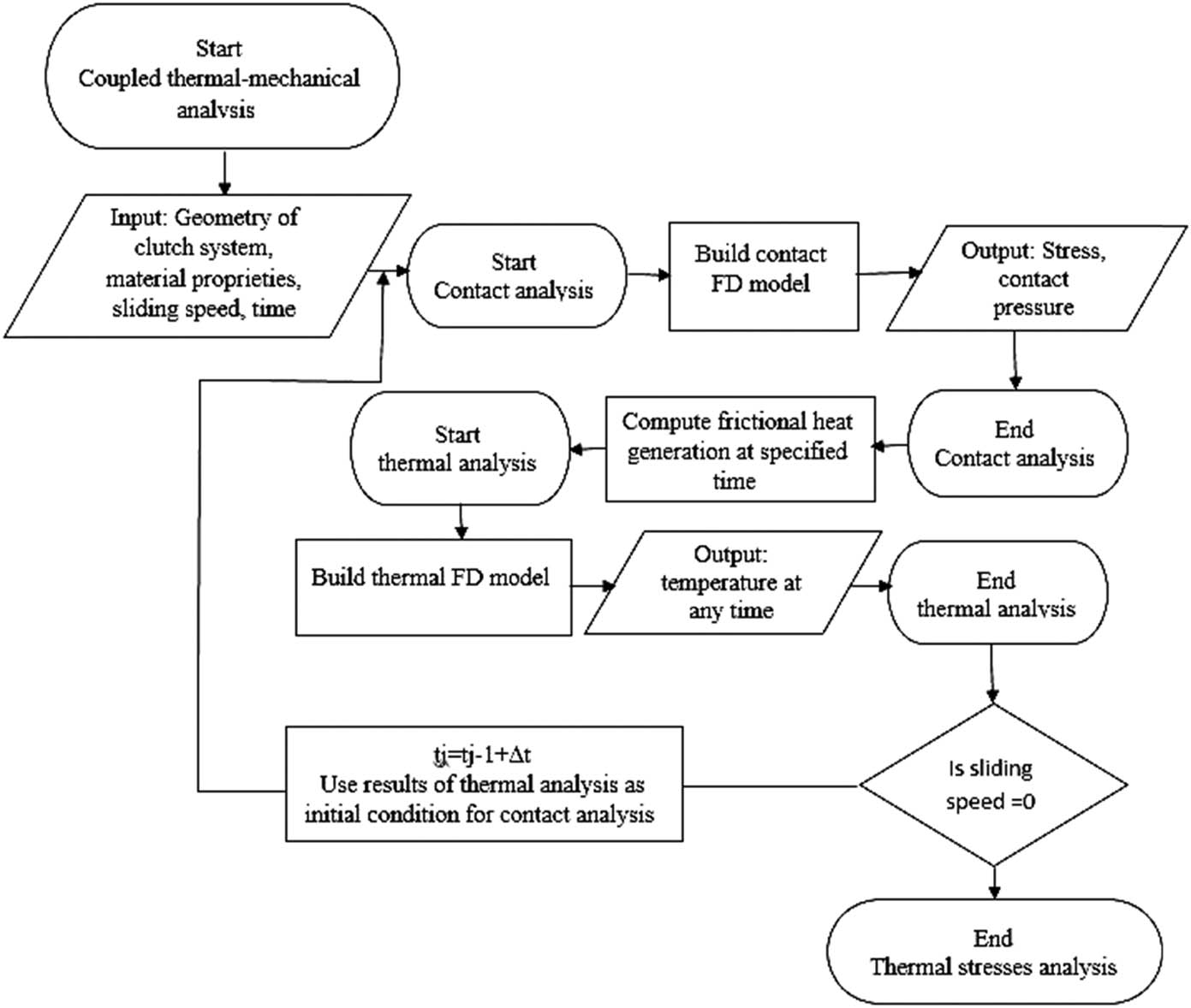
Flowchart of the numerical simulation of the coupled thermoelastic problem.
The other assumptions of the FE model can be listed as follows:
When two surfaces (1 and 2), as shown in Figure 7, are in the contact state [29]:
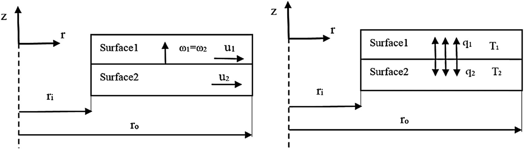
The Contact model for the clutch system.
Two surfaces (1 and 2) are adiabatic when there is no contact between them:
The two-dimensional axisymmetric FE model can be used, as shown in Figure 8, and restricting the flywheel’s backside in the elastic model is illustrated in Figure 9. The PLANE55 element type was chosen for the thermal FEM. This element has four nodes, and its temperature is thought to be its lone degree of freedom. In contrast, the coupling issue in the clutch model is represented by the PLANE13 element in the elastic FEM. Up to four degrees of freedom are available to this type of element. Additionally, each element has four nodes, the same number as the element chosen for the thermal problem. There are three levels of flexibility in the case problem. Temperature and radial and circumferential deformations are these degrees of freedom. The Conta172 element is used for the frictional contact surfaces.
FE models of dry clutch components with the boundary conditions.
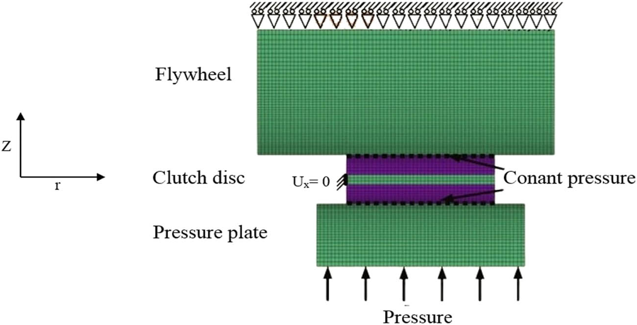
FE model of elastic problem with boundary conditions.
Figure 10 shows the validation of current numerical solutions with experimental approaches by Nasr et al. [30]. The match ratio of maximum surface temperature during the sliding process reached more than 94.8%. Deviations from the experimental curve appeared, and this is mainly due to the fact that, in numerical analysis, it is assumed that the exchange of heat occurs between the lining and its surroundings on the borders of contact; hence, lower temperatures occur at the lining of these sites. This is also due to the violent fluctuations of the frictional torque at the end of the engagement process. The parameters of analysis were 1,200 rpm speed and 4.5 kg m. From an engineering application perspective, the validity of the numerical model was validated with an experimental approach.
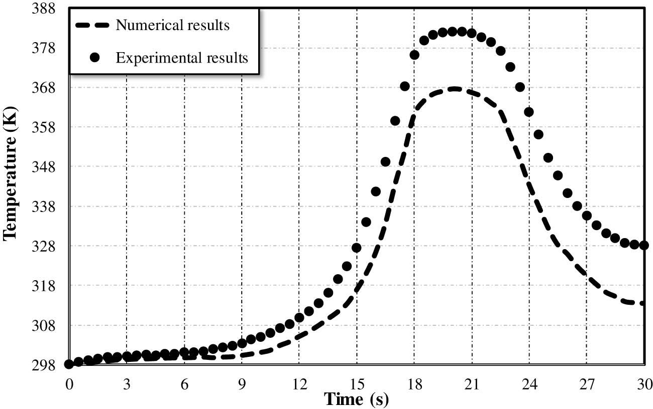
Comparison between numerical and experimental results.
3 Results and discussions
This section will present the most important results obtained using the developed FEMs (2D and 3D) for analyzing the thermal and thermal–elastic behaviors of the friction clutch system during the engagement period using different friction materials. The results highlighted the behavior of the clutch system using the FGM as an alternative friction material.
Figure 11 shows the variation of maximum surface temperatures using the FGM clutch disk under different uniform wear and pressure conditions, with a slip period of 0.4 s. It can be noted that the thermal effect on the clutch system increased dramatically under the uniform pressure assumption compared with the uniform wear assumption at any time in the sliding period. The temperature difference between the two cases grew at any instance period until the halfway point of a sliding period when the highest temperatures occurred. After this point, the temperature difference diminished until the sliding time was over.
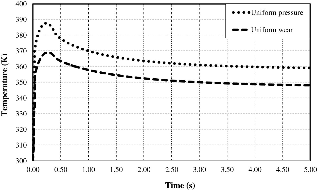
Variation of maximum temperatures using FGM clutch disk under different conditions.
Figures 12 and 13 illustrate the variation of maximum temperatures using different friction materials under uniform pressure and wear assumptions. FGM showed excellent thermal behavior compared with the other frictional materials. The FGM has better characteristics to dissipate heat (e.g., at 1 s) compared to the VH-03 and HDS57 materials under both assumptions. This result is due to the good thermal properties of the FGM material, which lead to an increase in the rate of heat transfer by conduction and finally a lower surface temperature within the allowable limit.
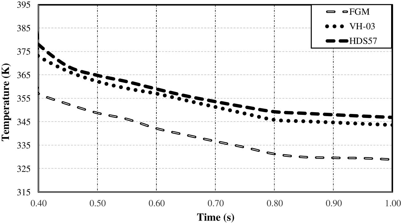
Variation of maximum temperature using different friction materials under uniform pressure assumption.
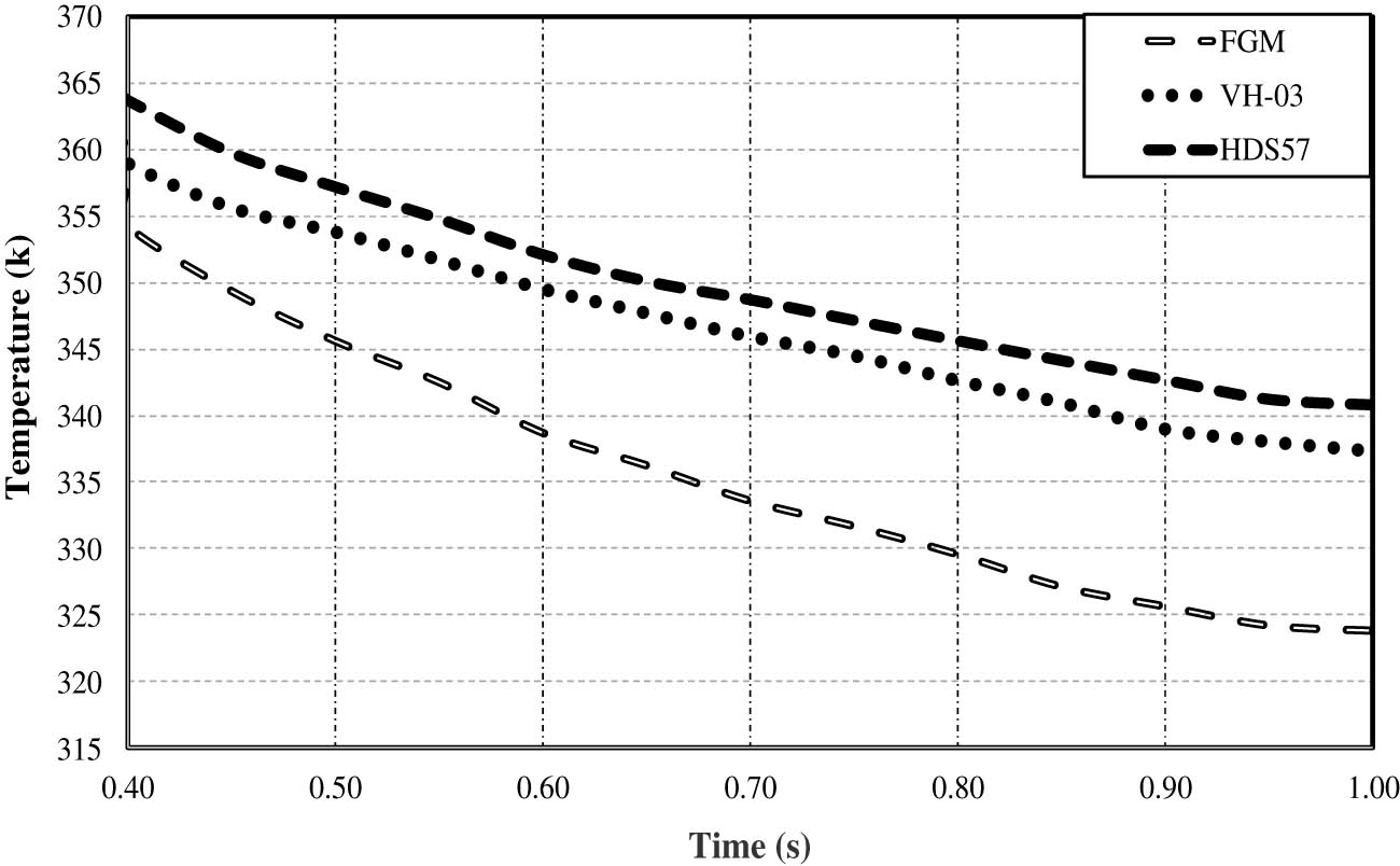
Variation of maximum temperature using different friction materials under uniform wear assumption.
Figure 14 presents the temperature distribution of the clutch system using the 3D FEM using FGM under uniform pressure and uniform wear assumptions. These results were captured when the highest surface temperature value occurred (t s = 0.2 s) during the engagement.
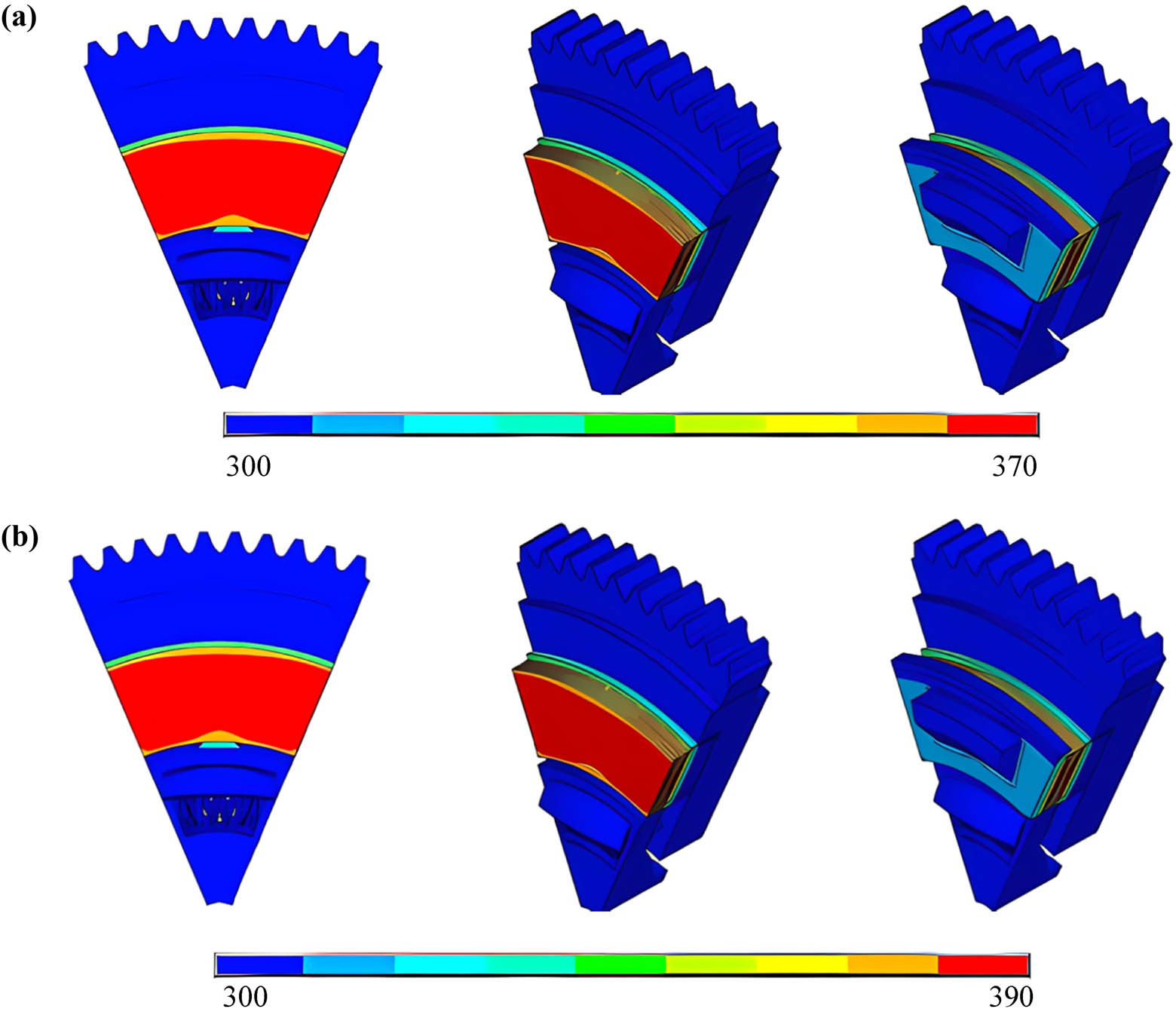
Temperature distribution of the clutch system using FGM at 0.2 s under (a) uniform wear and (b) uniform pressure.
The second part introduced the variation of the maximum contact pressure between the contacting elements (clutch disk and pressure plate, clutch, disk, and flywheel) under the uniform pressure assumption using different frictional materials.
Figures 15 and 16 demonstrate the variation of the maximum contact pressure on clutch surfaces between the clutch disk and pressure plate and between the clutch disk and flywheel during the slipping time using different friction materials. It can be seen that the values of the contact pressure on the pressure plate side are higher than those on the flywheel side when using the VH-03 and HDS57 friction materials. However, it obtained approximately the same level of contact pressure for both sides (pressure plate and flywheel) when using the FGM friction material. The maximum values of the contact pressures when using the FGM on the flywheel and pressure plate sides are found to be 0.559 and 0.56 MPa, respectively. It can be observed that the behaviors of the contact pressure are approximately similar when using the VH03 and HDS 57 friction materials. On the other hand, it is very clear that the level of contact pressure decreased remarkably when using the FGM material instead of the other friction materials. The reductions in the contact pressure were approximately 77 and 78% when using the FGM material instead of the VH-03 and the HDS-57 materials.
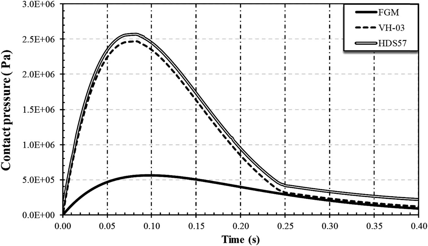
Variation of maximum contact pressure on the pressure plate side during the slip period at the interface.
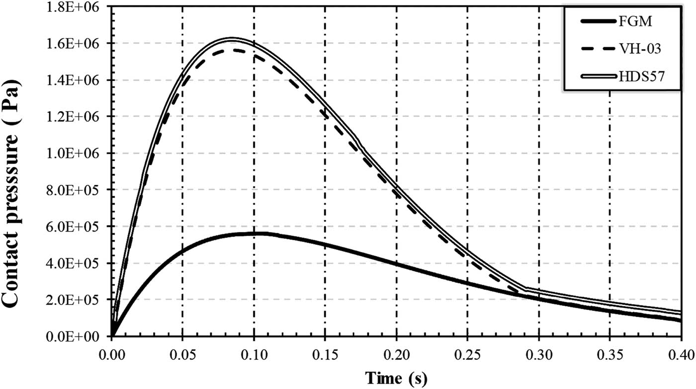
Variation of maximum contact pressure on the flywheel side during the slip period at the interface.
4 Conclusions and remarks
This research article spotlights the numerical solutions to the thermal and thermo-mechanical problems of the dry friction clutch during a single engagement. Axisymmetric and 3D FEMs were built to represent the numerical simulation of the clutch system during the beginning of the engagement (sliding phase). The effect of using different frictional facings (FGM, HV-03, and HDS57) on the thermal performance of the clutch system was examined deeply. Based on the obtained results, it can be summarized as follows:
Clutch disk surface temperatures increase under uniform pressure higher than under uniform wear during sliding phases. When slip time is short, the difference between them grows until the maximum temperature occurs (in this case, the midtime of the sliding period). Then, the difference between them decreases very slowly. The results proved that using FGM enhanced the improvement of the thermal behavior of the friction clutch system, as the level of temperatures decreased due to the good thermal properties of this material compared to the currently available commercial friction materials. The heat dissipation rate has increased dramatically due to the high thermal conductivity of the FGM compared to the other friction materials. The other important point directly connected to reducing the generated heat level is the value of the contact pressures, where the frictional surfaces made of FGM material showed lower contact pressure (approximately 77%) compared to the VH-03 and HDS57 materials. The new 3D FEM is considered a promising numerical tool that can be used to investigate many complex problems in the future, such as asymmetric thermal load, surface roughness, hot spots, and flash temperature.
The novel point of this research work is to build a numerical model based on the FEM that is capable of overcoming the difficulties and obstacles faced by the previous models for analyzing the performance of the frictional clutch systems during the period of sliding and under the influence of thermal and structural loads. This developed model can find the temperature distributions at any moment during the sliding period, as well as find the stresses to which the friction system is exposed. Another point worth noting is that this 3D numerical model for the friction clutch system includes all the complexities of geometries of each part of the friction system. This developed model can be used to find the solution to the coupling problem (thermal and structural) at the same time and overcome the obstacles facing previous models, such as the possibility of studying and analyzing other important problems that were difficult to study previously, such as the wear, surface roughness, special friction material (e.g. FGM), and asymmetric load problems.
-
Funding information: Authors state no funding involved.
-
Author contributions: All authors have accepted responsibility for the entire content of this manuscript and consented to its submission to the journal, reviewed all the results and approved the final version of the manuscript. NAJ: methodology, formal analysis, investigation, writing – review & editing. IYH: Formal analysis, funding acquisition, resources, writing – review & editing. OIA: Investigation, project administration, writing – review & editing. MNM: Investigation, writing – review & editing, validation.
-
Conflict of interest: Authors state no conflict of interest.
References
[1] Sahu M. Finite element analysis of single plate clutch by using ANSYS. Int J Res Appl Sci Eng Technol. 2018;6:1337–46.10.22214/ijraset.2018.6195Search in Google Scholar
[2] Samir S, Emmanuel B, Jérôme F, Matthieu M. Numerical and experimental study of automotive riveted clutch discs with contact pressure analysis for the prediction of facing wear. Finite Elem Anal Des. 2011;47(2):129–41.10.1016/j.finel.2010.08.007Search in Google Scholar
[3] Akhtar MMJ, Abdullah OI, Schlattmann J. Transient thermoelastic analysis of dry clutch system. Mach Des. 2013;5(4):141–50.10.1155/2013/495918Search in Google Scholar
[4] Yang LK, Li HY, Ahmadian M. Analysis of the influence of engine torque excitation on clutch judder. J Vib Control. 2015;23(4):645–55.10.1177/1077546315582291Search in Google Scholar
[5] Menday M, Rahnejat H. Friction-facing characteristics and the clutch take up judder phenomenon with manual transmission. Tribology and Dynamics of Engine and Powertrain: Fundamentals, Applications and Future Trends. UK: Woodhead Publishing Ltd; 2010. p. 680–702.10.1533/9781845699932.2.680Search in Google Scholar
[6] Pei YC, Chatwin C, He L. A thermal boundary control method for a flexible thin disk rotating over critical and supercritical speeds. Meccanica. 2017;52(2):383–401.10.1007/s11012-016-0418-ySearch in Google Scholar
[7] Tonazzi D, Massi F, Baillet L. Experimental and numerical analysis of frictional contact scenarios: from macro stick-slip to continuous sliding. Meccanica. 2015;50(3):649–64.10.1007/s11012-014-0010-2Search in Google Scholar
[8] Centea D, Rahnejat H, Menday MT. Non-linear multibody dynamic analysis for the study of clutch torsional vibrations (judder). Appl Math Model. 2001;25(3):177–92.10.1016/S0307-904X(00)00051-2Search in Google Scholar
[9] Yang Q, Stainier L, Ortiz M. A variational formulation of the coupled thermo-mechanical boundary-value problem for general dissipative solids. J Mech Phys Solids. 2006;54:401–24.10.1016/j.jmps.2005.08.010Search in Google Scholar
[10] Bagri A, Eslami MR. Generalized coupled thermoelasticity of disks based on the Lord–Shulman model. J Therm Stresses. 2004;27(8):691–704.10.1080/01495730490440127Search in Google Scholar
[11] Abdullah OI, Schlattmann J, Al‐Shabibi AM. Thermomechanical analysis of the dry clutches under different boundary conditions. Tibology in Industry. 2014;36(2):172–80.Search in Google Scholar
[12] Jenan SS, Ihsan YH, Abdullah OI. Finite element simulation of thermal behavior of dry friction clutch system during the slipping period. Dissertation. Mechanical Department, College of engineering; 2019.Search in Google Scholar
[13] Abdullah OI, Abd Al-Sahb W, Al-Shabibi A. Finite element analysis of transient thermoelastic behavior in multi-disc clutches. Tribologia. 2014;5:9–24; Nasr AJ, Ihsan YH, Oday IA. Thermal and thermoelastic problems in dry friction clutch: A comprehensive review. 2021;50(8): 7855–78.Search in Google Scholar
[14] Mahir HM, Dheyaa EK, Oday IA, Josef S. Numerical analysis of thermal problem in dry friction clutches based on the interactive design approach. Int J Interact Des Manuf. 2020;14:1091–101.10.1007/s12008-020-00660-1Search in Google Scholar
[15] Stojanovic N, Abdullah OI, Rakisheva ZB, Lattieff FA, Hashim ET. The effect of applied pressure function on thermo-elastic problem in the dry friction clutches. J Fail Anal Prev. 2020;20(6):2145–52.10.1007/s11668-020-01031-4Search in Google Scholar
[16] Faidh-Allah MH. The temperature distribution in friction clutch disc under successive engagements. Tribol Ind. 2018;40(1):92–9.10.24874/ti.2018.40.01.08Search in Google Scholar
[17] Chen J, Jiali Yu, Yubing G. A new multi-physics coupled method for the temperature field of dry clutch assembly. Appl Sci. 2023;13(20):11165.10.3390/app132011165Search in Google Scholar
[18] Padmanabhan S, Vinod Kumar T, Sendil DK, Gowsikan V, Akshay BK, Hitesh KSS. Investigation of structural and thermal analysis of clutch facings with different friction materials. Mater Today: Proc. 2023;92:98–105.10.1016/j.matpr.2023.03.757Search in Google Scholar
[19] Liu YAU, Sun YAU, Gao ZAU, Ye FAU, Tang PPY. Transient temperature characteristics of friction clutch disc considering thermal contact conductance under sliding conditions. Friction. 2023;11:2253–63.10.1007/s40544-022-0724-4Search in Google Scholar
[20] Haojie H, Zhaoquan L. Tribo-thermal simulation study of AMT dry clutch assembly under the continuous sliding grinding condition. J Phys Conf. 2023;2587:1–6.10.1088/1742-6596/2587/1/012035Search in Google Scholar
[21] Chao X, Guiyu W, Shijie H, Yong Z, Jie T. Finite element analysis of thermal load characteristics of dry dual clutch. J Phys Conf Ser. 2021;1748:1–5.10.1088/1742-6596/1748/5/052047Search in Google Scholar
[22] Abdullah OI, Schlattmann J. Finite element analysis of temperature field in automotive dry friction clutch. Tribol Ind. 2012;34(4):206–16.Search in Google Scholar
[23] Howon S, Chunhua Z, Wonsik L, Suk WC, Sangchull H. The results have shown a good agreement with the experimental work. Vehicle Power and Propulsion Conference (VPPC). IEEE; 2011.Search in Google Scholar
[24] Abdullah OI, Schlattmann J. Thermal behavior of friction clutch disc based on uniform pressure and uniform wear assumptions. Friction. 2016;4:228–37.10.1007/s40544-016-0120-zSearch in Google Scholar
[25] Jabbar NA, Hussain IY, Abdullah OI. Thermal analysis of functionally graded dry clutch disc subjected to characteristic parameters effects. Integrated Computer Technologies in Mechanical Engineering Conference 2022. Springer; 2023.10.1007/978-3-031-36201-9_28Search in Google Scholar
[26] Ali IAI, Asiri S. Thermal and mechanical analyses of dry clutch disk made of functionally graded material. Mater Res Express. 2022;9(4):1–29.10.1088/2053-1591/ac6150Search in Google Scholar
[27] Harish K, Kumar YD. Optimization of friction clutch for various friction materials. Int J Res. 2017;4(17):3493–8.Search in Google Scholar
[28] Oday IA, Wassan, AA, Abdullah MA. Thermoelastic analysis of multi-disc clutches using finite element method. Tribologia. 2014;257(5):9–24.Search in Google Scholar
[29] Nasr AJ, Ihasn, YH, Oday IA. Numerical simulation of dry friction clutch thermal behavior with different friction materials. 2023;2651(1):1–9.10.1063/5.0105422Search in Google Scholar
[30] Jabbar NA, Hussain IY, Abdullah OI, Mohammed MN. An Experimental investigation and numerical analysis of the thermal behavior of a clutch system using the frictional facing of functionally graded materials. Designs. 2023;7:125.10.3390/designs7060125Search in Google Scholar
© 2024 the author(s), published by De Gruyter
This work is licensed under the Creative Commons Attribution 4.0 International License.
Articles in the same Issue
- Research Articles
- Flutter investigation and deep learning prediction of FG composite wing reinforced with carbon nanotube
- Experimental and numerical investigation of nanomaterial-based structural composite
- Optimisation of material composition in functionally graded plates for thermal stress relaxation using statistical design support system
- Tensile assessment of woven CFRP using finite element method: A benchmarking and preliminary study for thin-walled structure application
- Reliability and sensitivity assessment of laminated composite plates with high-dimensional uncertainty variables using active learning-based ensemble metamodels
- Performances of the sandwich panel structures under fire accident due to hydrogen leaks: Consideration of structural design and environment factor using FE analysis
- Recycling harmful plastic waste to produce a fiber equivalent to carbon fiber reinforced polymer for reinforcement and rehabilitation of structural members
- Effect of seed husk waste powder on the PLA medical thread properties fabricated via 3D printer
- Finite element analysis of the thermal and thermo-mechanical coupling problems in the dry friction clutches using functionally graded material
- Strength assessment of fiberglass layer configurations in FRP ship materials from yard practices using a statistical approach
- An enhanced analytical and numerical thermal model of frictional clutch system using functionally graded materials
- Using collocation with radial basis functions in a pseudospectral framework to the analysis of laminated plates by the Reissner’s mixed variational theorem
- A new finite element formulation for the lateral torsional buckling analyses of orthotropic FRP-externally bonded steel beams
- Effect of random variation in input parameter on cracked orthotropic plate using extended isogeometric analysis (XIGA) under thermomechanical loading
- Assessment of a new higher-order shear and normal deformation theory for the static response of functionally graded shallow shells
- Nonlinear poro thermal vibration and parametric excitation in a magneto-elastic embedded nanobeam using homotopy perturbation technique
- Finite-element investigations on the influence of material selection and geometrical parameters on dental implant performance
- Study on resistance performance of hexagonal hull form with variation of angle of attack, deadrise, and stern for flat-sided catamaran vessel
- Evaluation of double-bottom structure performance under fire accident using nonlinear finite element approach
- Behavior of TE and TM propagation modes in nanomaterial graphene using asymmetric slab waveguide
- FEM for improvement of damage prediction of airfield flexible pavements on soft and stiff subgrade under various heavy load configurations of landing gear of new generation aircraft
- Review Article
- Deterioration and imperfection of the ship structural components and its effects on the structural integrity: A review
- Erratum
- Erratum to “Performances of the sandwich panel structures under fire accident due to hydrogen leaks: Consideration of structural design and environment factor using FE analysis”
- Special Issue: The 2nd Thematic Symposium - Integrity of Mechanical Structure and Material - Part II
- Structural assessment of 40 ft mini LNG ISO tank: Effect of structural frame design on the strength performance
- Experimental and numerical investigations of multi-layered ship engine room bulkhead insulation thermal performance under fire conditions
- Investigating the influence of plate geometry and detonation variations on structural responses under explosion loading: A nonlinear finite-element analysis with sensitivity analysis