Design and evaluation of powered lumbar exoskeleton based on human biomechanics
-
Qingqing Wang


Abstract
Objectives
In view of the gradual rejuvenation and acceleration of lumbar spondylosis, a wearable powered lumbar exoskeleton based on a 6-SPU/SP parallel mechanism is designed based on the rehabilitation treatment method of lumbar forward flexion/extension, left/right lateral flexion and rotation.
Methods
First, the changes in human lumbar muscles are analyzed based on human biomechanics, and then the prototype design of the powered lumbar exoskeleton is implemented, including the mechanical mechanism design, and hardware module design. Finally, the simulation experiment of muscle force and output sensitivity test in the resistive mode are conducted.
Results
The simulation results show that the external oblique muscle can be relieved about 20 % and the iliopsoas muscle can be decreased by 33 % when wearing the powered lumbar exoskeleton in the lateral flexion. The pressure sensors can measure the output force of each actuator in real-time when the resistance force reaches the set value of 15 N at the resistive model.
Conclusions
The results show that the powered lumbar exoskeleton can assist the human lumbar spine in rehabilitation training of traction, forward flexion and extension, left and right lateral flexion, and rotation. This research provides new ideas for future clinical research.
Introduction
The lumbar spine is a crucial part of human movement, and it has a key role in load-bearing, shock absorption, protection and movement [1]. Lumbar spondylosis is a common name for diseases of the lumbar spine, typically accompanied by back pain. The prevalence rate among adults is as high as 65–80 %, and it is affecting the younger populations. There are usually two treatments for lumbar spondylosis: surgical and non-surgical. Surgical treatment can pose an additional risk. In the nonsurgical treatment, lumbar traction is one of the most common treatments for low back pain by reducing compression [2], 3]. Another basic method of treating low back pain is lumbar rehabilitation training. It can improve the mobility and stability of the lumbar spine and accelerate recovery [4], 5].
Trunk exoskeletons represent a relatively new technology with significant potential for human rehabilitation, assistance and enhancement. Recently, lumbar exoskeletons are mainly used in industrial applications, such as hybrid assisted limb (HAL) for care support [6], mobile wearable waist assist robot [7], and power-assisted exoskeleton [8]. These types of exoskeleton tend to be larger and more suitable for industrial applications.
There are also few types of robotic braces for rehabilitation. Li X et al. applied the 4-SPS/SP parallel mechanism to a new wearable back-support exoskeleton, which can relieve the low back pain [9]. Each of the four limbs consisted of a spherical-prismatic-spherical (SPS) structure. Theoretical analysis has verified that it can achieve 4 degrees of freedom of lumbar movement. However, due to the redundant degrees of freedom in device configuration and the flexible design of waist ring, the stability of the wearable back-support exoskeleton needs further improvement to avoid changing the actual direction of traction force. Qi K et al. designed a wearable waist rehabilitation robot with 2-PUU/2-PUS parallel mechanism [10]. Each of the two PUU limbs consisted of one prismatic joint (P) and two universal joints (U). It has four degrees-of-freedom (DOF) to comply with waist movements, but it is currently only at the theoretical analysis stage. The above analysis shows that there is still room for improvement in the exploration of lumbar exoskeletons based on parallel mechanisms. Lumbar traction and rehabilitation training treatments clinically are mostly carried out by rehabilitation therapists or large equipment such as traction beds, and the treatment costs are high. The incidence of lumbar spondylosis has shown an increasing trend year by year and is affecting younger populations. Therefore, it is of great clinical value to develop a multi-degree-of-freedom lumbar rehabilitation exoskeleton that has preventive and therapeutic effects.
In this paper, the proposed powered lumbar exoskeleton mainly focuses on rehabilitation training of the lumbar in three anatomical planes and traction along the lumbar vertical axis. In order to realize the lumbar spine rehabilitation training with 4 DOF, this paper is arranged as follows. Firstly, the range of motion of the lumbar spine is described, and the candidate for the mechanism structure is selected. Next, the mechanical design and hardware design of powered lumbar exoskeleton are implemented. Finally, the simulation of muscle force and the output sensitivity test in the resistive mode are conducted.
Lumbar spine motion and mechanism analysis
The human lumbar spine supports the weight of the human body. It allows movement and flexibility. The muscles of the waist work together to produce four-dimensional muscle contraction, relaxation and rotation. This means that the lumbar spine has stretching, flexion and extension, lateral flexion and rotation functions. The movement of the lumbar spine is illustrated in Table 1. Referring to the movement rehabilitation mechanism of the lumbar spine, the range of motion and movement characteristics are defined, as shown in Table 1.
Motion characteristics and range of lumbar spine.
| Axis of rotation | Joint movement | Range of motion |
|---|---|---|
| X axis | Left/right lateral bending | −25°∼25° |
| Y axis | Flexion/extension | −25°∼25° |
| Z axis | Left/right rotation | −15°∼15° |
Prototype design
Mechanism architecture
From the perspective of biomechanics, this paper carries out mechanical equivalent modeling of the human spine, which is equivalent to a cylindrical joint (C) and a spherical joint (S). It is ensured that the mobility of the human lumbar spine is fully considered in the proposed design of the powered lumbar exoskeleton. Based on the establishment of equivalent human lumbar spine model and preliminary evaluation of a musculoskeletal model, the powered lumbar exoskeleton configuration is determined. The 6-SPS/SP equivalent mechanism of the powered lumbar exoskeleton includes a mobile ring, a base ring and 6 SPU branch chains with the same structure but different lengths, connecting the mobile ring and base ring.
The mechanism design, shown in Figure 1, is used to achieve the desired degrees-of-freedom while meeting the unique needs of rehabilitation. The two rings are designed by Blender software (Blender Institute, Netherlands), which can ensure that the two rings conform to the physiological curvature of the human body without scanning the human body through 3D software. The two rings provide support to the lumbar and pelvis without slipping and restricting the user’s breathing. Lateral adjustment modules and longitudinal adjustment modules are added to increase adaptability, which can meet the needs of users of different sizes. Additionally, the force buffer module is designed to absorb part of the external force, thereby avoiding secondary damage to the human spine and improving the comfort during wearing.
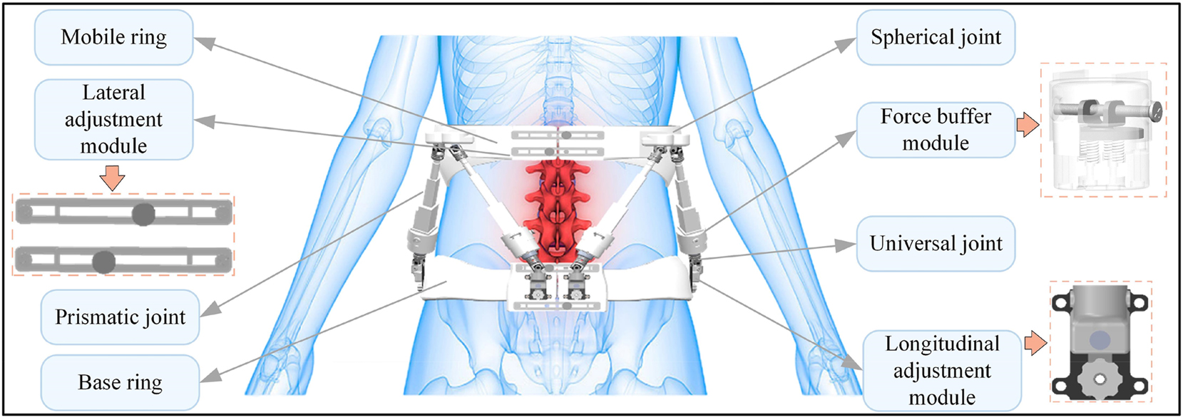
Proposed design of powered lumbar exoskeleton.
Hardware design
The hardware design system of the powered lumbar exoskeleton is shown in Figure 2, which consists of system control board, external board, and information processing module. First, the battery pack (QSO-1206, 12 V) can provide power directly to the motor control board, and also provide power to the communication module and information processing module through voltage converter. Each motor unit has one linear motor (L16-100-150-12-P, RS Company, Shanghai, China) with a potentiometer. The potentiometer can measure the length of the actuator. The stroke is 100 mm, the reduction ratio is 150/1, the power supply voltage is 12 V, the peak power point is 200 N, the reverse driving force is 102 N, and the maximum speed is 8 mm/s. The pressure sensor (DYZ-101, DA YSENSOR, China) at the end of the actuator can measure the propulsion force. Two IMUs (BWT901CL, WIT, Shenzhen, China) detect the relative angles between the front of mobile ring and base ring.
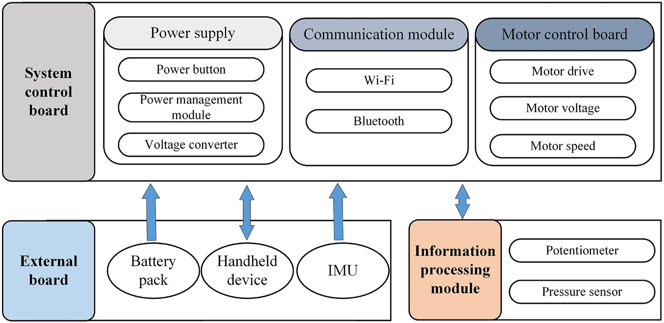
The hardware of powered lumbar exoskeleton.
In order to meet the need of different occasions for low back pain, we set the powered lumbar exoskeleton to have different training modes, namely passive mode, follow-up mode, and resistive mode. In the passive mode, the powered lumbar exoskeleton is used as a power device in order to pull the waist to move. In the follow-up mode, the powered lumbar exoskeleton acts as an assistive device to assist the wearer’s movement. In the resistive mode, the powered lumbar exoskeleton is used to provide resistance for training. A handheld device allows the user to select training motions (i.e., flexion/extension, left/right lateral bending, rotation and traction), adjust training parameters (i.e., force and angle) and switch training modes (resistive mode, follow-up mode and passive mode). It transmits commands to the system control board via Bluetooth. Additionally, the force, angle and length of the actuator can be transmitted to a PC in real time via Wi-Fi.
Display of prototype
The prototype of powered lumbar exoskeleton is shown in Figure 3. Mobile ring and base ring are placed on lumbar and pelvis respectively. The entire control module is integrated and hung on the back when wearing. The whole prototype is 2.5 kg, it is small and lightweight compared to backpack-style exoskeleton such as mobile wearable waist assist robot [7].
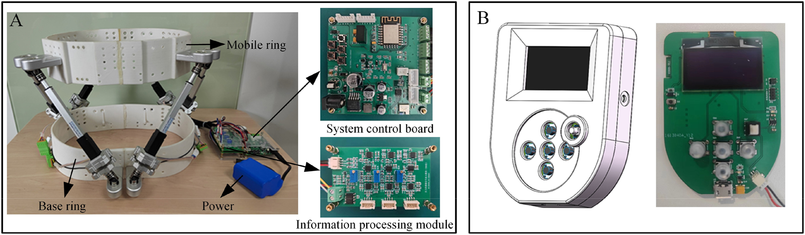
Prototype of the powered lumbar exoskeleton. Detailed display of the prototype model (A), handheld device (B).
Experiments
In this section, the simulation experiment of muscle force is performed to determine the effect on the muscle release in the passive mode. Second, an output sensitivity test of the powered lumbar exoskeleton is implemented at different motion directions in the resistive mode.
The simulation experiment of muscle force
Experiment environment setup
There are many human musculoskeletal models in OpenSim (4.3 Stanford), and we use the complete full-body lumbar spine model (FELS) [7], 8]. The lumbar spine mechanism (i.e., L1∼L5) and lumbar muscle groups are modeled in detail in FELS. Before the simulation experiment begins, a human-machine interaction model need to be constructed. The powered lumbar exoskeleton is simplified, and the key parameters of the simplified exoskeleton (i.e., the mass, center of mass and inertia of each part) are extracted from the XML file to add to the Bodyset. The entire human-machine interaction model is shown in Figure 4A. The bushing force between the musculoskeletal model and the simplified exoskeleton is set as the spring damping model.
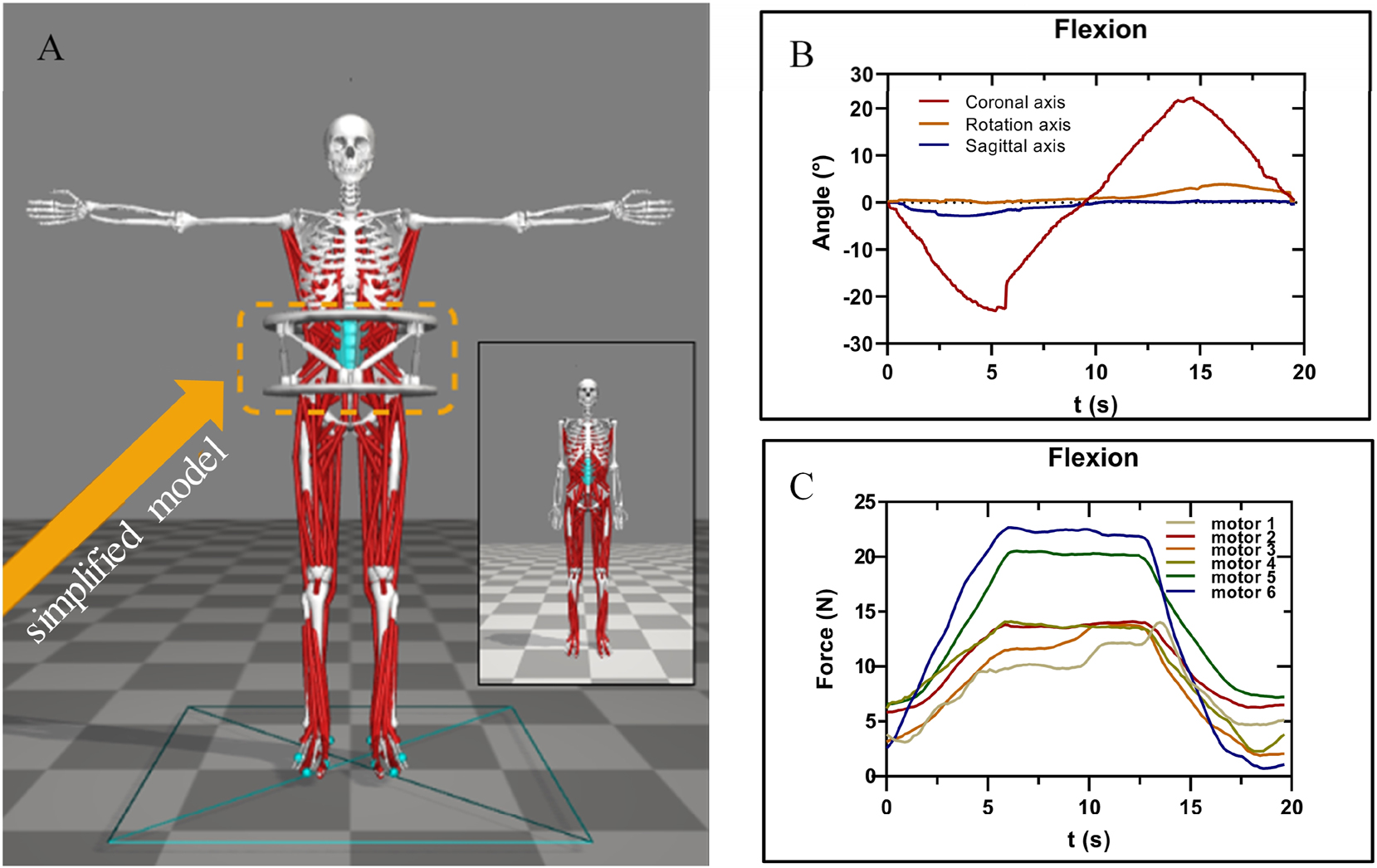
The simulation of muscle force. The full human-machine interaction model (A). The curves of waist movement trajectories in the flexion (B). The curves of driver forces in the flexion (C), and each colour line represented the force of an actuator.
Implementation of simulation step
The waist movement trajectories (flexion/extension, lateral flexion, rotation) and the driver force of each actuator are transmitted by the PC via Wi-Fi in passive mode, and the data are saved for experimental simulation. Waist movement trajectories are set as the desired trajectory. mot file in human-machine interaction mode. The driver force for each actuator is defined by the External Force module to act on the torso. The driver force is directed from the mounting point of the push rod to the direction of elongation of the push rod. The curves of waist movement trajectories and driver forces are shown in Figure 4B and C (e.g. flexion).
When not wearing the exoskeleton, the waist motion trajectory is run to obtain the curves of lumbar joint moments over time in the Inverse Dynamic Tool of OpenSim, and the curves of the muscle force in the waist over time are obtained in the Static Optimization Tool of OpenSim. When wearing the exoskeleton, the drive forces are defined by the External Force module and are acted on the torso, and six stress points are defined on the torso.
Output sensitivity and effectiveness test in the resistive mode
In the sensitivity test, a healthy participant is recruited (age: 22 years old, height: 175 cm, weight: 70 kg), as shown in Figure 5. We conduct a preliminary resistance test with wearing the powered lumbar exoskeleton during the forward flexion, left flexion and left rotation when the resistance is set to 15 N, and feedback signals from six pressure sensors are acquired. In this way, the sensitivity and effectiveness of the resistive mode are preliminarily verified.
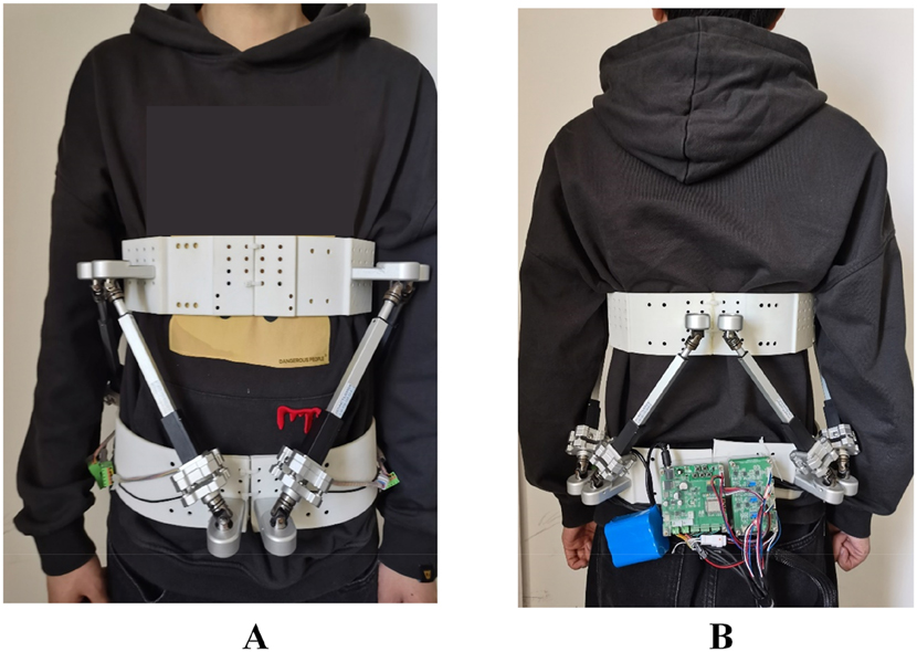
Display of wearing the powered lumbar exoskeleton. The front display of wearing the powered lumbar exoskeleton (A), the back display of wearing the powered lumbar exoskeleton (B).
Results
The effectiveness on muscle release
The muscle forces of the low back muscle groups (i.e., iliopsoas muscle) and abdominal muscle groups (i.e., external oblique muscle) are calculated with or without the powered lumbar exoskeleton.
As shown in Figure 6, the muscle forces of left and right muscles have the same motion patterns. Compared to when no exoskeleton is worn, the muscle force of external oblique muscle with powered lumbar exoskeleton reduces significantly in the rotation (from 36 to 14 N) and lateral flexion (from 140 to 110 N). The muscle force of iliopsoas muscle decreases by about 10 N in the lateral flexion, and has no change in the rotation and flexion. The simulation results show that wearing the powered lumbar exoskeleton can alleviate muscle strain.
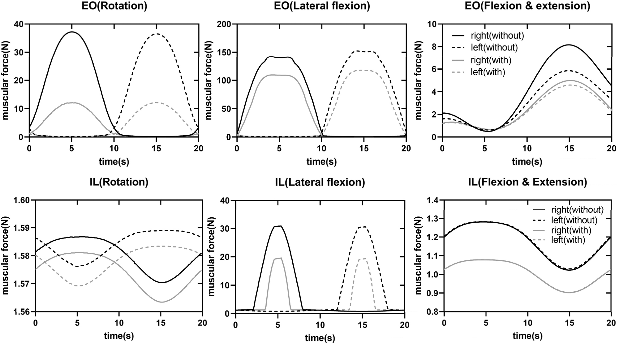
Changes in muscle force in various motion postures with or without powered lumbar exoskeleton. The three figures represent the changes of the muscle forces of the left and right external oblique muscle in three motion posture (rotation, lateral flexion and flexion) in the top row. The three figures represent the changes of the muscle forces of the left and right iliopsoas muscle in three motion posture (rotation, lateral flexion and flexion) in the bottom row. Black colour represents wearing the exoskeleton, gray colour represents not wearing the exoskeleton, solid lines represents the right-side muscles, and dashed lines represents the left-side muscles. EO is the abbreviation for external oblique muscle, IL is the abbreviation for iliopsoas muscle.
Output sensitivity test in the resistive mode
The resistance is set to 15 N in the forward flexion, left lateral flexion and left rotation. When the body’s resistance reaches 15 N, the powered lumbar exoskeleton is driven to move in the opposite direction, as shown in Figure 7. In the forward flexion resistance, the pressures on the motors 4 and 5 are the greatest, indicating that the waist of the human is pushing back. In the left lateral flexion resistance, the pressures on the motors 5 and 6 are the greatest, indicating that the waist of the human is resisting to the right side. In the left rotation resistance, the pressures on the motors 3, 4, and 5 are the greatest, indicating that the waist of the human is resisting to the right rotation.
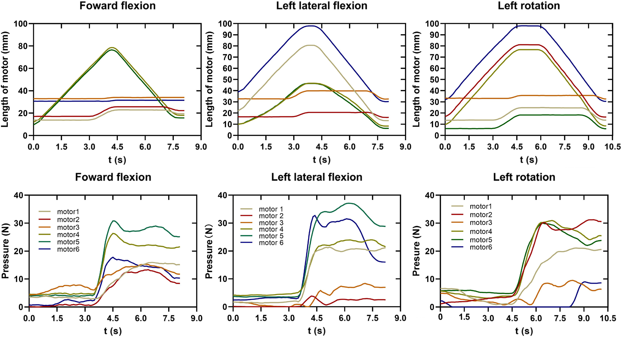
The pressure and length of each motor in the resistive mode. The three figures represent the length of each motor in three motion posture (forward flexion, left lateral flexion and left rotation) in the top row. The three figures represent pressure of each motor in three motion posture (forward flexion, left lateral flexion and left rotation) in the bottom row. Each colour line represents an actuator.
Discussion
The effectiveness on muscle release
From the simulation results shown in Figure 6, it can be observed that wearing the powered lumbar exoskeleton causes significant changes during lateral flexion movements. The muscle force of the back muscles, such as the iliopsoas, decreases by 33 %, and the muscle force of the abdominal muscles, such as the external oblique, decreases by about 20 %. During lateral rotation, the ipsilateral flexor muscles of the lumbar region are more active than the contralateral extensor muscles, and the abdominal muscles are more active than the back muscles. After wearing the exoskeleton, the external oblique muscle shows a significant decrease of about 56 %, while the iliopsoas muscle decreases less.
Although the simulation results tended to align with the functional descriptions in related literature, such as the active participation of flexor muscles while relaxation of the extensor muscles in flexion movements [11], 12], the simplifications in the model and the limitations of the simulation environment suggest that further optimization of human motion simulations deserves more in-depth exploration and analysis.
Stokes et al. [13], 14] suggested that the contraction of the abdominal muscles generated intra-abdominal pressure, which reduced the load on the lumbar region. The reduction in the force on the iliopsoas muscles aligns with their hypothesis. However, the muscle force is significantly lower than the values reported in the study by Morini et al. [12], primarily because our study calculates changes in individual muscle forces, whereas their research focused on changes in the forces of muscle groups composed of multiple muscles.
Output sensitivity test in the resistive mode
From the sensitivity test of the pressure in Figure 7, it can be seen that in the resistive mode, when the resistance force reaches the set value of 15 N, the pressure sensors can measure the output force of each actuator in real-time, enabling a real-time response in the resistive mode. However, the current resistance setting is based on the resultant moment of the powered lumbar exoskeleton, and the contact force between the powered exoskeleton and the wearer has not yet been measured.
Conclusions
In this paper, the mechanical configuration of a new powered lumbar exoskeleton and its hardware are designed. The powered lumbar exoskeleton is equipped with three modes, namely passive mode, follow-up mode and resistive mode. The simulation experiment of muscle release and the experiment of output sensitivity and effectiveness test in the resistive mode are conducted. The simulation results show that the muscle strength of back muscles and abdominal muscles reduced significantly, especially during lateral flexion when wearing the exoskeleton. Through the preliminary wearable experimental test, the pressure sensors can respond to the interactive action after wearing in real time.
The muscle strength test is not performed on the subject because of the interference between the position of the electrode and mobile ring. In the future, the mobile ring structure will be optimized, and we need to conduct the real-world experiments. Additionally, the control algorithm will be further improved for better.
Funding source: National Key R&D Program of China
Award Identifier / Grant number: 2019YFC1711800
Funding source: the Shanghai Action Plan for Scientific and Technological Innovation
Award Identifier / Grant number: 20S31901100
-
Research ethics: Not applicable.
-
Informed consent: Not applicable.
-
Author contributions: The authors have accepted responsibility for the entire content of this manuscript and approved its submission.
-
Research funding: Research supported by National Key R&D Program of China (2019YFC1711800) and the Shanghai Action Plan for Scientific and Technological Innovation (20S31901100).
-
Use of Large Language Models, AI and Machine Learning Tools: None declared.
-
Conflict of interest: The authors state no conflict of interest.
-
Data availability: The raw data can be obtained on request from the corresponding author.
References
1. Posner, I, White, AA3rd, Edwards, WT, Hayes, WC. A biomechanical analysis of the clinical stability of the lumbar and lumbosacral spine. Spine 1982;7:374–89. https://doi.org/10.1097/00007632-198207000-00008.Search in Google Scholar PubMed
2. Moon, C, Bae, J, Kwak, J, Hong, D. A lower-back exoskeleton with a four-bar linkage structure for providing extensor moment and lumbar traction force. IEEE Trans Neural Syst Rehabil Eng 2022;30:729–37. https://doi.org/10.1109/tnsre.2022.3159178.Search in Google Scholar PubMed
3. Ashinsky, B, Smith, HE, Mauck, RL, Gullbrand, SE. Intervertebra disc degeneration and regeneration: a motion segment perspective. Eur Cell Mater 2021;41:370–87. https://doi.org/10.22203/ecm.v041a24.Search in Google Scholar
4. Ahmed, H, Iqbal, A, Shaphe, MA. Comparison of trunk stabilization exercises using a gym ball and conventional back care exercises for patients with chronic lower back pain. Middle East J Rehabil Health Stud 2016;3:1–5. https://doi.org/10.17795/mejrh-37493.Search in Google Scholar
5. Dogan, SK, Tur, BS, Kurtais, Y, Atay, MB. Comparison of three different approaches in the treatment of chronic low back pain. Clin Rheumatol 2008;27:873–81. https://doi.org/10.1007/s10067-007-0815-7.Search in Google Scholar PubMed
6. Miura, K, Kadone, H, Koda, M, Abe, T, Endo, H, Murakami, H, et al.. The hybrid assisted limb (HAL) for Care Support, a motion assisting robot providing exoskeletal lumbar support, can potentially reduce lumbar load in repetitive snow-shoveling movements. J Clin Neurosci 2018;49:83–6. https://doi.org/10.1016/j.jocn.2017.11.020.Search in Google Scholar PubMed
7. Yin, P, Yang, L, Du, SF, Qu, SG, Jia, BC, Zhao, N. The effect of mobile wearable waist assist robot on lower back pain during lifting and handling tasks. Mobile Network Appl 2021;26:988–96. https://doi.org/10.1007/s11036-020-01667-4.Search in Google Scholar
8. Han, M, Shi, BJ, Wang, SJ, Li, TJ, Feng, JB, Ma, T. Parameter optimization and experimental analysis of passive energy storage power-assisted exoskeleton. Math Probl Eng 2020;2020:1–11. https://doi.org/10.1155/2020/5074858.Search in Google Scholar
9. Li, XG, Hou, C, He, J. Saturated sliding mode control scheme for a new wearable back-support exoskeleton. IEEE Trans Autom Sci Eng 2023;1:1–14.Search in Google Scholar
10. Qi, K, Fu, K, Wei, J, Lui, C, Song, J, Zhang, J. Kinematics analysis of the wearable waist rehabilitation robot. In: International Conference on Intelligent Robotics and Applications (ICIRA). Springer, Singapore; 2023:164–75 pp.10.1007/978-981-99-6498-7_15Search in Google Scholar
11. Roy, SH, De Luca, CJ, Casavant, DA. Lumbar muscle fatigue and chronic lower back pain. Spine 1989;14:992–1001. https://doi.org/10.1097/00007632-198909000-00014.Search in Google Scholar PubMed
12. Morini, S, Ciccarelli, A, Cerull, C, Giombini, A, Di Cesare, A, Ripani, M. Functional anatomy of trunk flexion-extension in isokinetic exercise: muscle activity in standing and seated positions. J Sports Med Phys Fit 2008;48:17–23.Search in Google Scholar
13. Bruno, AG, Bouxsein, ML, Anderson, DE. Development and validation of a musculoskeletal model of the fully articulated thoracolumbar spine and rib cage. J Biomech Eng Trans Asme 2015;137. https://doi.org/10.1115/1.4030408.Search in Google Scholar PubMed PubMed Central
14. Stokes, IAF, Gardner-Morse, MG, Henry, SM. Intra-abdominal pressure and abdominal wall muscular function: spinal unloading mechanism. Clin BioMech 2010;25:859–66. https://doi.org/10.1016/j.clinbiomech.2010.06.018.Search in Google Scholar PubMed PubMed Central
© 2025 the author(s), published by De Gruyter, Berlin/Boston
This work is licensed under the Creative Commons Attribution 4.0 International License.
Articles in the same Issue
- Frontmatter
- Research Articles
- An exploratory study of pilot EEG features during the climb and descent phases of flight
- Gesture recognition from surface electromyography signals based on the SE-DenseNet network
- Empirical analysis on retinal segmentation using PSO-based thresholding in diabetic retinopathy grading
- Prediction of remaining surgery duration based on machine learning methods and laparoscopic annotation data
- Caries-segnet: multi-scale cascaded hybrid spatial channel attention encoder-decoder for semantic segmentation of dental caries
- An analysis of initial force and moment delivery of different aligner materials
- Influence of microstructure on metal-ceramic bonding in SLM-manufactured titanium alloy crowns and bridges
- Design and evaluation of powered lumbar exoskeleton based on human biomechanics
- Evaluation of mesoporous polyaniline for glucose sensor under different pH electrolyte conditions