Research and optimization of tunnel construction scheme for super-large span high-speed railway tunnel in poor tuff strata
-
 ,
,
 ,
,

Abstract
The rapid traffic developments create demands for shallow four-line high-speed railway tunnels in weak soils, while construction technologies of such tunnels have yet to be reported. In this article, the construction schemes for a shallow four-line high-speed railway tunnel with a span of 26.3 m in weak tuff strata are investigated by numerical analysis and in-situ tests. First, 20 construction schemes of the shallow super-large span high-speed railway tunnel are proposed and simulated by the Finite Difference Method, including eight schemes for grade V rocks and 12 schemes for grades IV and III rocks. The mechanical response of grade V rock mass is simulated by the Bolt–Kelvin Mohr–Coulomb rheological model. The influence of construction method, rock grade, area, quantity, and excavation sequence of pilot tunnels on the rock deformation and the internal force of the primary support are comparatively explored. For further analysis, an 8 month field test was conducted to study the optimized effect of the construction scheme. Finally, a suggested construction method selection chart for super-large span tunnels in weak rocks (spans between 17 and 34 m) has been proposed. The research conclusion could provide a reference for building the super-large span tunnel in complex conditions.
1 Introduction
In recent years, with the rapid development of transportation facilities, a tremendous amount of large-span road tunnels, railway tunnels, and subway stations have been recorded, including the Daling Tunnel, the Xiangjiang Tunnel, the Liantang Tunnel, the Foyangling Tunnel, and the Badaling Great Wall Station in China [1,2], the Tomei–Meishin highway Tunnel in Japan [3], the Sapaesan Tunnel in Korea [4], and Pinheiros Tunnel in Brazil [5]. Large-span tunnels have advantages in transport volume, engineering investment, and railway location [6]. However, the increasing tunnel span and excavation area have given rise to high excavation risks and construction difficulties and even have brought out severe collapse accidents [7], such as rock collapse in Pinheiros Tunnel, Qichong Village No.1 Tunnel, Xi’an Metro Line 3 Tunnel, and the Chongqing Beibei Station [8,9]. Therefore, how to build large-span tunnels effectively and safely is a problem that needs to be solved in engineering practice.
A comprehensive understanding of the rock mass’s properties, practical support design, and suitable construction schemes are crucial to the construction of large-span tunnels [10,11]. At present, the sequential excavation method is the most widely employed in large-span tunnels [12,13], and scholars have conducted considerable research on its excavation mechanism and effectiveness. For instance, taking the Laohushan tunnel as a research background, Hou et al. [14] proposed the two-step and three-section excavation method for super-large span highway tunnels. To enhance the rock stability of the super-large span station, Luo et al. [15] designed the combined support system of pre-tensioned rock bolts and anchor cable for the Badaling Great Wall station. Combining the theoretical derivation, numerical model, and field test, Luo et al. [16] investigate the mechanical response of the middle diaphragm of a super-large pan tunnel with the upper bench center diaphragm (UB-CD) method. To reduce the construction risk of the shallow super-large tunnel in coastal water-rich strata, a method of freezing-sealing pipe-roof for pre-support has been designed in Zhang et al.’s research [17]. Based on the Liantang tunnel, Tan et al. [18] proposed the reverse expanding excavation method and a stepwise controlled blasting excavation method. Through the site investigation of five typical four-line highway tunnels, Luo et al. [19] explore the calculation method of rock mass for super-large span tunnels with the UB-CD method and upper-lower bench method. Choosing an eight-line highway tunnel as the background, Luo et al. [20] explore the rock mass pressure and evolution law of load release when adopting the UB-CD method. Utilizing field tests, Zhou et al. [21] study the excavation response of supporting structures in super-large span twin tunnels and suggest that unequal supporting parameters should be employed to improve the strength of dangerous parts.
However, the high-speed railway tunnels with a span of more than 20 m were rarely recorded in the above studies, and the span classification varies with scholars’ research. As the high-speed railway develops to dangerous mountain areas, the construction requirements of large-span tunnels tend to be extremely stringent. Also, construction technologies of super-large span tunnels presently are confined to the hard rock mass (grades I, II, III rock mass), and few research studies were reported for weak soil or other adverse conditions. The interaction between broken rocks and increasing span will increase the construction difficulty to a new level. In addition, considering the complexity of geological conditions, the construction scheme of the super-large span tunnel varies with specific projects, and the design of the support system and construction scheme is still based on the experience analogy method. Thus, the empirical construction method selection chart, summarized from similar construction cases and engineering experience, could provide an excellent scheme design [22,23,24].
Therefore, the construction schemes for a shallow four-line high-speed railway tunnel with a span of 26.3 m are investigated by employing numerical analysis and in-situ tests. First, 20 construction schemes of the shallow super-large span high-speed railway tunnel are proposed and simulated by the Finite Difference Method, including eight schemes for grade V rocks and six schemes for grades IV and III rock mass. The mechanical response of grade V rock mass is simulated by the Bolt–Kelvin Mohr–Coulomb (BK-MC) rheological model. Subsequently, an 8 month field test was conducted to study the optimized effect of the construction scheme. Finally, a suggested construction method selection chart for super-large span tunnels (spans between 17 and 34 m) has been proposed.
2 Engineering prototype
2.1 Project overview
The prototype tunnel in Taizhou City, Zhejiang Province, China, is designed as a four-line high-speed railway tunnel. Figure 1 displays the cross-section diagram of the tunnel, in which the tunnel spans of the standard section and widened sections are 26.3 and 27 m, respectively; the area of the tunnel face reaches 361 m2. Table 1 lists the parameters of primary support in prototype engineering.

Prototype tunnel: (a) cross-section diagram; (b) site construction.
Tunnel support parameters [25]
| Rock grade | C30 shotcrete | Anchor (from arch to side wall) | Steel arch | ||
|---|---|---|---|---|---|
| Thickness (cm) | Type, length (L) (m) | Spacing (m) | Type | Spacing (m) | |
| III | 35 | φ32 Expansion shell prestressed anchor, L = 8 m | 2.0 × 1.2 | H180 lattice girder | 1.2 |
| φ32 Hollow grouting anchor, L = 5 m | |||||
| IV | 45 | φ32 Expansion shell prestressed anchor, L = 10 m | 1.5 × 1.0 | H180 grille | 1.0 |
| φ32 Hollow grouting anchor, L = 6 m | |||||
| V | 50 | φ32 Hollow grouting anchor, L = 6 m | 0.8 × 0.8 | H180 grille | 0.8 |
2.2 Geological conditions
As shown in Figure 2, the maximum overburden thickness of the No.1 tunnel and No.2 tunnel is 35 and 57 m, respectively. The maximum ratio of the overburden thickness to span is 1.33–2.17, which indicates that the prototype engineering is a shallow tunnel with high construction risks. Besides, the rock mass of the tunnel is mainly composed of tuff in the breccia structure, including completely-, strongly-, and weakly weathered tuff. According to the Chinese code [26,27], the rock mass could be classified as grades III, IV, and V, as shown in Figure 3.
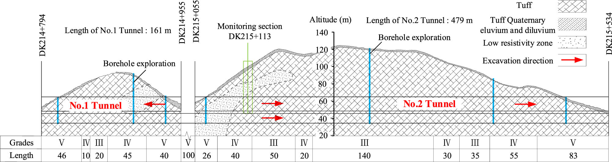
The geological diagram of prototype tunnels (unit: m).

Rock mass of prototype tunnels: (a) grade III; (b) grade IV; and (c) grades V.
3 Numerical analysis of the optimization of construction schemes
3.1 Construction schemes
Considering extremely harsh geological conditions, the double-side drift (D-SD) method and composite double-side drift (CD-SD) method are chosen as the basis of the optimization design of grade Ⅴ rocks. In contrast, the D-SD method, the central cross diagram (CRD) method, the three-bench (T-B) method, and the UB-CD method are chosen as the basis for grades IV and III rocks [19,28].
As shown in Figure 4, eight construction schemes, namely from A1 to A8, are optimized for the tunneling in grade V rocks, in which schemes A1−A4 and A5−A8 are based on the D-SD and CD-SD methods, respectively. Furthermore, twelve construction schemes are proposed for shallow super-large span tunnels in grades IV and III rocks, namely, S1–S6, in which schemes S1 and S2 refer to the D-SD method; scheme S3 refer to the CRD method; schemes S4 and S5 refer to the T-B method, and scheme S6 refers to the UB-CD method.

Optimized schemes of FDM analysis: (a) grade V rocks; (b) grades III and IV rocks. Note: the number represents the excavation sequence.
3.2 Finite difference method analysis
3.2.1 Numerical model
The construction model for the super-large span high-speed railway tunnel is plotted in Figure 5, taking grades V rocks as an example for illustration. The distance between the model bottom and invert is 75 m, and the left and right sides are 65 m away from the tunnel to eliminate the boundary effect. The mechanical response of grades III and IV rock mass is assumed to follow theM-C criterion, and the linear elastic model imitates the primary support. Considering the weak grade V rock mass exhibits obvious rheological characteristics, the elastic–plastic model is difficult to reflect the stress characteristics of the support structure. Therefore, the BK-MC rheological model is selected to simulate the mechanical properties of the grade V rock mass. The BK-MC rheological model is composed of B-K and M-C bodies in series, as shown in Figure 6. The total deviator strain rate of BK and MC model is:
where

Optimization numerical model: (a) overall model, (b) tunnel cross section, and (c) optimized schemes.

BK-MC rheological model.
The three-dimensional stress increment form of the BK model is as follows:
The deviator strain rate of the M-C model is:
where
where
The differential form of the spherical stress is:
where K denotes the Bulk modulus;
The BK-MC rheological model is written by fish language in FLAC3D and C++, and compiled into Dll dynamic-link library for use.
The Beam and Pile elements are conducted to simulate the advance pipe and the anchor, respectively. The normal displacement of four sides is fixed, the normal and tangential displacements of the model bottom are fixed, and the model top is the free surface [29]. The excavation of the tunnel is achieved with the model null command, and the footage for the grades V, IV, and III rocks is 1.6, 2, and 2 m; and the bench length of the grades V, IV, and III rocks in each drift are 9.6, 12, and 12 m, respectively.
3.2.2 Numerical parameters
Table 2 summarizes the physical and mechanical parameters of grades III and IV rock mass, which are delivered with the field investigation, laboratory tests, Hoek-Brown criteria fitting, and a significant number of trials [30,31,32], as plotted in Figure 7. The rheology parameters of BK-MC model are inverted by the particle swarm optimization annealing algorithm, as shown in Table 3. The calculation parameters of the steel arch are derived by the equivalent modulus method. The parameters of anchors, pipe shed, and advanced conduit are obtained by laboratory and field tests, as listed in Table 4.
Calculation parameters of grades III and IV rock mass
| Number | Rock grades | σ ci (MPa) | E i (GPa) | c m (kPa) | φ m (°) | ν | γ (kN m−3) |
|---|---|---|---|---|---|---|---|
| 1–1 | IV | 25.8 | 0.65 | 184 | 37 | 0.37 | 24 |
| 1–2 | IV | 25.8 | 1.01 | 223 | 31 | 0.33 | 24 |
| 1–3 | IV | 60.9 | 1.21 | 266 | 43 | 0.3 | 24 |
| 1–4 | IV | 60.9 | 2.28 | 380 | 47 | 0.26 | 24 |
| 1–5 | III | 60.9 | 3.54 | 490 | 52 | 0.26 | 25 |

Parameters acquisition of rock mass.
Mechanical parameters of BK-MC model
| E i (GPa) | ν | c m (kPa) | φ m (°) | γ (kN m−3) | |
|---|---|---|---|---|---|
| M-C parameters | |||||
| Value | 0.41 | 0.32 | 0.07 | 29 | 22 |
| B-K parameters | |||||
| Value | 0.52 | 0.28 | 0.14 | 37 | 22 |
Calculation parameters of support structures
| Rock grade | Type | h (cm) | E m (GPa) | ν | γ (kN m−3) |
|---|---|---|---|---|---|
| Ⅴ | Primary support | 50 | 27.25 | 0.24 | 25 |
| Temporary support | 30 | 22.64 | 0.24 | 25 | |
| Ⅲ, Ⅳ | Primary support | 40 | 26.33 | 0.25 | 0.25 |
| Secondary lining | 60 | 33.5 | 0.24 | 0.24 | |
| Temporary support | 30 | 22.51 | 0.25 | 0.25 |
Note: σ ci represents the uniaxial compressive strength of rocks; E i denotes the elastic modulus of rock mass; E m is the elastic modulus of support structures; c m represents the cohesion of rock mass; φ m denotes the internal friction angle of rock mass; ν represents the ratio of Poisson; γ is the unit weight; h represents the thickness of primary support.
3.2.3 Measuring points
Given the massive size of the tunnel, 27 measuring points are arranged in the monitoring system, as shown in Figure 8. Points L1, L2, …, and R8, vault, and inverted arch (i.e., black rectangle mark) are the monitoring points for rock stress, rock deformation, and internal force. Points A, B, and C (i.e., blue diamond marks) are the vertical settlement points, and the horizontal convergence measuring points (i.e., red circle marks) are points SL1, SL2, …, and SL8, respectively.

Monitoring system diagram of the FDM model.
3.3 Results and discussion of the numerical analysis
3.3.1 Rock deformation analysis
3.3.1.1 Grade V rock mass
The vault settlement curves with the construction process for the shallow super-large span tunnel are plotted in Figure 9, and the final rock deformations are listed in Table 4. First, when the shallow super-large span tunnel adopts schemes A2 and A8, the sharp increases of the vault settlement are observed in the excavation of core soils (i.e., step-③ of scheme A2 and steps-③④⑤⑥ of scheme A8) and finally lead to the maximum settlement of −75.8 and −82.2 mm, much higher than other schemes. Then, when the CD-SD method (i.e., schemes A5–A8) was employed, the vault settlement of the scheme that the upper half tunnel has been excavated in two parts (i.e., scheme A5) is much larger than that of three or four parts (i.e., schemes A6 and A7). The more pilot tunnels in the upper half section of shallow super-large span tunnel are, the minor rock deformation in grade V rocks is. Besides, when the D-SD method was implemented in super-large span tunnels, the vertical settlement of scheme A4 was slightly larger than that of schemes A1 and A3. The main reason is that the width of the rock column (i.e., parts ⑦, ⑧, and ⑨) has been shortened in scheme A4, resulting in a large rock deformation before the excavation. Also, the vault settlement of the tunnels with scheme A3 is 43.5 mm, 10–15 mm larger than that of the CD-DS method (i.e., schemes A5–A8). It can be concluded that the area of the side pilot tunnel also substantially affects the rock deformation for super-large span tunnels.

Vertical settlement of optimized models: (a) schemes A1–A4 and (b) schemes A5–A8.
From Table 5, the vault settlements of the D-SD method (i.e., schemes A1–A4) are higher than those of the CD-SD method (i.e., schemes A5–A8), while horizontal convergences of the D-SD method are lower than that of the CD-SD method. Scheme A1 exhibits the best control effect on horizontal deformation, followed by Schemes A3 and A4. Based on the above analysis, schemes A1, A3, A4, A6, and A7 are recommended for the construction of super-large span tunnels when the rock deformations are a critical control factor; scheme A1 with the most significant working space, however, could be considered first when rock deformations are within the safety threshold.
Rock deformations (unit: mm)
| Construction schemes | A1 | A2 | A3 | A4 | A5 | A6 | A7 | A8 | |
|---|---|---|---|---|---|---|---|---|---|
| Vault settlement A | −48.6 | −75.8 | −43.5 | −45.8 | −41.7 | −33.8 | −37.2 | −82.2 | |
| Horizontal convergence | SL1–SL4 | 3.7 | 5.02 | 3.21 | 4.57 | 10.52 | 10.2 | 9.54 | 12.44 |
| SL5–SL8 | 0.43 | 0.43 | 2.51 | 3.18 | 3.64 | 3.64 | 4.15 | 3.98 | |
3.3.1.2 Grade III and IV rock mass
The curves of vertical settlements and horizontal convergences with excavation footages are plotted in Figure 10, choosing tunnels in grade IV rocks (i.e., No 1–1) as examples for analysis. In general, rocks’ vertical settlement and horizontal convergence exhibit a negative relationship with the excavation distance; the deformations increase with the construction process. Meantime, rock deformations are almost the same before the excavation face arrives, while present enormous differences after it arrives. In addition, the slopes of settlement curves derive immense changes when excavating the up-bench of rock columns (i.e., step-⑤ of scheme S1, step-③ of scheme S2, steps-① and ② of scheme S3, and step-① of scheme S5), which suggest that the construction disturbances of the upper benches of core soils are much higher than other parts. The excavations of the middle- and lower benches have less effect on vault settlements. In summary, excavating upper benches for the rock column is the most critical construction step for shallow super-large span tunnels; thereby, strict monitoring management should be carried out during the construction.

Rock deformation of numerical model: (a) vertical settlement; (b) horizontal convergence.
The peak values of the vertical settlement and horizontal convergence of super-large span tunnels are summarized in Table 6. Overall, scheme S4 (i.e., the T-B step with the side pilot tunnel excavated first) has the largest vertical settlement for the shallow super-large tunnel, followed by scheme S5 (i.e., the T-B step, with the middle pilot tunnel excavated first), scheme S2 (i.e., optimized D-SD method), scheme S6 (i.e., UB-CD method), scheme S1 (i.e., D-SD method), and scheme S3 (i.e., CRD method). First, the shallow super-large span tunnel employing scheme S3 presents minor vault settlements, 37.3 mm, which reveals that fewer excavation steps of the CRD method may lead to fewer rock disturbances. Besides, the T-B method (i.e., schemes S4 and S5) in shallow super-large span tunnels has a limited control effect on the vault settlement; peak values of schemes S4 and S5 are 44.8 and 41.8 mm, respectively, with a rise of 15.8 and 9.8% compared with scheme S3. Furthermore, the horizontal convergences of the arch foot (i.e., SL1–SL4) and the wall waist (i.e., SL5–SL8) are 5.52–9.64 and 6.21–10.59 mm, respectively, which display the minor difference concerning the super-large tunnel size. In summary, the excavation sequence of the core-soil of shallow super-large span tunnels in grades III and IV rocks, however, displays a limited optimized effect on rock deformations, which are much different from grades V rocks. Also, the construction method, area, and sequence of pilot tunnels on the construction response of super-large span tunnel vary with rock mass properties. The higher the grade of the surrounding rock, the smaller the optimized effect of construction methods on rock stability.
Final rock deformation of schemes S1–S6 (unit: mm)
| Deformation | Scheme | S1 | S2 | S3 | S4 | S5 | S6 |
|---|---|---|---|---|---|---|---|
| Vault settlement | A | −25.08 | −29.16 | −30.22 | −33.93 | −33.84 | −34.03 |
| B | −38.6 | −41.6 | −37.7 | −44.8 | −43.8 | −40.9 | |
| C | −22.92 | −30.37 | −31.74 | −34.51 | −34.18 | −34.48 | |
| Horizontal convergence | SL1–SL4 | 6.27 | 6.21 | 8.79 | 6.54 | 8.12 | 10.59 |
| SL5–SL8 | 8.03 | 9.64 | 5.52 | 6.64 | 7.42 | 6.4 |
3.3.2 Internal force of primary support
3.3.2.1 Grade III and IV rock mass
The axial force curves at points vault and left arch foot (i.e., point L4) of the primary support for super-large span tunnels are depicted in Figure 11, taking grade IV rocks as instances for analysis [33]. In the case of the D-SD method (schemes S1 and S2), the upper bench of the side pilot tunnel (steps ① ②), as well as the upper bench of rock columns (step ⑤ of S1 and step ③ of S2) play a severe effect on the axial force of the left arch foot. For example, when the T-B methods (i.e., schemes S4 and S5) and the UB-CD method (i.e., scheme S6) are used for shallow super-large span tunnels, the axial force of the left arch foot increases continuously with the excavation of the upper benches, then decreases slowly, and finally turns to stable in the excavation stage of lower benches. Also, the axial force of primary support presents a similar development law among these six schemes. The upper benches of the tunnel section exhibit a vital influence, while the excavation of the lower benches has little impact on the internal force of the primary support.

Curves of the axial force: (a) point L4 and (b) point vault.
The internal forces of the primary support for shallow super-large span tunnels are plotted in Figure 12, choosing IV rocks as an example for the analysis. The six schemes’ axial force and bending moment perform similar distribution characteristics. For example, the axial forces of sidewalls (i.e., points L5 and L6) and arch-feet (i.e., points L2, L3, and L4) are much larger than those of the inverted arch and vaults; the bending moment of points L2, L4, L6, L8, R2, R4, R6, and R8 reaches the maximum, while the minimums are observed at points vault, L3, L7, and inverted arch. Besides, the peak axial forces of the primary structure have been observed when scheme S4 (i.e., the T-B method) is adopted, followed by scheme S5 (i.e., the T-B method) and scheme S3 (i.e., the CRD method); the axial forces of other three schemes are relatively small while bending moments of those schemes at the arch are more extensive, about 30–60 kN·m. Moreover, when the T-B method (i.e., schemes S4 and S5) and the UB-CD method (S6) are adopted, the stress-release rates of weak rocks are more significant than that of other schemes, which makes full use of the bearing capacity of surrounding rocks and is conducive to improve the bearing stress state of the initial support. Furthermore, the influence of construction schemes on the bearing stress of the primary structure in grade III rock is less than that in grade IV rocks. The application of the TB method and UB-CD method (i.e., schemes S4, S4, and S6) could improve the stress state of the primary support structure.

Internal forces in grades III and IV rocks: (a) axial force; (b) bending moment; (c) safety factor.
The safety factor in Chinese codes has been employed to investigate the stability of the primary support [26], as calculated in equations (6) and (7). The more significant the safety factor, the more stable the structure. Figure 11(c) plots the safety factor of the primary support in the super-large span tunnels. The safety factors of the inverted arch and wall foot have been hidden, considering their higher value than other parts. Generally, the safety factor of primary support varies with construction schemes, but they are all greater than 1.0, indicating that tunnel structures are safe and stable. Besides, the safety factor at the arch shoulder (i.e., points L2 and R2) in each scheme is close, while exhibits much difference at the arch foot (i.e., points L4 and R4), wall waist (i.e., points L5 and R5), and wall foot (i.e., points L6 and R6). The safety factors of the arch foot and arch waist in the T-B method (i.e., schemes S4 and S5) and the UP-CD method (S6) are more prominent than in other schemes. The safety factor of the vault has a minimum safety in scheme S2 and exhibits a maximum in scheme S1.
where R c represents the ultimate compressive strength; R t presents the ultimate tensile strength; φ is the bending coefficient; α is the eccentricity coefficient of axial force; e 0 represents the eccentricity of the section.
3.3.2.2 Grade V rock mass
Figure 13 calculates the internal force of primary support in grade V rocks. The points vault, L4, R4, L5, and R5 are selected as examples for analysis. Generally, the safety factors are all larger than the safety threshold, and the primary support of the super-large span tunnel is in a safe state. When the tunnel employs scheme A4, the safety factor of the left wall waist is 1.67, with a large bending moment under the tension state. When the tunnel employs scheme A5, the left arch foot (i.e., point L4) presents the most significant axial force, with a safety factor of 1.88. When schemes A5, A6, and A7 are adopted, the compressive stress of the vault is smaller than other schemes, while the axial force of left and right arch feet (i.e., L4 and R4) is larger than that of schemes A1 and A4. Overall, the stress of most points in the primary support of schemes A5−A8 is greater than that of schemes A1–A4.

Internal force in case of grade V rocks: (a) axial force; (b) bending moment; (c) safety factor.
3.3.3 Optimized scheme of super-large span tunnels
Based on the analysis of rock deformation, rock stress, internal force, the construction condition, and construction progress, the optimized schemes for the super-large span tunnel in weak soil are listed in Table 7. Also, given the short length of the prototype tunnel, the UB-CD method has been chosen in the current study to avoid construction method conversion. Temporary and advanced support is available to ensure the stability of surrounding rocks.
Optimal schemes for shallow super-large span tunnels in weak rocks
| Rock grades | Construction method | Construction schemes |
|---|---|---|
| Ⅲ | T-B, UB-CD, CRD | S5, S6 |
| Ⅳ | T-B, CRD | S1, S3 |
| Ⅴ | D-SD/CD-SD | A1, A3 |
4 Field tests of the construction method for shallow super-large span tunnel
In the construction of the prototype No.2 tunnel, the application of the preliminary scheme needs to improve its efficiency with monthly footage of 15 m, especially in excavating the lower bench of the left, right, and middle pilot tunnels. The main reasons include (1) The effective working width is less than 7 m, which cannot meet the application requirements of large-scale machines. The construction of the low bench will lead to the stagnation of the excavation of the upper bench, and synchronous excavation cannot be achieved. (2) The removal of temporary supports seriously delayed the excavation and the supporting progress of the inverted arch. (3) Due to the installation error of the steel arch frame and the deformation of the primary support, the steel arch frame of the middle pilot tunnels cannot be smoothly connected with that of the side pilot tunnels. Thus, an 8 month field test was conducted from February 2019 to November 2019. A total of four construction schemes were employed in the prototype tunnel, and the corresponding rock deformations were monitored.
4.1 Field test cases
Four construction schemes in field tests are plotted in Figure 14, namely, E1, E2, E3, and E4. The mileages of the four schemes are DK215 + 142.2, DK215 + 162.2, DK215 + 291.8, and DK215 + 302.2, respectively. Besides, scheme E4 is located at the junction of grades IV and III rocks, while the other schemes were conducted in grades III rocks.

Construction schemes for field tests: (a) scheme E1, (b) scheme E2, (c) scheme E3, and (d) scheme E4.
4.2 Monitoring system
Figure 15(a) plots the rock deformation monitoring system of the field test, in which A, B, and C are vertical settlement measuring points, and SL1–SL8 are the horizontal convergence measuring points. The vertical settlements are measured by the displacement meter, and the installation of displacement meters is shown in Figure 15(b)–(d).

Monitoring system: (a) measuring point layout; (b) displacement meters; (c) site photographs; (d) meter installation diagram.
4.3 Analysis of onsite results
Figure 16 plots the rock deformation results of field tests in the prototype tunnel. The horizontal convergence presents a complex character and varies with the construction schemes; this is because measuring points of horizontal convergence (i.e., points SL1, SL2, SL3, …, and SL8) have been arranged at temporary supports, which are sensitive to the construction disturbances. However, the lines SL1–SL4 (i.e., arch foot) and SL5–SL8 (i.e., wall waist) of four schemes exhibit a stable trend after excavating the upper bench of middle pilot tunnels, and the final values are less than 6 mm.

Deformation curves of field tests: (a) DK215 + 142.2 (scheme E1), (b) DK215 + 162.2 (scheme E2), (c) DK215 + 291.8 (scheme E3), and (d) DK215 + 302.2 (scheme E4).
From vertical settlements in Figure 16, the excavation of the upper bench for the left, right, and middle pilot tunnels are the three main stages of rock deformation. The vertical deformation accumulatively increases and tends to be stable within the first 10–30 days. In scheme E1, the excavation of the upper parts of the middle pilot tunnel lags, and the rock deformation sustains a long time, eventually leading to excessive settlements, 7–10 mm higher than in other schemes. The deformation of schemes E2, E3, and E4 presents a similar pattern, first tends to be stable after excavating the left and right pilot tunnels and then increases sharply after excavating the upper bench of middle rock columns.
As shown in Table 8, the horizontal convergence of SL1–SL4 and that of SL5–SL8 are 2.8–5.9 mm and −0.2–5.9 mm, respectively; the minimum vertical settlements of points A, B, and C are 8.7, 9.87, and 10.7 mm, respectively. Generally, scheme E4 has presented the most excellent control effect on rock deformation, followed by schemes E3, E2, and E1. Although the prototype tunnel has a super-large span of 26.3 m, the deformation value of the prototype tunnel has the same scale compared with the deformation value of the conventional size tunnel in grades III and IV rocks. The scheme presents a limited effect on the rock deformation for the super-large span tunnel, which presents a good agreement with the numerical simulation. In summary, the rock deformation and field feedback indicate that scheme E4 promotes the low bench’s excavation and support efficiency, accelerates the primary support’s closed-loop speed, and thus improves the construction speed of the secondary lining. Scheme E4 is the most reasonable optimization scheme, and it is recommended for the construction of the prototype tunnel.
Final rock deformations of field test
| Construction scheme | Rock grades | Horizontal convergence (mm) | Vertical settlement (mm) | |||
|---|---|---|---|---|---|---|
| SL1–SL4 | SL5–SL8 | A | B | C | ||
| E1 | IV | 5.7 | 5.9 | 22.6 | 16.1 | 17.1 |
| E2 | III | 5.9 | 3.9 | 14.7 | 19.2 | 12.6 |
| E3 | III | 3.6 | 3.2 | 14.7 | 16.2 | — |
| E4 | III | 2.8 | −0.2 | 8.7 | 9.78 | 10.7 |
5 The suggested construction method selection chart for the super-large tunnel
By combining numerous cases analyses with numerical simulation and field tests in the present study, a suggested construction method selection chart has been proposed for the super-large span tunnel with a span between 18 and 34 m, as shown in Figure 17, in which the abscissa is the modified [BQ], and the ordinate is the excavation span. According to Chinese codes, the [BQ] of grades III, IV, and V rocks are 351–450, 251–350, and ≤250, respectively [26]. It should be noted that the excavation sequence and area of pilot tunnels shall be determined by referring to the mechanical configuration, rock strength, tunnel covering, and other conditions.

Suggested construction method selection chart of super-large span tunnels.
6 Conclusion
This article aims to explore the optimized construction schemes of shallow super-large span four-line high-speed railway tunnel in weak tuff rocks. A total of 20 construction schemes are optimized through the FDM analysis, and an 8 -month field test and 3-year investigations are conducted in the prototype tunnel. The following conclusions can be drawn:
Excavating the upper bench of middle pilot tunnels is the most significant step for super-large span tunnels in weak rocks. The rock deformation could be well controlled by excavating the side pilot tunnel first and then the middle rock column in weak rocks; the span rate of the side pilot tunnel to the middle pilot tunnel should also be considered in the optimized design of construction schemes.
The influence of the construction method, area, and excavation sequence of pilot tunnels of construction scheme on the construction response of super-large span tunnel varies with rock mass properties. The higher the property of the surrounding rock, the smaller the influence of construction methods on the rock’s stability. The D-SD, CRD, and T-B methods could be employed in grade IV rocks; the T-B and upper-bench central diagram methods are suggested in grade V rocks.
The field test shows that the construction efficiency could be enhanced by optimizing the excavation sequence of the upper bench, the removal mode of temporary supports, and the pilot tunnel quality of the lower bench. Field tests show that scheme E4 is the most reasonable construction method for the prototype tunnels.
The suggested construction method selection chart for shallow super-large span tunnels with a span range of 17–34 m has been proposed, which could provide a scientific reference for choosing the construction method of the large span tunnels.
-
Funding information: This work is supported by the National Natural Science Foundation of China (51678033) and the open foundation (CL19048530) of China Railway Major Bridge Engineering Group Co., LTD.
-
Author contributions: Conceptualization, X.L., S.H., J.H, and J.M.; methodology, S.H. and J.M.; investigation, L.X. and J.M.; data curation, J.M.; writing – original draft preparation, J.M. and X.L.; writing – review and editing, J.M. and X.L.; project administration, J.M. and S.H.; funding acquisition, S.H. and X.L.
-
Conflict of interest: The authors declared that they have no conflicts of interest in this work.
-
Ethical approval: The conducted research is not related to either human or animal use.
-
Data availability statement: All data generated or analyzed during this study are included in this published article.
References
[1] Zhang J-R, Wu J, Yan C-W, Gou X-M, Ye L, Feng J-M. Construction technology of super-large section of highway tunnels with four or more lanes in China. Zhongguo Gonglu Xuebao/China J Highw Transp. 2020;33(1):14–31.10.1155/2020/6836492Search in Google Scholar
[2] Hong K-R, Feng H-H. Development trends and views of highway tunnels in china over the past decade. Zhongguo Gonglu Xuebao/China J Highw Transp. 2020;33(12):62–76.Search in Google Scholar
[3] Shiroma H, Ito T, Seki S. Study of tunnel support reduction for large scale tunnels. ISRM International Symposium/3rd Asian Rock Mechanics Symposium (ARMS). Kyoto, JAPAN; 2004. p. 605–10.Search in Google Scholar
[4] Noh S, Lee SP. A case study of minimizing construction timein long and large twin tube tunnel. Tunn Undergr Space. 2005;15(3):89–98.Search in Google Scholar
[5] Maghous S, Winiawer JEB, Pasa Dutra VF. Stability analysis of tunnels driven in jointed rocks by means of a homogenized limit analysis approach. Int J Numer Anal Methods Geomech. 2014;38(18):2009–32.10.1002/nag.2302Search in Google Scholar
[6] Liu X, He S, Wang D, Zhang J, Yao W. Mechanical characteristics of primary support system at construction phase in shallow-buried super-large-span four-line high-speed railway tunnel. Zhongguo Tiedao Kexue/China Railw Sci. 2021;42(6):90–102.Search in Google Scholar
[7] Li X, He C, Geng P, Ding J. Construction schemes and supports mechanical characteristics of shallow embedded large-section tunnel. Zhongnan Daxue Xuebao (Ziran Kexue Ban)/Journal Cent South Univ (Sci Technol). 2015;46(9):3385–95.Search in Google Scholar
[8] Ma E, Lai J, Xu S, Shi X, Zhang J, Zhong Y. Failure analysis and treatments of a loess tunnel being constructed in ground fissure area. Eng Fail Anal. 2022;134:106034.10.1016/j.engfailanal.2022.106034Search in Google Scholar
[9] Barton N. A Tragic and Unpredictable Station Cavern Collapse During Construction of a Metro, Despite Extensive Drilling Investigations Paper No.373, International Society for Rock Mechanics and Rock Engineering; 2009.Search in Google Scholar
[10] Hou F, Sun K, Zhao R, Zhou H, Xu W, Zhou Z, et al. Applicability study on construction method of super-large section neighborhood tunnel. Tumu Gongcheng Xuebao/China Civ Eng J. 2017;50:111–6.Search in Google Scholar
[11] Rast M, Galli A, Ruh JB, Guillong M, Madonna C. Geology along the Bedretto tunnel: Kinematic and geochronological constraints on the evolution of the Gotthard Massif (Central Alps). Swiss J Geosci. 2022;115(1):8.10.1186/s00015-022-00409-wSearch in Google Scholar
[12] Zheng G, Wang R, Lei H, Zhang T, Li H. A novel sequential excavation method for constructing large-cross-section tunnels in soft ground: Practice and theory. Tunn Undergr Space Technol. 2022;128:104626.10.1016/j.tust.2022.104626Search in Google Scholar
[13] Wang HN, Utili S, Jiang MJ, He P. Analytical Solutions for Tunnels of Elliptical Cross-Section in Rheological Rock Accounting for Sequential Excavation. Rock Mech Rock Eng. 2015;48(5):1997–2029.10.1007/s00603-014-0685-7Search in Google Scholar
[14] Hou F, Luo Y, Jiang Q, Chen J, Li T, Dong F. Analysis on construction deformation and supporting structure of two-step and three-section excavation method for super larger span highway tunnel. Civ Eng J. 2020;29(1):110–23.10.14311/CEJ.2020.01.0010Search in Google Scholar
[15] Luo J, Zhang D, Fang Q, Li A, Liu D, Yu L, et al. Combined support mechanism of pretensioned rock bolt and anchor cable for super-large-span tunnel. Zhongguo Tiedao Kexue/China Railw Sci. 2020;41(5):71–82.Search in Google Scholar
[16] Luo Y-B, Shi Z, Chen J-X, Liu W-W, Chen L-J, Li Y, et al. Mechanical calculation model and research on construction mechanical behavior of middle diaphragm in upper bench CD method for super-large span tunnel CD. Zhongguo Gonglu Xuebao/China J Highw Transp. 2020;33(12):235–48.10.1155/2020/8887040Search in Google Scholar
[17] Zhang D-M, Pang J, Ren H, Han L. Observed deformation behavior of Gongbei Tunnel of Hong Kong-Zhuhai-Macao Bridge during construction. Yantu Gongcheng Xuebao/Chin J Geotech Eng. 2020;42(9):1632–41.Search in Google Scholar
[18] Tan Z, Zhou Z, Kong H, Zhao B, Zhao J. Single excavation face method for super-large-span bifurcated tunnels. Proc Inst Civ Eng: Geotech Eng. , 2021;174(4):406–18.10.1680/jgeen.20.00222Search in Google Scholar
[19] Luo Y, Dong F, Wang C, Chen J, Zhu T, Zhang L, et al. A surrounding rock pressure calculation method for super-large-span highway tunnels considering sequential excavation. Yanshilixue Yu Gongcheng Xuebao/Chin J Rock Mech Eng. 2022;41(8):1637–46.Search in Google Scholar
[20] Luo Y, Wu Y, Chen J, Dong F, Liu W, Chen L, et al. Back-calculation method of rock mass pressure in a shallow-buried super large-span tunnel using upper-bench CD method. KSCE J Civ Eng. 2022;26(1):433–47.10.1007/s12205-021-0312-6Search in Google Scholar
[21] Zhou S, Zhou Z, Liu H, Li L, Li J, Shang C, et al. Mechanical response of supporting structure of closely spaced super large span twin tunnels. Geotech Geol Eng. 2022;40(10):4879–94.10.1007/s10706-022-02188-5Search in Google Scholar
[22] Hoek E. Big tunnels in bad rock. J Geotech Geoenviron Eng. 2001;127(9):726–40.10.1061/(ASCE)1090-0241(2001)127:9(726)Search in Google Scholar
[23] Russo G. An update of the “multiple graph” approach for the preliminary assessment of the excavation behaviour in rock tunnelling. Tunn Undergr Space Technol. 2014;41:74–81.10.1016/j.tust.2013.11.006Search in Google Scholar
[24] Daraei A, Zare S. A new multi-graph approach for selecting the sequential excavation method of civil tunnels. Tunn Undergr Space Technol. 2019;91:102999.10.1016/j.tust.2019.102999Search in Google Scholar
[25] MOHURD. Code for design of concrete structures. Beijing: China Construction Industry Press; 2011.Search in Google Scholar
[26] R.T.S.o.t.P.s.R.o. China. Code for design of railway tunnel: TB 10003—2016. Beijing: China Railway Publishing House; 2017.Search in Google Scholar
[27] M.o.H.a.U.-R.D.o.t.P.s.R.o. China. GBT50218-2014 Standard for engineering classification of rock mass. Beijing: China Planning Press; 2014.Search in Google Scholar
[28] Liu C, Li S-C, Zhou Z-Q, Li L-P, Wang K, Hou F-J, et al. Model test on mechanical characteristics of surrounding rock during construction process of super-large section tunnel in complex strata. Yantu Lixue/Rock Soil Mech. 2018;39(9):3495–505.Search in Google Scholar
[29] Sharifzadeh M, Kolivand F, Ghorbani M, Yasrobi S. Design of sequential excavation method for large span urban tunnels in soft ground – Niayesh tunnel. Tunn Undergr Space Technol Incorporating Trenchless Technol Res. 2013;35:178–88.10.1016/j.tust.2013.01.002Search in Google Scholar
[30] Sonmez H, Ulusay R. Modifications to the geological strength index (GSI) and their applicability to stability of slopes. Int J Rock Mech Min Sci. 1999;36(6):743–60.10.1016/S0148-9062(99)00043-1Search in Google Scholar
[31] Hoek E, Brown ET. Practical estimates of rock mass strength. Int J Rock Mech Min Sci. 1997;34(8):1165–86.10.1016/S1365-1609(97)80069-XSearch in Google Scholar
[32] Cai M, Kaiser PK, Uno H, Tasaka Y, Minami M. Estimation of rock mass deformation modulus and strength of jointed hard rock masses using the GSI system. Int J Rock Mech Min Sci. 2004;41(1):3–19.10.1016/S1365-1609(03)00025-XSearch in Google Scholar
[33] Cui GY, Ma JF. Combination of lining strengthening and buffer layers for soft and hard rock tunnels junction subjected to seismic waves. Geomat Nat Hazards Risk. 2021;12(1):522–39.10.1080/19475705.2021.1886184Search in Google Scholar
© 2023 the author(s), published by De Gruyter
This work is licensed under the Creative Commons Attribution 4.0 International License.
Articles in the same Issue
- Research Articles
- Vibrational wave scattering in disordered ultra-thin film with integrated nanostructures
- Optimization of lead-free CsSnI3-based perovskite solar cell structure
- Determination of the velocity of seismic waves for the location of seismic station of Zatriq, Kosovo
- Seismic hazard analysis by neo-deterministic seismic hazard analysis approach (NDSHA) for Kosovo
- Ultimate strength of hyper-ellipse flanged-perforated plates under uniaxial compression loading
- Development of an adaptive coaxial concrete rheometer and rheological characterisation of fresh concrete
- Synthesis and characterization of a new complex based on antibiotic: Zirconium complex
- Exergy–energy analysis for a feasibility trigeneration system at Kocaeli University Umuttepe Campus
- Transient particle tracking microrheology of plasma coagulation via the intrinsic pathway
- Analysis of complex fluid discharge from consumer dispensing bottles using rheology and flow visualization
- A method of safety monitoring and measurement of overall frost heaving pressure of tunnel in seasonal frozen area
- Application of isolation technology in shallow super-large comprehensive pipe galleries in seismically vulnerable areas with weak soils
- Application of the ramp test from a closed cavity rheometer to obtain the steady-state shear viscosity η(γ̇)
- Research on large deformation control technology of highly weathered carbonaceous slate tunnel
- Tailoring a symmetry for material properties of tellurite glasses through tungsten(vi) oxide addition: Mechanical properties and gamma-ray transmissions properties
- An experimental investigation into the radiation-shielding performance of newly developed polyester containing recycled waste marble and bismuth oxide
- A study on the fractal and permeability characteristics of coal-based porous graphite for filtration and impregnation
- Creep behavior of layered salt rock under triaxial loading and unloading cycles
- Research and optimization of tunnel construction scheme for super-large span high-speed railway tunnel in poor tuff strata
- Elongational flow mixing: A novel innovative approach to elaborate high-performance SBR-based elastomer compounds
- The ductility performance of concrete using glass fiber mesh in beam specimens
- Thickened fluids classification based on the rheological and tribological characteristics
- Strength characteristics and damage constitutive model of sandstone under hydro-mechanical coupling
- Experimental study of uniaxial compressive mechanical properties of rough jointed rock masses based on 3D printing
- Study on stress distribution and extrusion load threshold of compressed filled rock joints
- Special Issue on Rheological Behavior and Engineering Stability of Rock Mass - Part II
- Seismic response and damage mechanism of tunnel lining in sensitive environment of soft rock stratum
- Correlation analysis of physical and mechanical parameters of inland fluvial-lacustrine soft soil based on different survey techniques
- An effective method for real-time estimation of slope stability with numerical back analysis based on particle swarm optimization
- An efficient method for computing slope reliability calculation based on rigorous limit equilibrium
- Mechanical behavior of a new similar material for weathered limestone in karst area: An experimental investigation
- Semi-analytical method for solving stresses in slope under general loading conditions
- Study on the risk of seepage field of Qiantang River underground space excavated in water-rich rheological rock area
- Numerical analysis of the impact of excavation for undercrossing Yellow River tunnel on adjacent bridge foundations
- Deformation rules of deep foundation pit of a subway station in Lanzhou collapsible loess stratum
- Development of fiber compound foaming agent and experimental study on application performance of foamed lightweight soil
- Monitoring and numerical simulation analysis of a pit-in-pit excavation of the first branch line of Lanzhou Metro
- CT measurement of damage characteristics of meso-structure of freeze-thawed granite in cold regions and preliminary exploration of its mechanical behavior during a single freeze-thaw process