Application of isolation technology in shallow super-large comprehensive pipe galleries in seismically vulnerable areas with weak soils
-
Jianfei Ma
 ,
Guangyao Cui
,
Guangyao Cui
 and
Xiabing Liu
and
Xiabing Liu

Abstract
Shallow urban tunnels with super-large sections in weak soils may experience much more devastating seismic hazards than conventionally deep tunnels in seismically vulnerable areas. This study investigates the seismic response and isolation technology for the largest comprehensive urban pipe gallery in the Xiong’an New Area, Hebei Province, China, using seismic simulation. First, the engineering background, static-seismic model, dynamic motions, and measuring points of the numerical simulation are introduced. Then, using the finite difference method to explore seismic behaviors of the super-large comprehensive urban pipe gallery under strong earthquake excitations are explored. The indexes including the deformation, the stress, the internal force, and the safety factor of segments are analyzed. Meanwhile, the aseismic effects of three proposed isolation schemes (namely, the cushion scheme, the partial buffer layer, and the integral buffer layer), which are proposed to be employed in the super-large comprehensive urban pipe gallery, are explored comparatively. The result shows that the integral buffer layer presents the most dramatic seismic isolation effect (97.85%), followed by the partial buffer layer (22.58%), and the cushion (15.07%). The integral buffer layer scheme is recommended to be employed in the seismic design for the present super-large pipe gallery. These conclusions can give scientific guidance for the seismic design of the super-large urban tunnels.
1 Introduction
The rapid development of the infrastructure has led to a growing demand for large-section and comprehensive urban tunnels that integrate drainage pipelines, natural gas pipelines, energy, and transportation caves into a large cross-section structure [1]. Comprehensive urban tunnels are environmentally friendly and have high space utilization [2], but their large cross-section and multifunctionality can increase the risk of severe damage during earthquakes, resulting in economic and societal losses. Additionally, these comprehensive urban tunnels are often located in the downtown area, making seismic maintenance extremely difficult [3]. As a result, there is considerable interest in developing seismic response and seismic technology for super-large urban tunnels.
It has long been believed that tunnels suffer less seismic excitation because they are surrounded by soils or rocks, but severe hazards have been observed in recent earthquake events, including rock falling, lining uplifting, soil liquefaction, structure cracking, as well as collapsing [4,5]. The seismic reviews have indicated that the urban tunnel, with weak geological conditions and shallow depth, may suffer much more serious catastrophes in the seismically vulnerable areas [6,7].
In this regard, a large number of research works have been conducted on the seismic design for shallow urban tunnels, mainly containing the dynamic behaviors and seismic resistance. In terms of the dynamic response, Wang et al. and Sun et al. explored the dynamic response of shallow-bias tunnels with asymmetric loading [8,9]. Sun et al. and Wang et al. researched the seismic responses and damage mechanisms of the portal section of the shallow buried tunnel [10,11]. An et al. optimized the seismic ground motion parameters and analyzed their correlations with seismic behaviors for the shallow-buried rectangular tunnel [12]. Other parameters such as the rock joint [13], the cross-section [14], and geological conditions [4] have also been observed.
The seismic resistance comprises the reinforcement method and shock absorption. In terms of the reinforcement method, the lining reinforcement (including the fiber-reinforced concretes, high-performance concrete, special seismic structure, etc.) and the rock strengthening (including the grouting, rock bolt, and so on) are two main fields [15]. Nevertheless, the reinforcement method cannot have an ideal effect in strong seismically vulnerable zones, especially in complex geological conditions [16]. Therefore, the Japanese scholars first proposed the isolation layer, that is, employing a layer of flexible special materials, aiming to absorb or isolate the seismic excitation on the tunnel structure [17,18]. Afterward, Wang and Cui proposed the isolation model of the tunnel, and factors such as layer stiffness, input motion, and damping were evaluated [19]. Ma et al. introduced foamed concrete as the isolation material and explored its shock absorption capacity through indoor tests and finite element method [20]. To date, various isolation layers have been put forward, such as the sponge rubber sheet, foam concrete, asphalt sand, and so on, and their thickness, construction position, and interaction with other aseismic measures are explored in detail. The above studies have provided a scientific guide for the urban tunnel in seismically active zones. However, due to the relatively slow development of the super-large and extremely shallow buried tunnels, the seismic response and shock absorption for the super-large pipe are rarely investigated, let alone for the tunnel in weak soils.
Therefore, in this study, based on the largest section urban pipe gallery with a shallow buried depth in weak soils, the seismic response for the super-large urban pipe gallery is explored by the finite difference method, and the isolation scheme was explored. The seismic effect of the cushion scheme, the partial buffer layer, and the integral buffer layer were investigated by the full earthquake simulation. Various indexes such as the deformation, principal stresses, shear stress, and safety factors were analyzed in detail.
2 Research background
The research object, located in the Xiong’an New Area of the Hebei Province, China, is a comprehensive urban pipe gallery consisting of four chambers in total, namely, a gas module, an integrated module, and two power modules, as illustrated in Figure 1. This pipe gallery, with the largest section and hoisting weight at present in China, was classified as the super-large section gallery referring to the China Code [21]. Besides, this pipe gallery employs the prefabrication and hoisting scheme for the construction. The segment is C45 waterproof concrete, and the 4 m and 8 m long pipes are approximately 201 t and 402 t, respectively [22]. Geologically, the tunnel is situated in weak soils, which mainly includes clay, silty clay, and silty fine sand. The seismic-fortification intensity of the tunnel site areas is eight degree, and it increases to nine degree for some significant facilities [23]. Therefore, the nine-degree seismic intensity is employed for the super-large pipe gallery in our research.
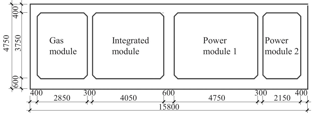
The super-large comprehensive urban pipe galley (unit: mm).
3 Full seismic model
3.1 Calculation condition
To explore the isolation technology for the super-large pipe gallery, three seismic conditions with isolation schemes and one without approach were used in the numerical simulation, as listed in Table 1. The C25 concrete and the sponge rubber plate, with a thickness of 10 cm, were chosen as the cushion and the buffer layer, respectively. And the cushion and buffer layers are set between the initial support and linings. Figure 2 plots the detailed profiles of four calculation conditions, in which the red line represents the seismic measures.
Calculation conditions
| Calculation condition | Remarks |
|---|---|
| 1 | Original tunnel |
| 2 | Tunnel with cushion |
| 3 | Tunnel with partial buffer layer |
| 4 | Tunnel with integral buffer layer |

Calculation conditions: (a) Condition 1; (b) Condition 2; (c) Condition 3; and (d) Condition 4.
3.2 Software situation
FLAC3D, developed by Itasca International Inc., is a professional geotechnical analysis software. The software employs the Lagrange fast difference method, which can calculate the deformation, stress, and stability of the rock mass under various external loads, especially in the analysis of the large deformation problem and post-peak characteristics after soil failure [24]. At present, the software has been widely used in slopes, foundation pits, tunnels, underground caverns, mining, energy, and nuclear waste village. Besides, in terms of the nonlinear dynamic calculation, FLAC can conduct the three-dimensional complete dynamic analysis, and its fully nonlinear method can follow any nonlinear constitutive model that can be specified. It can not only simulate the interference of seismic waves with different frequencies and irreversible displacement but also reproduce the propagation of shear and compression waves.
3.3 Basic assumption
It is supposed that the rock, primary support, lining, cushion layer, and buffer layer are homogeneous and isotropic materials.
The failure of the rock mass follows the Mohr–Coulomb criterion, and the linear elastic model is adopted for primary lining, secondary lining, cushion, and buffer layers.
The lateral, longitudinal, and vertical directions of the seismic motion correspond to the x-, y-, and z-axis of the numerical model, respectively.
3.4 Numerical model
The mesh is established by the professional CAE software (i.e., HyperMesh Software), and then imported into FLAC3D. Considering computer performances, working efficiency, grid control method (equation (1)), and a large number of trial calculations, the mesh for the buffer layer, cushion layer, and the mesh of the pipe gallery is 0.2–0.5 m, and the rock in blue is 0.5–1.0 m, while the mesh size of the rock in red and green is 1.0–3.0 m [25], as shown in Figure 3.
where

Calculation model of the initial stress field.
The bedrock layer is within 10 m from the bottom of the model to simulate the rigid foundation in the natural stratum. Moreover, it is indicated that there is complete contact between the surrounding rock and lining, lining and damping layer, that is, the normal and tangential displacement and stress between contact surfaces are equal.
The isolation simulation comprises the initial stress calculation and the seismic dynamic calculation. First, the normal constraint and quiet boundary are employed at the four sides and bottom in the static model, as illustrated in Figure 3. Then, the excavation and support procedures of the tunnel are performed in the numerical simulation, to seek the actual stress field in the natural condition. A vital step in the static calculation is that the displacement field is eliminated, while the stress field is not modified.
In the seismic dynamic calculation, the 2008 Wenchuan Earthquake acceleration waves, recorded by the Wolong Station, are chosen as the original dynamic loads [26]. The seismic boundary conditions are applied at the model boundary or internal nodes to simulate the external and internal dynamic loads borne by rock mass in the FLAC3D. In the present research, the seismic motions propagate upward from the bottom after filtering and baseline correction. Filtering can eliminate noise waves during the collection of seismic waves, while baseline correction can eliminate residual displacement at the end of dynamic calculations. Figure 4 plots the modified seismic waves employed in the simulation. Meanwhile, the free-field boundary is adopted to reduce or eliminate the reflection of seismic waves, as shown in Figure 5. Equations (2)–(4) give the calculation method of unbalanced force at the free-field boundary. Considering that the local damping is independent of frequency and could obtain a more accurate solution, the local damping with a coefficient of 0.157 is employed during the dynamic calculation [27].
where

Seismic motions: (a) lateral load; (b) longitudinal load; and (c) vertical load.

Seismic model: (a) front view and (b) side view.
3.5 Mechanical parameters
The physical and mechanical parameters of surrounding rocks, tunnel lining, cushion, and buffer layer were obtained from the geological survey report and laboratory results, as listed in Table 2.
Physical and material parameters
| Material | Density (kg/m3) | Elastic modulus (GPa) | Poisson’s ratio | Cohesion (MPa) | Internal friction angle (°) |
|---|---|---|---|---|---|
| Surrounding Ⅱ rock | 2,500 | 20 | 0.2 | 1.5 | 50 |
| Surrounding Ⅴ rock | 2,000 | 1.5 | 0.4 | 0.1 | 25 |
| C45 waterproof concrete | 2,500 | 33.5 | 0.2 | — | — |
| C25 Concrete | 2,200 | 25 | 0.2 | — | — |
| Buffer layer | 2,300 | 8 | 0.25 | — | — |
| Bedrock | 2,800 | 20 | 0.2 | 1.5 | 50 |
3.6 Monitoring system
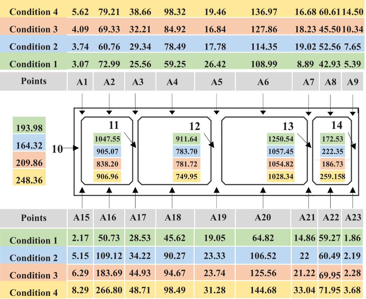
Considering the super-large size of the segment, 23 measuring points (A1–A23) were arranged at the segment surface, in which A1, A3, A5, A7, A9, A15, A17, A19, A21, and A23 are at joints, A2, A4, A6, A8, A16, A18, A20, and A22 are on the plates, A10–A14 are on the partition walls, as illustrated in Figure 6.

Measuring points.
4 Result and analysis
4.1 Lining deformation analysis
Figure 7 illustrates the deformation of the super-large pipe gallery under the nine-degree seismic motion. The deformation program presents the same characteristics in four conditions. The joint of the middle column (i.e., A19) suffers the largest deformation, while A10 at the left sidewall experiences relatively few seismically induced deformations. The utility tunnel is subject to various forces during earthquakes, including forced displacement, seismic inertial forces, and soil loads. The middle column’s deformation is the most significant due to the larger spans of the Integrated module and Power module 1. For Condition 1, the maximum and minimum deformations appear at A19 and A10, 12.15 and 10.05 mm, respectively. In Condition 2, the maximum and minimum deformation of the super-large gallery decreases to 10.56 and 9.64 mm after employing the cushion scheme. When the sponge rubber plate was partly adopted in the super-large gallery, the maximum deformation has a reduction percentage of 18.11% compared with Condition 1. Finally, the maximum and minimum deformation decreases to 7.68 and 6.38 mm when the integral buffer layer is performed. As a result, the cushion and buffer layers have decreased the seismic deformation for the super-large utility tunnel, in which the integral buffer layer presents the most dramatical seismic effect (36.79%), followed by the partial buffer layer (18.11%) and the cushion scheme (13.00%), as summarized in Table 3.

Deformation of the super-large gallery. (a) Original tunnel; (b) tunnel with the cushion; (c) tunnel with the partial buffer layer; and (d) tunnel with the integral buffer layer. (Unit: m).
Maximum segment deformation
| Calculation conditions | Seismic schemes | Maximum deformation (mm) | Reduction percentage |
|---|---|---|---|
| 1 | — | 12.15 | — |
| 2 | Cushion scheme | 10.57 | 13.00 |
| 3 | Partial buffer layer | 9.95 | 18.11 |
| 4 | Integral buffer layer | 7.68 | 36.79 |
4.2 Principal stress analysis
Figure 8 plots the maximum principal stress (i.e., the maximum component of the principal stress) of the super-large pipe gallery under the action of the strong earthquakes. Generally, the stress concentration emerges at joints of the plates and column, especially at A15, A17, A19, A21, and A23. In Condition 1, the peak value of the maximum principal stress of the super-large gallery pipe is 1.18 MPa, and it decreases to 0.83 MPa, with a decreasing percentage of 29.66% in Condition 2. When the partial buffer layer is conducted in Condition 3, the maximum decreases to 0.78 MPa, with a 33.90% decreasing percentage. Finally, when the gallery pipe was wrapped integrally with the 10 cm thick sponge rubber plate, the maximum principal stress is 0.46 MPa, which presents a 61.02% reduction with respect to Condition 1.

Maximum principal stress. (a) Original tunnel; (b) tunnel with the cushion; (c) tunnel with the partial buffer layer; and (d) tunnel with the integral buffer layer. (Unit: Pa).
Differing from the maximum principal stress, the concentration of the minimum principal stress (i.e., the minimum component of the principal stress) emerges at the roof plate (Figure 9), especially at A1, A2, A4, A6, and A8. The peak value of the minimum principal stress is 2.31 MPa in Condition 1, and it reduces to 2.19 MPa when the cushion is employed under the baseboard, with a 5.2% reduction. If the buffer layer is wrapped partially (i.e., Condition 3), the minimum principal stress decreases to 1.89 MPa, and an 18.18% decrease is observed compared with the original tunnel. In turn, the minimum principal stress decreases to 1.63 MPa, with a 29.44% reduction percentage accordingly, when employing the integral buffer layer for the super-large utility tunnel.

Minimum principal stress. (a) Original tunnel; (b) tunnel with the cushion; (c) tunnel with the partial buffer layer; and (d) tunnel with the integral buffer layer. (Unit: Pa).
Table 3 lists the principal stress and reduction in the super-large pipe gallery compared with Condition 1. As will be readily seen, the application of four isolation schemes could reduce or absorb the seismic motion, thus weakening the seismic force on the tunnel, and finally relieving the stress concentration of the tunnel segments. In terms of the principal stress, the integral buffer layer presents the dramatical isolation effect for the super-large pipe gallery, followed by the partial buffer and the cushion scheme.
4.3 Shear stress analysis
As illustrated in Figure 10, the concentration of the maximum shear stress (i.e., the maximum component of the structural shear stress after the earthquake) appears on joints and columns, especially at A12, A13, A14, A15, and A23. From Table 4, the peak shear stress reaches 1.11 MPa for the super-large pipe gallery without seismic schemes. However, it reduces to 0.90 MPa when performing the C25 concrete cushion, with a reduction of 18.49%. In Condition 3, the maximum decreases to 0.76 MPa with a reduction of 31.86%, when the partial buffer layer was adopted for the super-large pipe gallery. Besides, the peak of the shear stress presents a dramatical reduction while the integral buffer layer conducts in the seismic design, with a peak value of 0.71 MPa and a corresponding reduction of 35.78%. Moreover, the stress concentration in the original tunnel and the tunnel with cushion scheme mainly occurs at the corners of the pipe gallery, whereas in calculation Conditions 3 and 4, it appears in the middle partition walls. This is due to the buffer layer not only reducing the seismic impact on the structure but also promoting more uniform force distribution, thus reducing the occurrence of stress concentration.
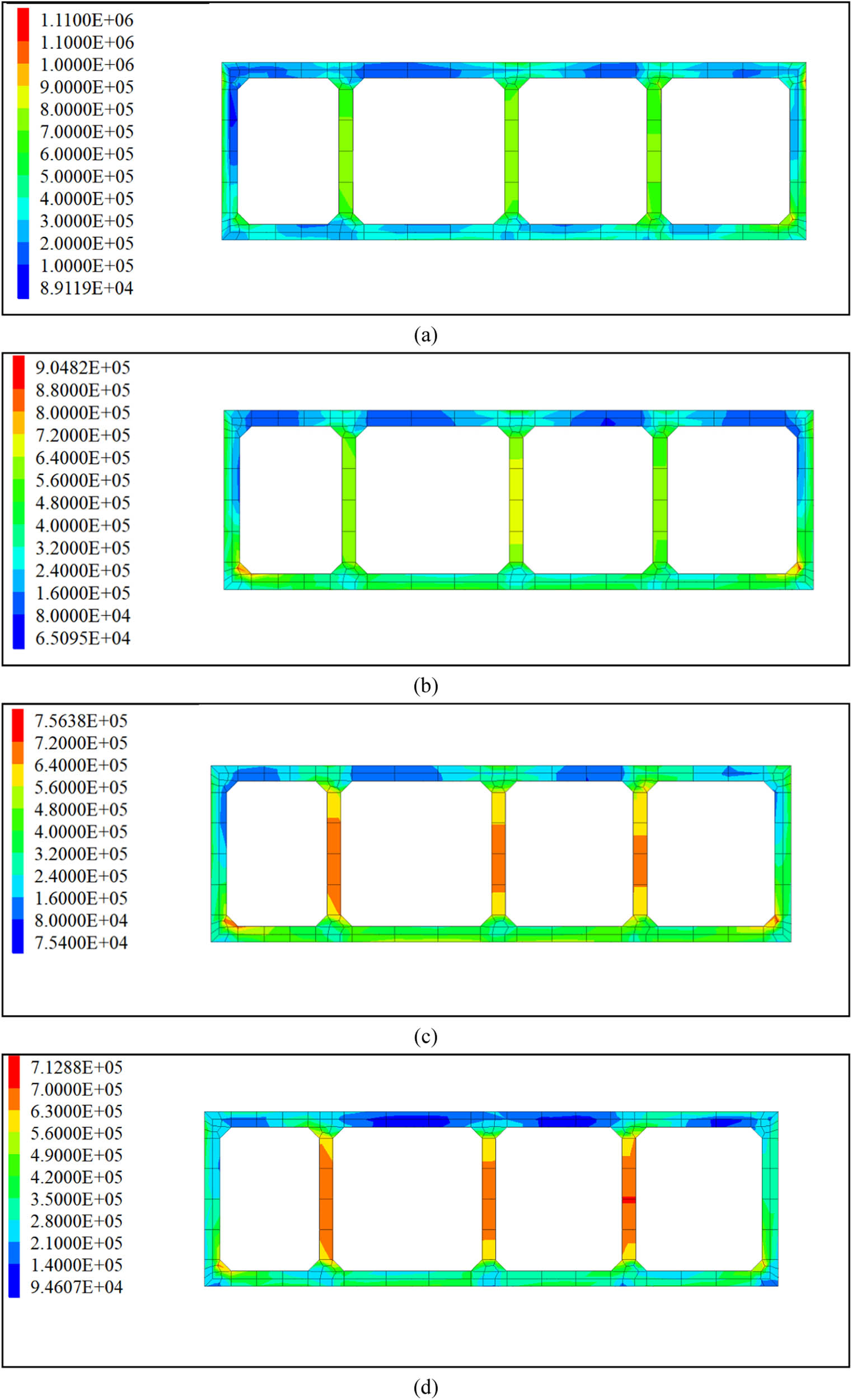
Maximum shear stress. (a) Original tunnel; (b) tunnel with the cushion; (c) tunnel with the partial buffer layer; and (d) tunnel with the integral buffer layer. (Unit: Pa).
Maximum and minimum principal stress
| Calculation conditions | Seismic schemes | Maximum principal stress (MPa) | Reduction percentage | Maximum principal stress (MPa) | Reduction percentage |
|---|---|---|---|---|---|
| 1 | — | 1.18 | — | 2.31 | — |
| 2 | Cushion scheme | 0.83 | 29.66 | 2.19 | 5.20 |
| 3 | Partial buffer layer | 0.78 | 33.90 | 1.89 | 18.18 |
| 4 | Integral buffer layer | 0.46 | 61.02 | 1.63 | 29.44 |
To sum up, same as the deformation and principal stresses, the cushion, the partial buffer layer, and the integral buffer layer minimize the seismic motion on the segments, thus decreasing the shear stress. In the aspect of the shear stress, as listed in Table 5, the integral sponge rubber plate performs the most excellent seismic isolation behaviors, followed by the partial buffer layer and the cushion scheme.
Maximum shear stress
| Calculation conditions | Seismic schemes | Maximum shear stress (MPa) | Reduction percentage |
|---|---|---|---|
| 1 | — | 1.11 | — |
| 2 | Cushion scheme | 0.90 | 18.49 |
| 3 | Partial buffer layer | 0.76 | 31.86 |
| 4 | Integral buffer layer | 0.71 | 35.78 |
4.4 Safety factor analysis
The safety factor, introduced in the China Code, was employed as the evaluation index of structural safety in seismically vulnerable areas in this study [28,29]. The safety factor is calculated by equations (5) and (6). From the history load of the safety of the A1 and A19 (Figures 11 and 12), the seismic response of different points and condition presents a huge difference. In theory, the tunnel presents a weaker seismic performance as the safety decreases. Thus, the minimum safety factors of the points for the super-large pipe gallery were summarized in Figure 13.
where K is the safety factor;
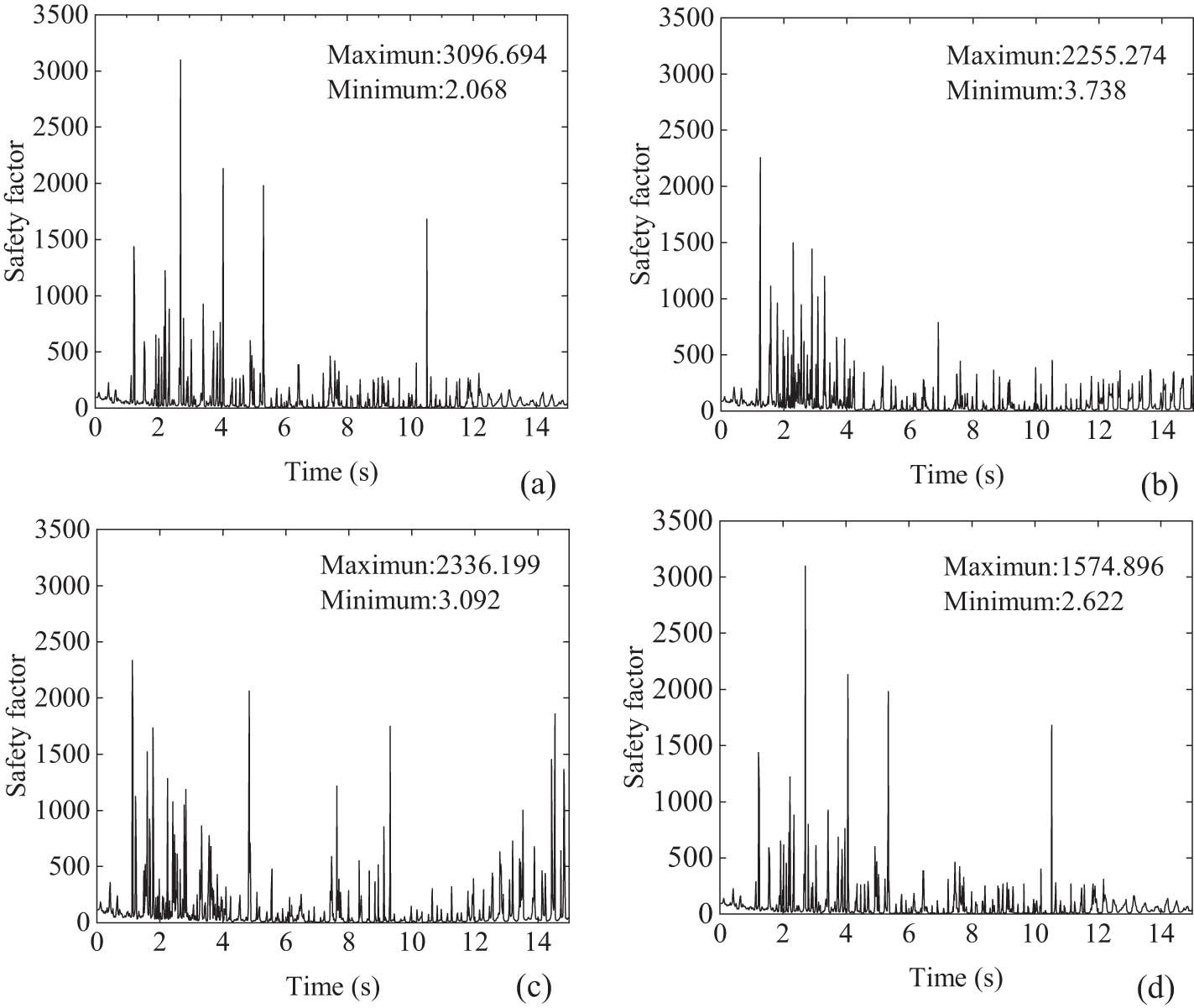
Safety factors of A1. (a) Original tunnel; (b) tunnel with the cushion; (c) tunnel with the partial buffer layer; and (d) tunnel with the integral buffer layer.
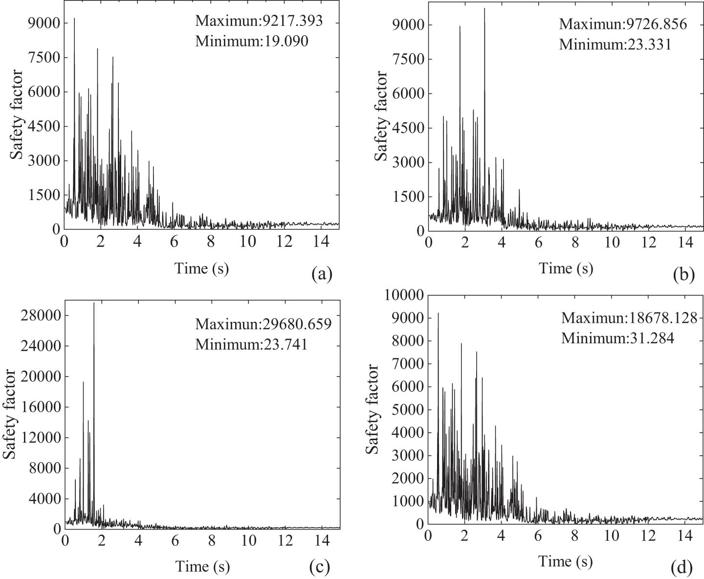
Safety factors of A19. (a) Original tunnel; (b) tunnel with the cushion; (c) tunnel with the partial buffer layer; and (d) tunnel with the integral buffer layer.
Minimum safety factor.
For the tunnel without the buffer layer, the minimum safety factor emerges at A15 and A23, 2.17 and 1.86, respectively. These two joints may suffer serious seismic injury under strong earthquakes, and isolation must be employed to increase the seismic behaviors. When the cushion scheme was adopted in the super-large pipe gallery, the minimum safety factor at A15 and A23 increases to 5.15 and 2.19, with a growth rate of 137.33 and 17.74%, respectively. Then, the minimum safety factor of A15 and A23 reaches 6.29 and 2.28, when the partial buffer layer was performed. Finally, while the gallery pipe was wrapped with the 10 cm thick sponge rubber plate, the minimum safety factor increases to 8.29 and 3.68, respectively. The application of four schemes increases the safety factor for the super-large pipe gallery.
To clarify, the seismic isolation effect is defined in equation (7), that is, the growth rate of the minimum safety factor of the gallery in Conditions 2–4 with respect to Condition 1. In this study, the A23, as the most dangerous position, is chosen to calculate the seismic isolation effect of three schemes, as listed in Table 6. To sum up, the integral sponge rubber plate has the most excellent seismic isolation effect (97.85%), followed by the partial buffer layer (22.58%) and the cushion (15.07%).
where
Seismic isolation effect
| Calculation conditions | Seismic schemes | Minimum safety factor | Seismic isolation effect (%) |
|---|---|---|---|
| 1 | — | 1.86 | — |
| 2 | Cushion scheme | 2.19 | 15.07 |
| 3 | Partial buffer layer | 2.28 | 22.58 |
| 4 | Integral buffer layer | 3.68 | 97.85 |
5 Conclusion
This study explores the seismic isolation scheme for the largest section shallow pipe gallery located in the seismic vulnerability area in China. The aseismic effects of three seismic approaches, namely, the cushion scheme, partial buffer layer, and integral buffer layer, were investigated. The various indexes including the lining deformation, the principal stress, the shear stress, as well as the safety factor, under the strong seismic motions were researched. Although the types and excitation directions of seismic motion, anisotropy of materials, and theoretical derivation have not been explored in this article, some significant conclusions can still be drawn:
The cushion scheme was found to reduce the lining deformation by 13.00%, the maximum and minimum principal stress by 29.66 and 5.20%, respectively, the maximum shear stress by 18.49%, and the safety factor by 15.07% for the super-large comprehensive pipe gallery tunnel.
After the partial buffer layer was employed, the lining deformation, the maximum and minimum principal stresses, maximum shear stress, and safety factor of the super-large pipe gallery present a reduction of 18.11, 33.90, 18.18, 31.86, and 22.58%, respectively.
When the integral buffer layer is adopted in the super-large comprehensive pipe gallery, the lining deformation decreases by 36.79%, the maximum and minimum principal stress decreases by 61.02 and 29.44%, the maximum shear stress decreases by 35.78%, and the minimum safety increases by 97.85%.
The cushion scheme, the partial buffer layer, and the integral buffer layer can all absorb and minimize the seismic motion on the tunnel structure, thus reducing the deformation, stress concentration, and internal force, and ultimately enhancing the seismic safety of the super-large pipe gallery. The integral buffer layer presents the most dramatic seismic isolation effect, followed by the partial buffer layer and the cushion scheme.
Based on the deformation, principal stresses, shear stress, and structural safety factor, the integral buffer layer is recommended for employing the seismic design for the present super-large pipe gallery.
-
Funding information: This work is supported by the National Natural Science Foundation of China (Grant Number: 52178378).
-
Author contributions: Conceptualization: G.C., S.H., and J.M.; methodology: S.H. and G.C.; investigation: G.C. and J.M.; data curation: G.C.; writing – original draft preparation: J.M. and X.L.; writing – review and editing: J.M. and X.L.; project administration: G.C. and S.H.; funding acquisition: G.C.
-
Conflict of interest: The authors declared that they have no conflicts of interest to this work.
-
Ethical approval: The conducted research is not related to either human or animal use.
-
Data availability statement: All data generated or analyzed during this study are included in this published article.
References
[1] Pan R, Wang Q, Jiang B, Li SC. Model test on failure and control mechanism of surrounding rocks in tunnels with super large sections. Arab J Geosci. 2019;12(22):687.10.1007/s12517-019-4863-5Search in Google Scholar
[2] Yue F, Liu BW, Zhu B, Jiang XL, Chen SY, Jaisee S, et al. Shaking table investigations on seismic performance of prefabricated corrugated steel utility tunnels. Tunn Undergr Space Technol. 2020;105:103579.10.1016/j.tust.2020.103579Search in Google Scholar
[3] Abbas M, Elbaz K, Shen S-L, Chen J. Earthquake effects on civil engineering structures and perspective mitigation solutions: A review. Arab J Geosci. 2021;14(14):1350.10.1007/s12517-021-07664-5Search in Google Scholar
[4] Azadi M, Hosseini S. Analyses of the effect of seismic behavior of shallow tunnels in liquefiable grounds. Tunn Undergr Space Technol. 2010;25(5):543–52.10.1016/j.tust.2010.03.003Search in Google Scholar
[5] Amorosi A, Boldini D. Numerical modelling of the transverse dynamic behaviour of circular tunnels in clayey soils. Soil Dyn Earthq Eng. 2009;29(6):1059–72.10.1016/j.soildyn.2008.12.004Search in Google Scholar
[6] Sloan SD, Nolan JJ, Broadfoot SW, McKenna JR, Metheny OM. Using near-surface seismic refraction tomography and multichannel analysis of surface waves to detect shallow tunnels: A feasibility study. J Appl Geophys. 2013;99:60–5.10.1016/j.jappgeo.2013.10.004Search in Google Scholar
[7] Kalab Z, Stemon P. Influence of seismic events on shallow geotechnical structures. Acta Montan Slov. 2017;22(4):412–21.Search in Google Scholar
[8] Wang FF, Jiang XL, Niu JY, Yang H. Experimental study on seismic dynamic characteristics of shallow-bias tunnel with a small space. Shock Vib. 2018;2018:9.10.1155/2018/6412841Search in Google Scholar
[9] Sun WY, Ma QG, Yan SH, Luo XX, Wang JH, Liang QG. Seismic response and damage characteristics of the shallow tunnel with asymmetric loess cover under the oblique incidence of seismic SV wave. Arab J Sci Eng. 2022;47:12535–53.10.1007/s13369-021-06533-3Search in Google Scholar
[10] Sun WY, Yan SH, Ma QG, Liang QG, Ou EF, Cao XP, et al. Dynamic response characteristics and failure mode of a bias loess tunnel using a shaking table model test. Transp Geotech. 2021;31:16.10.1016/j.trgeo.2021.100659Search in Google Scholar
[11] Wang XW, Chen JT, Zhang YT, Xiao M. Seismic responses and damage mechanisms of the structure in the portal section of a hydraulic tunnel in rock. Soil Dyn Earthq Eng. 2019;123:205–16.10.1016/j.soildyn.2019.04.026Search in Google Scholar
[12] An D, Chen Z, Cui GY. Research on seismic ground motion parameters applicable to the safety of rectangular shallow tunnel. Adv Mech Eng. 2022;14(1):10.10.1177/16878140211072627Search in Google Scholar
[13] Varma M, Maji VB, Boominathan A. Numerical modeling of a tunnel in jointed rocks subjected to seismic loading. Undergr Space. 2019;4(2):133–46.10.1016/j.undsp.2018.11.001Search in Google Scholar
[14] Pham V, Do NA, Dias D. Sub-rectangular tunnel behavior under seismic loading. Appl Sci-Basel. 2021;11(21):9909.10.3390/app11219909Search in Google Scholar
[15] Cui GY, Ma JF. Structure strengthening method for enhancing seismic behavior of soft tunnel portal section. Math Probl Eng. 2021;2021:12.10.1155/2021/6624963Search in Google Scholar
[16] Zheng Y, Yue C. Shaking table test study on the functionality of rubber isolation bearing used in underground structure subjected to earthquakes. Tunn Undergr Space Technol. 2020;98:103153.10.1016/j.tust.2019.103153Search in Google Scholar
[17] Shimamura S, Kasai H, Haruumi M. Seismic isolation effect for a tunnel with a soft isolation layer. Struct Eng Earthq Eng. 1999;16(2):143s–54s.10.2208/jscej.1999.626_27Search in Google Scholar
[18] Suzuki T, Takatori I, Okada I, Hagiwara R. New seismic isolation design for urban tunnels in consideration of slip and its application to an actual shield-driven tunnel. AITES-ITA Downunder 2002: 28th ITA General Assembly and World Tunnel Congress, Sydney, Australia, 2-8 March 2002: Modern Tunnels-Challenges and Solutions. Institution of Engineers; 2002. p. 708.Search in Google Scholar
[19] Wang M, Cui G. Study of the mechanism of shock absorption layer in the supporting system of tunnels in highly seismic areas. China Civ Eng J. 2011;44(8):126–31.Search in Google Scholar
[20] Ma S, Chen W, Zhao W. Mechanical properties and associated seismic isolation effects of foamed concrete layer in rock tunnel. J Rock Mech Geotech Eng. 2019;11(1):159–71.10.1016/j.jrmge.2018.06.006Search in Google Scholar
[21] Ministry of Housing and Urban-Rural Development of the People’s Republic of China. Technical code for urabn utility tunnel engineering. Beijing: China Planning Press; 2015.Search in Google Scholar
[22] MOHURD. Code for design of concrete structures. Beijing: China Construction Industry Press; 2011.Search in Google Scholar
[23] C.E.A. Institute of Geophysics. Seismic ground motion parameters zonation map of China; 2015. http://www.gb18306.cn. (Accessed 1 June 2016).Search in Google Scholar
[24] Salemi A, Mikaeil R, Haghshenas SS. Integration of finite difference method and genetic algorithm to seismic analysis of circular shallow tunnels (Case study: Tabriz urban railway tunnels). Ksce J Civ Eng. 2018;22(5):1978–90.10.1007/s12205-017-2039-ySearch in Google Scholar
[25] Cui G, Ma J. Application of thermal insulation layer in the tunnel with high temperature subjected to strong seismic motion. All Earth. 2021;33(1):124–35.10.1080/27669645.2021.1978162Search in Google Scholar
[26] Tsinidis G, de Silva F, Anastasopoulos I, Bilotta E, Bobet A, Hashash YMA, et al. Seismic behaviour of tunnels: From experiments to analysis. Tunn Undergr Space Technol. 2020;99:103334.10.1016/j.tust.2020.103334Search in Google Scholar
[27] Wang M, Cui G. Establishment of tunnel damping model and research on damping effect with model test in highly seismic area. Rock Soil Mech. 2010;31(6):1884–90.Search in Google Scholar
[28] Ministry of Transport of the Peoples’s Republic of China. Code for Design of Road Tunnel. Beijing, China: China Communication Publishing & Media Management Co., Ltd.; 2004.Search in Google Scholar
[29] Cui G, Ma J. Application of the isolation layer in tunnel crossing the soft and hard rock junction subjected to seismic waves. Jordan J Civ Eng 2021;15(2):241–52.Search in Google Scholar
© 2023 the author(s), published by De Gruyter
This work is licensed under the Creative Commons Attribution 4.0 International License.
Articles in the same Issue
- Research Articles
- Vibrational wave scattering in disordered ultra-thin film with integrated nanostructures
- Optimization of lead-free CsSnI3-based perovskite solar cell structure
- Determination of the velocity of seismic waves for the location of seismic station of Zatriq, Kosovo
- Seismic hazard analysis by neo-deterministic seismic hazard analysis approach (NDSHA) for Kosovo
- Ultimate strength of hyper-ellipse flanged-perforated plates under uniaxial compression loading
- Development of an adaptive coaxial concrete rheometer and rheological characterisation of fresh concrete
- Synthesis and characterization of a new complex based on antibiotic: Zirconium complex
- Exergy–energy analysis for a feasibility trigeneration system at Kocaeli University Umuttepe Campus
- Transient particle tracking microrheology of plasma coagulation via the intrinsic pathway
- Analysis of complex fluid discharge from consumer dispensing bottles using rheology and flow visualization
- A method of safety monitoring and measurement of overall frost heaving pressure of tunnel in seasonal frozen area
- Application of isolation technology in shallow super-large comprehensive pipe galleries in seismically vulnerable areas with weak soils
- Application of the ramp test from a closed cavity rheometer to obtain the steady-state shear viscosity η(γ̇)
- Research on large deformation control technology of highly weathered carbonaceous slate tunnel
- Tailoring a symmetry for material properties of tellurite glasses through tungsten(vi) oxide addition: Mechanical properties and gamma-ray transmissions properties
- An experimental investigation into the radiation-shielding performance of newly developed polyester containing recycled waste marble and bismuth oxide
- A study on the fractal and permeability characteristics of coal-based porous graphite for filtration and impregnation
- Creep behavior of layered salt rock under triaxial loading and unloading cycles
- Research and optimization of tunnel construction scheme for super-large span high-speed railway tunnel in poor tuff strata
- Elongational flow mixing: A novel innovative approach to elaborate high-performance SBR-based elastomer compounds
- The ductility performance of concrete using glass fiber mesh in beam specimens
- Thickened fluids classification based on the rheological and tribological characteristics
- Strength characteristics and damage constitutive model of sandstone under hydro-mechanical coupling
- Experimental study of uniaxial compressive mechanical properties of rough jointed rock masses based on 3D printing
- Study on stress distribution and extrusion load threshold of compressed filled rock joints
- Special Issue on Rheological Behavior and Engineering Stability of Rock Mass - Part II
- Seismic response and damage mechanism of tunnel lining in sensitive environment of soft rock stratum
- Correlation analysis of physical and mechanical parameters of inland fluvial-lacustrine soft soil based on different survey techniques
- An effective method for real-time estimation of slope stability with numerical back analysis based on particle swarm optimization
- An efficient method for computing slope reliability calculation based on rigorous limit equilibrium
- Mechanical behavior of a new similar material for weathered limestone in karst area: An experimental investigation
- Semi-analytical method for solving stresses in slope under general loading conditions
- Study on the risk of seepage field of Qiantang River underground space excavated in water-rich rheological rock area
- Numerical analysis of the impact of excavation for undercrossing Yellow River tunnel on adjacent bridge foundations
- Deformation rules of deep foundation pit of a subway station in Lanzhou collapsible loess stratum
- Development of fiber compound foaming agent and experimental study on application performance of foamed lightweight soil
- Monitoring and numerical simulation analysis of a pit-in-pit excavation of the first branch line of Lanzhou Metro
- CT measurement of damage characteristics of meso-structure of freeze-thawed granite in cold regions and preliminary exploration of its mechanical behavior during a single freeze-thaw process