High-Temperature Creep Behaviour and Positive Effect on Straightening Deformation of Q345c Continuous Casting Slab
-
Long Guo


Abstract
Mechanical and creep properties of Q345c continuous casting slab subjected to uniaxial tensile tests at high temperature were considered in this paper. The minimum creep strain rate and creep rupture life equations whose parameters are calculated by inverse-estimation using the regression analysis were derived based on experimental data. The minimum creep strain rate under constant stress increases with the increase of the temperature from 1000 °C to 1200 °C. A new casting machine curve with the aim of fully using high-temperature creep behaviour is proposed in this paper. The basic arc segment is cancelled in the new curve so that length of the straightening area can be extended and time of creep behaviour can be increased significantly. For the new casting machine curve, the maximum straightening strain rate at the slab surface is less than the minimum creep strain rate. So slab straightening deformation based on the steel creep behaviour at high temperature can be carried out in the process of Q345c steel continuous casting. The effect of creep property at high temperature on slab straightening deformation is positive. It is helpful for the design of new casting machine and improvement of old casting machine.
Introduction
Up to 2000s, continuous casting ratio has steadily increased. Steel continuous casting plays an important role in steel production [1]. The presence of cracks caused by bending and straightening in slabs is a critical defect during continuous casting. Creep in metals at high temperatures refers to time-dependent inelastic deformations that occur when temperature of the material exceeds 0.3–0.4 times of its absolute melting temperature [2, 3]. As the surface temperature of the slab is higher than 900 °C, the slab shows strong creep characteristics in present steel continuous casting production [4].
In the earlier years, Grill and Schwerdtfeger developed an elastic and creep model for the prediction of slab bulging [5]. Okamura and Kawashima studied the effect of creep on bulging deformation using three-dimensional elastic-plastic and creep finite element model [4]. The maximum value of the bulging by the elastic-plastic analysis is at most 0.16 mm. However, it increases to 0.23 mm when considering the creep effect, which is about 1.7 times of the value obtained by the elastic-plastic analysis. Ha, cho and their co-workers calculated the bulging deformation of casting slab using a two-dimensional elastic-plastic and creep finite element model [6]. The results were different due to different coefficients in the creep equation. They concluded that the bulging deflection caused by creep is dominant through comparing the results of experiment and analysis. Koric and Thomas studied two thermo-mechanical models based on different elastic-viscous-plastic constitutive laws which were applied to simulate temperature and stress development of a slice under typical commercial operating conditions with realistic temperature-dependent properties [7]. Li and Thomas developed an elastic-viscous-plastic creep constitutive equation to simulate temperature, stress, and shape development during the continuous casting of steel, both in and below the mould [8]. Suzuki et al. has done some researches about the creep characteristics of steel under casting temperature, the bulging deformation of slab and the generation of cracks, etc. [9]. These researches indicated that high temperature creep of the steel had significant influence on the deforming of the slab, which could not be neglected in the computation of deformation. The creep equation based on experimental creep data at high temperature of steel continuous casting was very helpful for calculating the deformation of slab accurately. It is necessary to investigate high-temperature creep property of steel continuous casting.
Fujimitsu Masuyama studied advances in technology related to the creep life prediction and damage evaluation for creep strength enhanced ferritic steels from the various aspects such as creep strength extrapolation methods, microstructures, modelling, and non-destructive and destructive testing in Japan [10]. Triratna Shrestha et al. had done some researches about creep rupture properties of the Grade 91 steel. They made an attempt to analyse the data in terms of creep fracture diagnostic approach on this important steel under welded condition [11]. Adriano Gonçalves dos Reis et al. investigated the high-temperature creep resistance and its effects on the austenite reversion and the dynamic evolution of precipitates of 18 Ni (300) maraging steel [12]. D.Q. Zhou et al. had done researches about precipitate characteristics and their effects on the high-temperature creep resistance of alumina-forming austenitic stainless steels [13]. These researches indicated that the lifetime of components operating is limited by the mechanisms of creep. Also creep behaviour is regarded as a kind of harmful deformation and it should be resisted from original design. There are few literatures related to the study of positive effects of high-temperature creep behaviour on steel casting.
In this research, creep deformation in metals with small loads is obvious at high temperatures and the high-temperature creep deformation can be fully used in the processing of bending and straightening of steel slab continuous casting. Based on the elastic-plastic theory, the stress within the elastic limit will not lead to material permanent deformation. However, at the high temperature the permanent deformation of material occurs although the stress is less than yield strength. This is steel creep deformation but not plastic deformation. Steel creep rate at high temperature is much higher than it at normal temperature. Therefore, attempt has been made in this research to illustrate the positive effects of high-temperature creep behaviour on straightening deformation of steel continuous casting. Continuous casting slab is straightened by means of creep deformation so as to reduce the straightening strain rate substantially. It is helpful to avoid the slab cracks effectively and improve the productivity of the caster.
Experimental
A number of researchers had done amount of tensile tests on the study of creep behaviour using a variety of different materials [14, 15, 16]. In this paper, uniaxial tensile tests of Q345c continuous casting slab were carried out by the Gleeble-3800 in order to evaluate high-temperature mechanical properties and its creep behaviour.
Q345c steel involved in this paper was procured in the form of continuous casting slab. The chemical composition of this steel is given in Table 1. The specimen in 10 mm diameter by 120 mm long threaded at both ends is shown in Figure 1. All of specimens was given a typical in situ melting thermal history and interrupted cooling cycle before testing. In order to simulate the process of steel continuous casting, the heating rate was 10 °C/s and holding the temperature 1320 °C for 2 minutes. Controlled cooling rate to the tensile test temperature was 3 °C/s and holding time the temperature before tensile testing is 3 minutes [17, 18]. Uniaxial tensile tests of the specimens by 0.01 s−1 constant strain rate were carried out so as to evaluate high-temperature mechanical properties. Constant stress tensile creep tests of specimens were performed at temperatures from 1100 to 1200 °C with the stress less than yield strength corresponding to these temperatures. The parameters of creep tensile test are listed in Table 2.

Uniaxial tensile specimen.
Chemical composition of Q345c.
| Steel | C [%] | Si [%] | Mn [%] | P [%] | S [%] | V [%] | Ti [%] |
|---|---|---|---|---|---|---|---|
| Q345c | 0.2 | 0.50 | 1.65 | 0.030 | 0.035 | 0.18 | 0.11 |
Parameters of creep tensile test.
| Temperature [°C] | Yield strength [MPa] | Applied stress [MPa] | |||
|---|---|---|---|---|---|
| 1100 | 19.21 | 15.28 | 16.55 | 17.82 | 19.10 |
| 1150 | 17.25 | 12.73 | 14.00 | 15.28 | 16.55 |
| 1200 | 15.61 | 10.18 | 11.46 | 12.73 | 14.00 |
Results
Mechanical properties
The reduction in area (RA) of Q345c at different temperature is shown in Figure 2. The results indicate that the material should have a very bad plasticity in the temperature range of 1000 °C to 1100 °C. There is a good plastic zone between 1100 °C to 1200 °C with the recovery of ductility. According to the stress–strain experimental data, numerical data of 0.2 offset yield strength of Q345c steel at temperatures of 800 to 1200 °C are given in Figure 3.

Reduction in area versus temperature.

Yield strength (σ0.2) versus temperature.
It is visible that 0.2 offset yield strength (σ0.2) decreases with temperature increasing. Because of the bad plasticity at 1050 °C from Figure 2, yield strength of the material decreases rapidly at temperature of 1050 to 1100 °C. Combined with Figures 2 and 3, it can be seen that yield strength decreases slowly if the material has good plasticity and vice versa. When material is stressed within the yield strength, plastic deformation will not result. Based on these values of yield strength at different high temperature, it is easy to distinguish plastic strain from total strain.
Creep properties
In order to achieve the steel creep characteristics at high temperature, tensile creep tests with the parameters of temperature and load in Table 2 were carried out. As the stress is less than yield strength, only creep strain occurred without plastic strain. The creep strain changes with time under different temperature and load. The test results are shown in Figure 4.
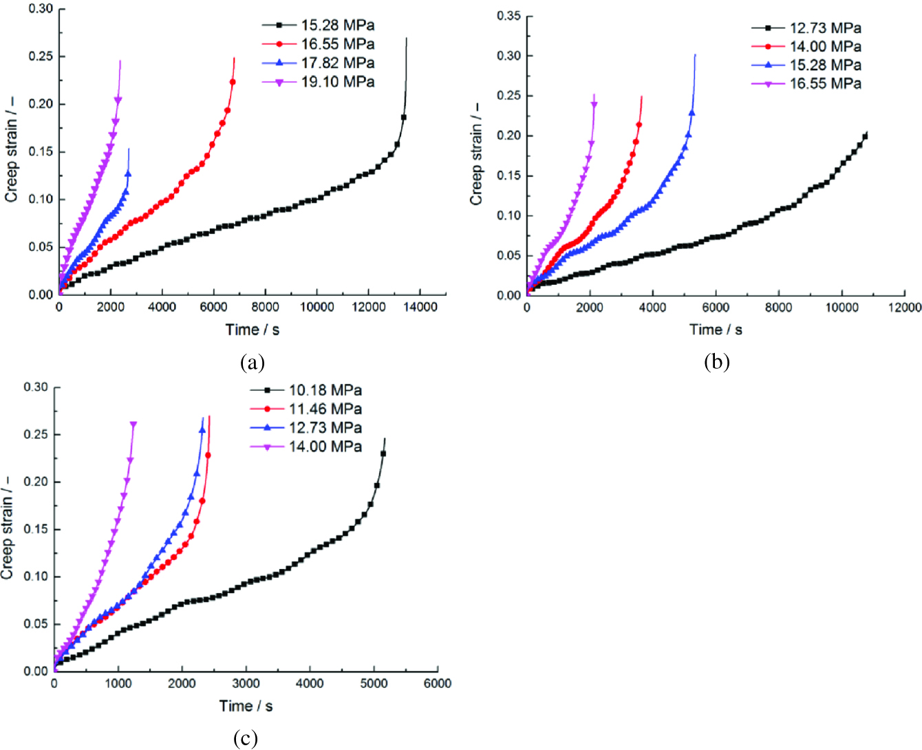
Tensile creep curves at 1100 °C, 1150 °C and 1200 °C: (a) 1100 °C, (b) 1150 °C and (c) 1200 °C.
Firstly there is a relatively short initial period in which the creep strain increases at variable rate. And then there is long period with the creep strain increasing at constant rate. Lastly creep strain increases rapidly and fracture occurs. It is also observed that increasing of load and temperature accelerates the creep rate and thereby decreases the range of steady state from Figure 4.
For most metal and alloys, minimum creep strain rate can be described by the power-law creep equation [12, 19]. The simple creep law relates the minimum creep rate
where Qc is the activation energy for creep. A is a constant which depends on the microstructure, temperature and applied stress. n is stress exponent. R is universal gas constant.

Curve of creep strain rate.
Minimum creep rate and rupture time.
| Temperature [°C] | Applied stress [MPa] | Minimum creep strain rate [s−1] | Creep rupture time [s] |
|---|---|---|---|
| 1100 | 15.28 | 1.01×10⁻⁵ | 13464 |
| 16.55 | 2.36×10⁻⁵ | 6788 | |
| 17.82 | 3.88×10⁻⁵ | 2699 | |
| 19.10 | 7.45×10⁻⁵ | 2365 | |
| 1150 | 12.73 | 1.15×10⁻⁵ | 10802 |
| 14.00 | 2.57×10⁻⁵ | 5337 | |
| 15.28 | 4.18×10⁻⁵ | 3464 | |
| 16.55 | 6.69×10⁻⁵ | 2142 | |
| 1200 | 10.18 | 3.04×10⁻⁵ | 5172 |
| 11.46 | 6.24×10⁻⁵ | 2427 | |
| 12.73 | 6.39×10⁻⁵ | 2327 | |
| 14.00 | 7.45×10⁻⁵ | 2365 |
Take the logarithm of eq. (1).
In eq. (2),

Dependence of minimum creep strain rate on applied stress for Q345c at 1100 °C, 1150 °C and 1200 °C (the slope is n).

Dependence of minimum creep strain rate on temperature for Q345c at 1100 °C, 1150 °C and 1200 °C (the slope is -Qc/R).
The relationship of the minimum creep rate, the applied stress σ and temperature T can be expressed by eq. (3).
The relationship between the minimum creep rate and rupture life is given by the Monkman-Grant equation [20].
where
It is obtained that m equals to 0.8987 and C equals to 0.403 from the fitted straight line of the logarithmic relation in Figure 8. Thus, the creep rupture life can be predicted by eq. (4) based on the experimentally determined minimum creep rate.

Relationship of minimum creep strain rate and rupture time.
Discussion
As creep strain rate is bigger at high temperature, creep deformation of slabs plays an important role during bending and straightening of steel continuous casting. The relationship of minimum creep strain rate with straightening strain rate in the process of straightening deformation of slab needs to be paid more attention as follows:
When
When
There are two different theories to calculate the slab bending or straightening strain: the soft box and the hard box. In the soft box approach, it is assumed that the restraining effect of narrow face can be neglected. The top and bottom layers of the slab deform independently with separate neutral axes. The hard box approach is more accurate to calculate the strain when the restraining effect of narrow face cannot be neglected. In this research, the hard approach is used. Therefore, the neutral axis is assumed to lie at the centre of the slab. The tensile strain at the surface of slab caused by bending and straightening can be calculated using eq. (6) [21, 22].
where D is slab thickness, ki and ki+1 are the curvatures at the starting point and the end point of straightening curve. It is obvious that the variation of curvature radius leads to slab straightening strain. So there is no deformation at the zoon of the basic arc segment of casting machine. For current slab bending and straightening methods, the arc length of bending and straightening segments are comparatively short. The strain rate changes abruptly at the point of bending or straightening. So creep behaviour is not fully used.
In this paper, the R9300 vertical-arc slab casting machine with five-point bending and five-point straightening is considered. Its main parameters are shown in Table 4. There is a long basic arc segment between bending and straightening segments.
Parameters of R9300 casting machine curve.
| Parameters of curves | R9300 casting curve |
|---|---|
| Basic arc length [mm] | 13300 |
| Vertical segment [mm] | 1465 |
| Bending segment [mm] | 1030 |
| Straightening segment [mm] | 1520 |
| Height of casting machine [mm] | 12305.55 |
| Metallurgical length [mm] | 35862 |
| Curvature radius of bending segment [mm] | |
| 49420.834 | |
| 24328.140 | |
| 15971.287 | |
| 11797.719 | |
| Curvature radius at intersection [mm] | 9300 |
| Curvature radius of straightening segment [mm] | 11312.892 |
| 14671.987 | |
| 21396.378 | |
| 41581.549 | |
Based on the parameters of R9300 casting machine, a new casting curve with continuous bending and continuous straightening segments is proposed. There is not basic arc segment between bending and straightening segments. The arc length of bending segment is 8000 mm and the arc length of straightening segment is 12274 mm. The curvature radius at connecting point between bending and straightening segments should be 9000 mm so as to minimize the change of origin R9300 casting machine. In order to make full use of creep behaviour during the slab straightening process, the straightening zone is extended and basic arc segment is cancelled. The curves of bending segment and straightening segment can be drawn by eqs 7 and 8. The bending curve in the
The bending curve equation in the
The straightening curve equation in the
Figure 9 shows the eventual new curve of casting machine in the same coordinate system. It can be seen that the height of new curve is 11991.7 mm, the arc length of bending segment is 8000 mm and the arc length of straightening segment is 12274 mm from Figure 9. The metallurgical length of new curve is 35862 mm as same as the original R9300 casting machine.
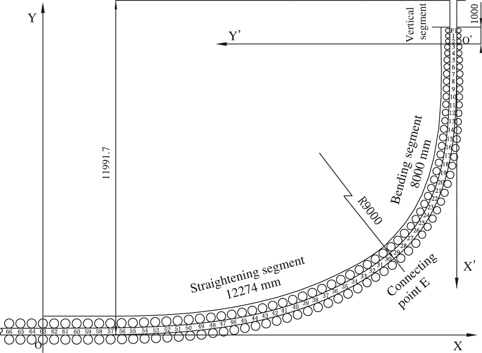
New roller curve of casting machine in the same coordinate system.
The curvature changes continuously along the arc length.
The curvature of bending segment is
The curvature of straightening segment is
For continuous straightening curves, the strain rate at the surface can be expressed as eq. (11).
where

Strain rate at surface of inner the slab in new casting machine curve.
Minimum creep rate under close to yield strength at 1000 °C to 1200 °C.
| Temperature [°C] | Yield strength [MPa] | Applied stress [MPa] | Minimum creep strain rate [s−1] |
|---|---|---|---|
| 1000 | 32.57 | 30.5 | 3.4×10⁻⁵ |
| 1050 | 25.99 | 23.5 | 3.7×10⁻⁵ |
| 1100 | 19.21 | 18.5 | 4.2×10⁻⁵ |
| 1150 | 17.25 | 16 | 7.7×10⁻⁵ |
| 1200 | 15.61 | 13 | 8.4×10⁻⁵ |
Conclusion
The creep behaviour and mechanical properties of Q345c steel at high temperature are studied in this paper. A new casting machine curve fully using of high-temperature creep behaviour is proposed in present work. The positive effects of creep deformation on straightening deformation in continuous casting production are analysed. Some important conclusions can be constructed as follows:
The minimum creep strain rate equation is derived based on power-law creep equation. Using the Monkman-Grant equation the creep rupture life can be predicted based on the experimentally determined minimum creep rate. The creep parameters are calculated by using regression method based on the experimental data. It is observed that increase in load and temperature accelerates the creep rate thereby decreases the steady-state range. The minimum creep strain rate under constant stress which is less than yield strength increases with temperature increasing in the range of 1000 °C to 1200 °C.
A new casting machine curve for fully taking advantage of steel high-temperature creep behaviour is proposed in this paper. For the new curve, the basic arc segment is cancelled so that length of the straightening zoon can be extended and creep time can be increased significantly. The maximum straightening strain rate at the slab surface is less than the minimum creep strain rate. So in the process of steel Q345c continuous casting the slab straightening deformation is steel creep deformation. And the straightening tress is less than the yield strength and will not result in cracks. The effect of creep property at high temperature on straightening deformation of slab is positive. This research is helpful for the design of new casting machine and the improvement of old casting machine.
Funding statement: This research was financially supported by the National Science Foundation of China under the Grant No. 51275446, the Hebei Provincial Natural Science Foundation of China under the Project No. E2016203492. The authors thank the National Science Foundation of China and Hebei Provincial Natural Science Foundation of China for funding of this research work.
References
[1] H. Tomono, Ironmaking Steelmaking, 42 (2015) 242–251.10.1179/0301923315Z.000000000356Search in Google Scholar
[2] M.F. Ashby and D.R.H. Jones, Engineering Materials 1: An Introduction to Properties, Applications and Design, Elsevier Science, New York (2011).10.1016/B978-1-85617-663-7.00003-5Search in Google Scholar
[3] N. Ottosen and M. Ristinmaa, The Mechanics of Constitutive Modeling, Elsevier, Amsterdam (2005).Search in Google Scholar
[4] K. Okamura and H. Kawashima, ISIJ Int., 29 (1989) 666–672.10.2355/isijinternational.29.666Search in Google Scholar
[5] A. Grill and K. Schwerdtfeger, Ironmaking Steelmaking, 6 (1979) 131–135.Search in Google Scholar
[6] J.S. Ha, J.R. Cho, B.Y. Lee and M.Y. Ha, J. Mater. Process. Technol., 113 (2001) 257–261.10.1016/S0924-0136(01)00654-9Search in Google Scholar
[7] S. Koric and B.G. Thomas, J. Mater. Process. Technol., 197 (2008) 408–418.10.1016/j.jmatprotec.2007.06.060Search in Google Scholar
[8] C. Li and B.G. Thomas, Metall. Mater. Trans. B, 35 (2004) 1151–1172.10.1007/s11663-004-0071-zSearch in Google Scholar
[9] T. Suzuki, K.H. Tacke and K. Wuennenberg, Ironmaking Steelmaking, 15 (1988) 90–100.Search in Google Scholar
[10] F. Masuyama, Mater. High Temp., 28 (2014) 234–244.10.3184/096034011X13123829786079Search in Google Scholar
[11] T. Shrestha, M. Basirat, S. Alsagabi, A. Sittiho, I. Charit and G.P. Potirniche, Mater. Sci. Eng., A, 669 (2016) 75–86.10.1016/j.msea.2016.05.065Search in Google Scholar
[12] A.G.D. Reis, D.A.P. Reis, A.J. Abdalla and G. Otubo, Mater. Charact., 107 (2015) 350–357.10.1016/j.matchar.2015.08.002Search in Google Scholar
[13] D.Q. Zhou, W.X. Zhao, H.H. Mao, Y.X. Hu, X.Q. Xu, X.Y. Sun and Z.P. Lu, Mater. Sci. Eng. A, 622 (2015) 91–100.10.1016/j.msea.2014.11.013Search in Google Scholar
[14] A.S. Mammar, D. Gruber, H. Harmuth and S.L. Jin, Ceram. Int., 42 (2016) 6791–6799.10.1016/j.ceramint.2016.01.056Search in Google Scholar
[15] J. Brnic, M. Canadija and G. Turkalj, Bull. Mater. Sci., 33 (2010) 475–481.10.1007/s12034-010-0073-1Search in Google Scholar
[16] M. Cowan and K. Khandelwal, Eng. Struct., 80 (2014) 426–434.10.1016/j.engstruct.2014.09.020Search in Google Scholar
[17] Z.H. Dong, Chin. J. Mater. Res., 27 (2013) 273–278.10.1007/s40290-013-0023-5Search in Google Scholar
[18] X.D. Kang, H.S. Dong and X.M. Zhang, J. Northeast. Univ., 25 (2004) 40–43.Search in Google Scholar
[19] M. Brunner, R. Hüttner, M.C. Bölitz, R. Völkl, D. Mukherji, J. Rösler, T. Depka, C. Somsen, G. Eggeler and U. Glatzel, Mater. Sci. Eng. A, 528 (2010) 650–656.10.1016/j.msea.2010.09.035Search in Google Scholar
[20] F.C. Monkman and N.J. Gran, Proc. ASTM., 56 (1956) 593–620.10.1097/00000446-195605000-00030Search in Google Scholar
[21] Y.P. Sheng, J.Q. Sun and M. Zhang, Iron Steel, 28 (1993) 20–25.Search in Google Scholar
[22] R.K. Verma and N.U. Girase, Ironmaking Steelmaking, 33 (2006) 471–476.10.1179/174328106X149815Search in Google Scholar
© 2018 Walter de Gruyter GmbH, Berlin/Boston
This article is distributed under the terms of the Creative Commons Attribution Non-Commercial License, which permits unrestricted non-commercial use, distribution, and reproduction in any medium, provided the original work is properly cited.
Articles in the same Issue
- Frontmatter
- Research Articles
- Effect of the Basicity on the Crystallization Behavior of Titanium Bearing Blast Furnace Slag
- Distribution Behavior of B and P during Al-Si Melt Directional Solidification with Open-Ended Crucible
- Effect of CeO2 on TiC Morphology in Ni-Based Composite Coating
- Studies on the Parametric Effects of Plasma Arc Welding of 2205 Duplex Stainless Steel
- Finite Element Analysis of Surface Residual Stress in Functionally Gradient Cemented Carbide Tool
- Effect of Sulfur and Chlorine on Fireside Corrosion Behavior of Inconel 740 H Superalloy
- High-Temperature Creep Behaviour and Positive Effect on Straightening Deformation of Q345c Continuous Casting Slab
- Effects of Rare Earth Lanthanum on the Solidification Structure and Hot Ductility of Fe-43Ni Expansion Alloy
- Influence of Heat Treatment on γ´ Phase and Property of a Directionally Solidified Superalloy
- An Abnormal Increase of Fatigue Life with Dwell Time during Creep-Fatigue Deformation for Directionally Solidified Ni-Based Superalloy DZ445
- Competition between Chemical and Gravity Forces in Binary Alloys