Performance optimization of flywheel using experimental design approach
-
Abdelbaki Abdallah

 and
Mokhtar Bounazef
and
Mokhtar Bounazef

Abstract
The flywheel is the simplest device for mechanical battery that can charge/discharge electricity by converting it into the kinetic energy of a rotating flywheel, and vice versa. The energy storage systems based on flywheel now arousing great interest, since this technology can offer great advantages in durability and lifetime. However, the flywheel performance rotation is limited by the strength of the materials, from which it is constructed, and the geometry. Greater control over those parameters could improve the development of high performance of a flywheel energy storage system (FESS). The main interest of this study is to demonstrate the influence degree of each parameter of geometry by using the mathematical method of design of experiments, in order to be able to optimize the adequate parameters for a high performed shape of the flywheel.
Introduction
Flywheels have been used for a long time as mechanical energy storage devices; one of the earliest forms is a potter’s wheel. Today, the flywheels are a practical and attractive solution for energy storage technologies. The recent improvements in materials, magnetic bearings, power electronics, and the introduction of high speed electric machines, has re-emerged, the flywheel, as a promising for energy storage applications (Bakay et al. 2010; Bolund, Bernhoff, and Leijon 2007; Conteh and Emmanuel 2016; Erhan and Ozdemir 2021; Haruna et al. 2011; Liu and Jiang 2007; Murakami et al. 2007; Šonský and Tesař 2019). Compared to a chemical battery, the FESS has great advantages in durability and lifetime, especially in hot or cold environments (Takahashi, Amei, and Itoh 1990; Takahashi, Itoh, and Andoh 1989), that makes it an appealing candidate for a wider use in renewable energy systems and become an attractive battery alternative. The storage capacity of flywheel depends on the rotational speed and the moment of inertia; which they are closely related to the form of rotor.
Many research works have been done on flywheel geometry. A study of flywheel geometry by Shinde et al. (2017) showed that flywheel with triangular cross-sectional geometry is more efficient than compared to the rectangular and circular cross-section of geometry. A similar study was done by Pawar et al. (2018); after performing a series of finite element analysis, it was observed that with the change in flywheel geometry and its material, there is a significant effect on the performance with a reduction in weight of the flywheel. More recently, a study conducted by Vardaan and Kumar (2022) where they carried out the analysis of the thresher machine flywheel. The authors concluded that the amount of kinetic energy stored by wheel-shaped structure flywheel is greater than any other shape of the flywheel. Therefore, it can be noted that the effect of geometry plays a significant role in flywheel performance.
The purpose of this study is to demonstrate how to find the most efficient geometry in order to increase the performance of the flywheel. A virtual 3D model of the flywheel is designed and analyzed, which provides a database of the design for mathematical modeling and optimization of the flywheel.
Flywheel modelling & simulation
In the present study, among parameters defining the flywheel geometry, three of them were taken under considerations which seem to have significant influence on the flywheel performance. As demonstrated elsewhere (Chiriță et al. 2017), the outer diameter, the rim width and the rim height have a remarkable effect on the specific energy accumulated by the flywheel. However, an increasing of the thickness of the disc leads to a decrease in the specific energy. The geometry parameters are given in Table 1 and illustrated in Figure 1.
Geometry parameters of the flywheel.
| Geometry parameter | Rim | Rim | Rim | Disk | Hub | Hub | Hub |
|---|---|---|---|---|---|---|---|
| Diameter | Width | Height | Thickness | Diameter | Gap | Height | |
| Designation | Dr | Wr | Hr | Td | Dh | Gh | Hh |
| Value (mm) | Variable | Variable | Variable | 2 | 20 | 5 | 10 |

Section view of 3D model of the flywheel.
In order, to optimize the performance of the flywheel, different configurations have been created and analyzed by using SolidWorks software. The flywheel was considered of Titanium alloy material (Ti-3Al-8V-6Cr-4Mo-4Zr) with the mechanical properties as noted in Table 2, rotating at 70,000 rpm, which correspond to an angular velocity of 7330.38 rad/s.
Mechanical proprieties of the flywheel material.
| Material | Density (kg m−3) | Tensile strength (MPa) | Young’s modulus (GPa) | Yield strength (MPa) |
|---|---|---|---|---|
| Ti-3Al-8V-6Cr-4Mo-4Zr | 4820 | 1220 | 104 | 1034.21 |
A total of 27 configurations of the flywheel geometry has been created, simulated and optimized. Therefore, using the capabilities of Evaluate tool in SolidWorks, the flywheel mass (m) and the moment of inertia (I) have been defined. Then, the kinetic energy (Ec) stored in the flywheel (Eq. (1)) and the specific energy (Espec) in Eq. (2), were calculated with the formulas below:
The present study was conducted such that highlights the varying effect of the geometry parameters, on the mechanical stress of the flywheel. SolidWorks Simulation is powerful Finite Element Analysis (FEA) software, that allowed to determine the maximum stresses in the flywheel for each analyzed 3D model configurations.
The geometry parameter values, the mass, the moment of inertia, the kinetic and specific energy and the maximum of Von-Mises stress values are given in Table 3.
Configurations & Calculated parameters of flywheel.
| N° | Dr (mm) | Wr (mm) | Hr (mm) | Mass (Kg) | Inertia (Kg mm−2) | Kinetic Energy (J) | Specific Energy (J/Kg) | Von-Mises Stress (MPa) |
|---|---|---|---|---|---|---|---|---|
| 01 | 100 | 4 | 10 | 0.13 | 202.561 | 5442.259 | 41863.527 | 465.584 |
| 02 | 100 | 4 | 20 | 0.188 | 336.765 | 9047.952 | 48127.404 | 577.373 |
| 03 | 100 | 4 | 30 | 0.246 | 470.968 | 12653.619 | 51437.474 | 593.85 |
| 04 | 100 | 6 | 10 | 0.152 | 246.738 | 6629.173 | 43612.983 | 515.318 |
| 05 | 100 | 6 | 20 | 0.237 | 436.164 | 11718.530 | 49445.276 | 657.958 |
| 06 | 100 | 6 | 30 | 0.323 | 625.589 | 16807.861 | 52036.721 | 728.424 |
| 07 | 100 | 8 | 10 | 0.173 | 285.285 | 7664.826 | 44305.350 | 560.011 |
| 08 | 100 | 8 | 20 | 0.284 | 522.894 | 14048.728 | 49467.351 | 706.261 |
| 09 | 100 | 8 | 30 | 0.396 | 760.502 | 20432.603 | 51597.482 | 771.789 |
| 10 | 110 | 4 | 10 | 0.151 | 283.606 | 7619.715 | 50461.692 | 558.905 |
| 11 | 110 | 4 | 20 | 0.215 | 464.212 | 12472.103 | 58009.783 | 699.461 |
| 12 | 110 | 4 | 30 | 0.279 | 644.818 | 17324.491 | 62094.951 | 742.946 |
| 13 | 110 | 6 | 10 | 0.175 | 344.2 | 9247.710 | 52844.057 | 600.194 |
| 14 | 110 | 6 | 20 | 0.27 | 600.549 | 16135.105 | 59759.647 | 768.725 |
| 15 | 110 | 6 | 30 | 0.364 | 856.898 | 23022.499 | 63248.624 | 855.202 |
| 16 | 110 | 8 | 10 | 0.198 | 397.812 | 10688.117 | 53980.391 | 659.851 |
| 17 | 110 | 8 | 20 | 0.322 | 721.175 | 19375.994 | 60173.896 | 859.464 |
| 18 | 110 | 8 | 30 | 0.445 | 1044.538 | 28063.871 | 63064.879 | 926.309 |
| 19 | 120 | 4 | 10 | 0.173 | 386.116 | 10373.87798 | 59964.61262 | 652.607 |
| 20 | 120 | 4 | 20 | 0.243 | 622.755 | 16731.71892 | 68854.81038 | 797.407 |
| 21 | 120 | 4 | 30 | 0.314 | 859.395 | 23089.58673 | 73533.71569 | 856.655 |
| 22 | 120 | 6 | 10 | 0.2 | 466.761 | 12540.58796 | 62702.9398 | 715.09 |
| 23 | 120 | 6 | 20 | 0.303 | 804.207 | 21606.83652 | 71309.69149 | 930.909 |
| 24 | 120 | 6 | 30 | 0.407 | 1141.653 | 30673.08508 | 75363.84542 | 1027.426 |
| 25 | 120 | 8 | 10 | 0.225 | 538.926 | 14479.4636 | 64353.17154 | 751.406 |
| 26 | 120 | 8 | 20 | 0.361 | 966.579 | 25969.32685 | 71937.19349 | 994.369 |
| 27 | 120 | 8 | 30 | 0.497 | 1394.232 | 37459.19011 | 75370.60384 | 1099.517 |
Mathematical modelling
In order to investigate the effect of geometry parameters on the flywheel performance under high speed rotation, the modelling by the mathematical method of design of experiments seems adequate. By using the functionalities of MODDE, a software package that is used by scientists, engineers and statisticians alike to help understand complex processes and products (Umetrics™ 2017), the study was conducted using the No-conventional design of experiments, which allow to use the obtained data to establish a mathematical model that makes possible to evaluate the degree of the effect of each parameter separately and their simultaneous interaction, on the accumulated energy and the mechanical stress of the flywheel. Then, according to the desired limit of response, the geometry parameters will be optimized to reach the best possible solution.
Mathematical models
Mathematical modelling by design of experiments is done by a polynomial of a second degree equation (Eq. (3)).
After estimating the coefficients, using the capabilities of Edit Model tool in MODDE (Umetrics™ 2017), the mathematical models of the specific energy response (Eq. (4)) and Von-Mises stress response (Eq. (5)) are established.
x1: represent the coefficient of rim diameter;
x2: represent the coefficient of rim width;
x3: represent the coefficient of rim height;
yEspec: represent the response of specific energy;
yVMs: represent the response of Von-Mises stress;
It is important to note that the model validity (R2) and reproducibility (Q2) qualities of coefficients estimated above are acceptable (Table 4), which ensure the validation of the mathematical models to be exploited in further studies.
Summary of coefficient qualities list.
| Specific energy | Von-Mises stress | |
|---|---|---|
| Model validity (R2) | 0.990816 | 0.968959 |
| Reproducibility (Q2) | 0.983968 | 0.939926 |
The effect of geometry parameters
Figure 2 is a graphical presentation of the estimated coefficients of the mathematical models. From the vertical bars of the diagram results that, in general, the effects of parameters separately appear to have a positive act on the increase of the specific energy. The rim diameter (Dr) and rim height (Hr) presents a relatively large effect compared to that of width rim (Wr). Although, the effects of parameters separately might increase the maximum value of Von-Mises stress. The rim diameter shows the highest effect, followed by rim height and relatively less important effect of width rim.
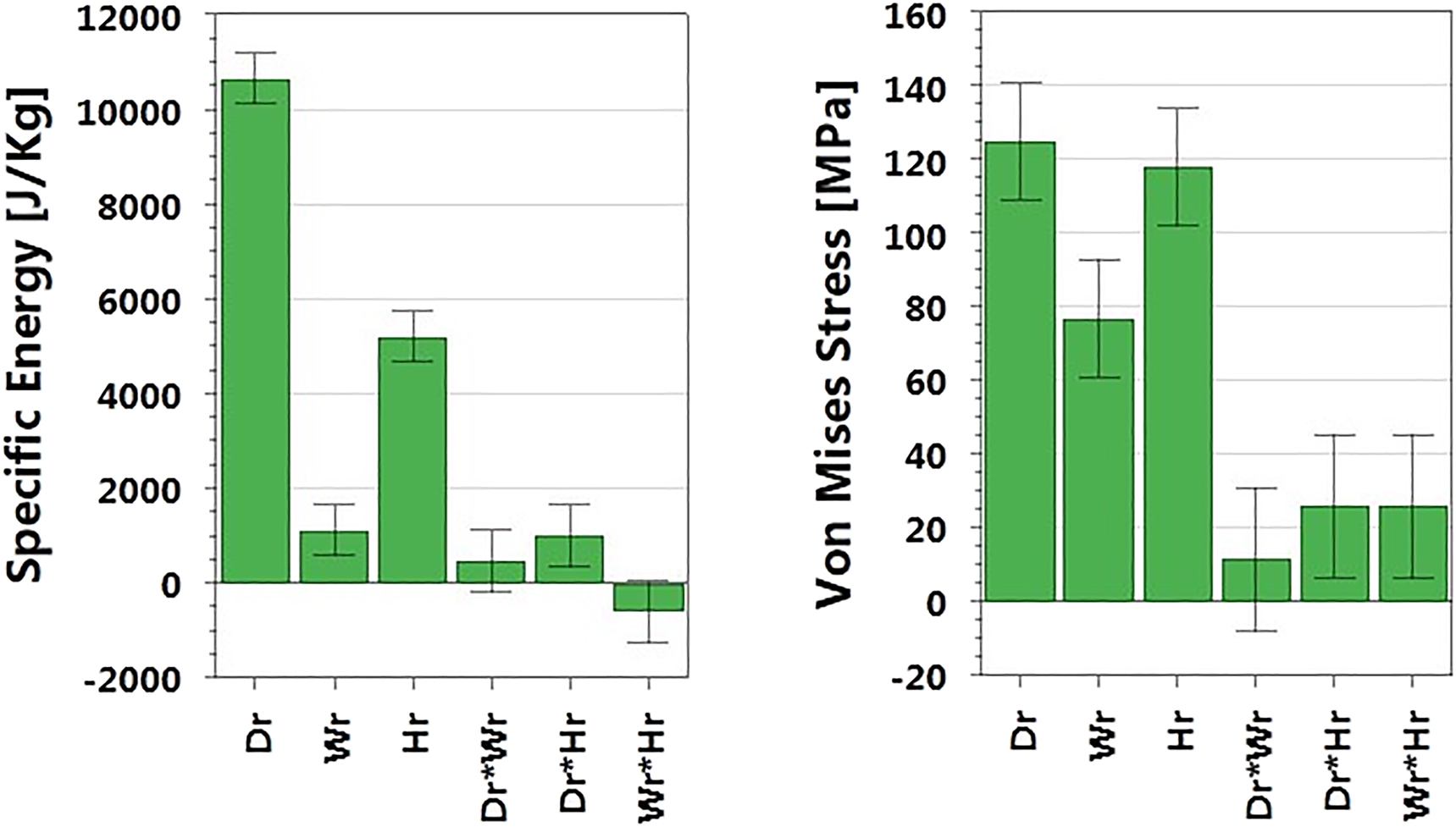
Diagram representation of the parameters effects.
On the other hand, the interaction effect of Dr*Wr and Dr*Hr. leads to an increasing of the specific energy. However, the simultaneous increase of Wr*Hr, may negatively affect on this last and even on Von-Mises stress by increasing its maximum value. The highest and lowest interaction effect on Von-Mises stress are shown successively by Dr*Hr and Dr*Wr interaction of parameters.
Optimization of parameters
The aim of this part is to design a flywheel with a high energy storage density and supporting high speed. By observing the effect of Wr and Hr separately, which is positive on the specific energy and their interaction (Wr * Hr) which seems has a negative effect; for this reason, care has to be taken in manipulating the values of design parameters. Therefore, it is appropriate to apply the optimization of geometry parameters in the design of flywheel; by using the capabilities of Optimizer tool on MODDE, which helps on how to find the optimal conditions or best compromise as a set point and alternatively the most robust set point.
In general, flywheel designs are subject to size constraints in addition to stress constraints. Actually, the load on the flywheel is mainly centrifugal force. Therefore, the objective of optimization is based on a combination of reducing the stress constrains applied to the flywheel and reaching the highest level of energy storage density (Table 5).
Optimization.
| Parameters | Objective | Optimized value |
|---|---|---|
| Specific energy (J/Kg) | Maximize | 73533.715 |
| Von-Mises stress (MPa) | >Yield strength | 856.655 |
| Rim diameter (mm) | Free | 120 |
| Rim width (mm) | Free | 4 |
| Rim height (mm) | Free | 30 |
-
The bold values represent the optimized values calculated by the software “MODDE”.
Table 5, shows the optimized values of geometry parameters, with the goal of maximizing the specific energy while minimizing Von-Mises stress, such a way that the high value of the stress constraints, shall be less than the yield strength of the flywheel material. The table exposed the design parameter values which allow to obtain the highest possible value of specific energy under minimum values of applied stress constraints and without exceeding the Yield strength. It is noted that the optimized values of rim diameter and rim height, reached their maximum levels, however, it reached its lowest level for the rim width. As demonstrated previously, the simultaneous increase of geometry parameters can have a negative effect on responses.
The optimized values of design parameters of the flywheel, at constant rim diameter values of 105 and 115 mm, are shown in Table 6. The specific energy exhibited a high value for the configuration M115, about 16% more than for M105. This result was achieved with a relatively little decrease of the rest of the parameters. A remarkable increase of von-mises stress value is noted for M115, without certainly exceeding the yield strength.
Optimization at a constant rim diameter (Dr = Cst).
| Parameters | Objective | Optimized value | Optimized value |
|---|---|---|---|
| Configuration | M105 | M115 | |
| Specific energy (J/Kg) | Maximize | 58131.2 | 69928.7 |
| Von-mises stress (MPa) | Minimize | 882.967 | 1002.18 |
| Rim diameter (mm) | Constant | 105 | 115 |
| Rim width (mm) | Free | 8 | 7.20 |
| Rim height (mm) | Free | 30 | 29.99 |
-
The bold values represent the optimized values calculated by the software “MODDE”.
In Table 7, the optimized values of design parameters of the flywheel are obtained at constant rim width values of 5 and 7 mm. From the table, it is noted that the high value of the specific energy was recorded by the configuration M5. However, the rise in the constant value of rim width, leads to a relative decline in response of specific energy, in M7. For the rest of parameters, no change was noted of the rim diameter, and a considerable decrease in rim height. On the other hand, the maximum stress value of both configurations, do not show a significant difference.
Optimization at a constant rim width (Wr = Cst).
| Parameters | Objective | Optimized value | Optimized value |
|---|---|---|---|
| Configuration | M5 | M7 | |
| Specific energy (J/Kg) | Maximize | 74,848.2 | 72,250.6 |
| Von-mises stress (MPa) | Minimize | 955.189 | 975.28 |
| Rim diameter (mm) | Free | 120 | 120 |
| Rim width (mm) | Constant | 5 | 7 |
| Rim height (mm) | Free | 30 | 24 |
-
The bold values represent the optimized values calculated by the software “MODDE”.
In Table 8, the optimizing was carried out at constant rim height values of 15 and 25 mm. The optimized values of design parameters of the flywheel show a high value of specific energy in the configuration M25. Compared to M15, only the rim width was readjusted to 7.33 mm, with the change of the constant value of rim height from 15 to 25 mm, however, the rim diameter remains similar. As for Von-Mises stress, it was relatively highest in M25.
Optimization at a constant rim height (Hr = Cst).
| Parameters | Objective | Optimized value | Optimized value |
|---|---|---|---|
| Configuration | M15 | M25 | |
| Specific energy (J/Kg) | Maximize | 67877.9 | 73044.3 |
| Von-mises stress (MPa) | >Yield strength | 871.861 | 1007.63 |
| Rim diameter (mm) | Free | 120 | 120 |
| Rim width (mm) | Free | 8 | 7.33 |
| Rim height (mm) | Constant | 15 | 25 |
-
The bold values represent the optimized values calculated by the software “MODDE”.
Conclusions
Flywheel mechanism can effectively improve the mechanical performance of the system, and the flywheel’s energy storage density can be significantly improved by highlights the degree of the effect of the design geometry parameters. This paper presents a mathematical method for optimization of geometry parameters of the flywheel which offer many possibilities to optimize according to the desired limit of response.
The results obtained in the present study can be summarized by the following conclusions:
The 3D model configurations were created and simulated using the modeling capabilities and powerful Finite Element Analysis (FEA) of SolidWorks software, which reveal a great efficiency in the study of different design cases.
The outstanding modeling capabilities of MODDE based on the Design of Experiments (DoE) approach, allow to establish a mathematical model of the response, which easily explains the degree of the effect of the design parameters separately and their simultaneous effect.
The analysis of mathematical models of the responses of specific energy and Von-Mises stress, has demonstrated that the rim diameter presents a high influence on the accumulated energy by the flywheel; followed by the rim height and the rim width. However, their interaction may adversely affect the responses.
The use of the capabilities of Optimizer tool on MODDE, can be very helpful on how to find the optimal values of design parameters based on a combination of primarily reaching the highest level of energy storage density and reducing the stress constrains exercised centrifugal force and by applied to the flywheel.
-
Author contributions: All the authors have accepted responsibility for the entire content of this submitted manuscript and approved submission.
-
Research funding: There is no funding source.
-
Conflict of interest statement: The authors declare that they have no conflict of interest.
-
Ethical approval: This article does not contain any studies with human participants or animals performed by any of the authors.
-
Informed consent: Informed consent was obtained from all individual participants included in the study.
References
Bakay, L., M. Dubois, P. Viarouge, and J. Ruel. 2010. “Losses in Hybrid and Active Magnetic Bearings Applied to Long Term Flywheel Energy Storage.” In Conference Paper: IEEE Xplore.10.1049/cp.2010.0067Search in Google Scholar
Bolund, B., H. Bernhoff, and M. Leijon. 2007. “Flywheel Energy and Power Storage Systems.” Renewable and Sustainable Energy Reviews 11: 235–58, https://doi.org/10.1016/j.rser.2005.01.004.Search in Google Scholar
Chiriță, I., N. Tănase, S. Emilia Apostol, C. Ilie, and M. Popa. 2017. “Design Optimization of a Flywheel using Solidworks Modeling and Simulation Capabilities.” In Conference Paper.10.1109/CIEM.2017.8120858Search in Google Scholar
Conteh, M. A., and C. Emmanuel. 2016. “Composite Flywheel Material Design for High-Speed Energy Storage.” Journal of Applied Research and Technology 14: 184–90, https://doi.org/10.1016/j.jart.2016.04.005.Search in Google Scholar
Erhan, K., and E. Ozdemir. 2021. “Prototype Production and Comparative Analysis of High-Speed Flywheel Energy Storage Systems during Regenerative Braking in Hybrid and Electric Vehicles.” Journal of Energy Storage 43: 103237.10.1016/j.est.2021.103237Search in Google Scholar
Haruna, J., K. Murai, J. Itoh, N. Yamada, Y. Hirano, T. Fujimori, and T. Homma. 2011. “Experimental Evaluation of a High Speed Flywheel for an Energy Cache System.” In IOP Conference Series Materials Science and Engineering.10.1088/1757-899X/21/1/012012Search in Google Scholar
Liu, H., and J. Jiang. 2007. “Flywheel Energy Storage—An Upswing Technology for Energy Sustainability.” Energy and Buildings 39: 599–604, https://doi.org/10.1016/j.enbuild.2006.10.001.Search in Google Scholar
Murakami, K., M. Komori, H. Mitsuda, and A. Inoue. 2007. “Design of an Energy Storage Flywheel System using Permanent Magnet Bearing (PMB) and Superconducting Magnetic Bearing (SMB).” Cryogenics 47: 272–7, https://doi.org/10.1016/j.cryogenics.2007.03.001.Search in Google Scholar
Pawar, S. S., V. Pardeshi, V. Khade, and S. C. Katara. 2018. “Design and Analysis of Flywheel for Different Geometries and Materials.” International Journal of Engineering, Science and Mathematics 7 (3): 9.Search in Google Scholar
Shinde, A., K. Singh Rawat, R. Mahajan, V. Pardeshi, B. Kamanna, and S. Sheravi. 2017. “Design and Analysis of Flywheel for Different Geometries and Materials.” Global Journal of Enterprise Information System 9 (1): 95, https://doi.org/10.18311/gjeis/2017/15872.Search in Google Scholar
Šonský, J., and V. Tesař. 2019. “Design of a Stabilised Flywheel Unit for Efficient Energy Storage.” Journal of Energy Storage 24: 100765, https://doi.org/10.1016/j.est.2019.100765.Search in Google Scholar
Takahashi, I., Y. Itoh, and I. Andoh. 1989. “Development of a New Uninterruptible Power Supply Using Flywheel Energy Storage Techniques.” In Industry Applications Society Annual Meeting, Conference Record of the 1989 IEEE.Search in Google Scholar
Takahashi, I., K. Amei, and Y. Itoh. 1990. “High Performance and Long Life Uninterruptible Power Source using a Flywheel Energy Storage Unit Industry Applications Society Annual Meeting, 1990.” In Conference Record of the 1990 IEEE 2 1049.Search in Google Scholar
Umetrics™. 2017. “User Guide o MODDE.” In By Sartorius Stedim Data Analytics Version 12, User Guide Edition Date: June 21, 2017: MODDE is Art of the Umetrics™ Suite f Data Analytic Solutions. Also available at www.umetrics.com.Search in Google Scholar
Vardaan, K., and P. Kumar. 2022. “Design, Analysis, and Optimization of Thresher Machine Flywheel Using Solidworks Simulation.” Materials Today Proceedings 56: 3651–55, doi:https://doi.org/10.1016/j.matpr.2021.12.348.Search in Google Scholar
© 2022 Walter de Gruyter GmbH, Berlin/Boston
Articles in the same Issue
- Frontmatter
- Review
- A comprehensive review on electric vehicles: charging and control techniques, electric vehicle-grid integration
- Research Articles
- Evaluation of parameters influencing the performance of photovoltaic-thermoelectric (PV-TE) hybrid system
- Dispatchable power supply from beam down solar point concentrator coupled to thermal energy storage and a Stirling engine
- Modelling, design and parametric analysis of a levitation based energy harvester
- Performance optimization of flywheel using experimental design approach
- Assessment and optimization of photovoltaic systems at the University Ibn Tofail according to the new law on renewable energy in Morocco using HOMER Pro
- Optimizing hybrid power system at highest sustainability
- Preparation of Na2HPO4⋅12H2O-based composite PCM and its application in air insulated box
- The efficiency of linear electromagnetic vibration-based energy harvester at resistive, capacitive and inductive loads
- A numerical investigation of optimum angles for solar energy receivers in the eastern part of Algeria
- Experimental investigation of soiling effects on the photovoltaic modules energy generation
- Frequency domain analysis of a piezoelectric energy harvester with impedance matching network