Intermetallic phases with Ho4Ir13Ge9-type structure
-
Daniel Voßwinkel


Abstract
We report on the synthesis an structural characterization of 16 new tetrelides RE-(Rh,Ir)-(Si,Ge), the phosphides Sm4Rh13P9, Sm4Ir13P9, Gd4Ir13P9 and Yb4Ir13P9 and the arsenide Eu4Ir13As9, which crystallize with the orthorhombic Ho4Ir13Ge9 type. The structure of Gd4Ir13Ge9 was refined from single-crystal X-ray diffractometer data: space group Pmmn, a = 397.76(2), b = 1,120.97(6), c = 1,935.52(10) pm, wR2 = 0.0683, 2,537 F 2 values and 90 refined variables. The iridium and germanium atoms in Gd4Ir13Ge9 build up a three-dimensional [Ir13Ge9] polyanionic network which is stabilized by Ir–Ge (240–260 pm) and Ir–Ir (274–294 pm) bonding interactions. The three crystallographically independent gadolinium sites fill large channels within the [Ir13Ge9] polyanionic network. They have hexagonal prismatic coordination with additional atoms capping the rectangular faces. The structural chemistry of the Ho4Ir13Ge9 type is compared to the hexagonal phases RE 4Co13(Si,P)9 (RE = Sm, Gd–Er), U4Fe13P9 and the auride Sr4In13Au9. Magnetic susceptibility data of Tb4Ir13Ge9 show Curie-Weiss behavior with an experimental magnetic moment of 10.4(1) µB Tb atom−1. Tb4Ir13Ge9 is ordered antiferromagnetically at T N = 4.7(1) K and undergoes two successive metamagnetic steps.
1 Introduction
The rare earth (RE) and electron-rich transition (T) metals form a large variety of metal-rich phosphides and silicides with a metal:metalloid ratio of close or exactly to 2:1. 1 , 2 , 3 , 4 , 5 , 6 , 7 , 8 , 9 , 10 , 11 The common structural motif of the many different structure types is the trigonal prismatic coordination of the phosphorus and silicon atoms. Due to the high metal content, these structures contain exclusively isolated phosphorus and silicon atoms, i. e., the structures exhibit no P–P or Si–Si bonding. The trigonal prisms are formed by the RE and T atoms, and they are capped on all rectangular faces, leading to coordination number 9 for the phosphorus and silicon atoms (so-called tri-capped trigonal prisms). The trigonal prisms show condensation via common edges or rectangular faces, leading to characteristic building units. Although this structural description by condensation of trigonal prisms is a purely geometrical one, it is extremely useful to distinguish the individual structure types.
A structure type that belongs to the family of rare earth-rich compounds is Ho4Ir13Ge9, 12 with the representatives (Table 1) Ce4Rh13Ge9, 13 RE 4Ir13Si9 (RE = Y, Sm, Gd–Lu) 14 and RE 4Ir13Ge9 (RE = La–Nd, Sm). 15 , 16 Interestingly, also the uranium tetrelides U4Rh13Si9, 17 U4Ir13Si9 and U4Ir13Ge9 14 have been synthesized. The complex crystal structures with three crystallographically independent rare earth/uranium sites are associated with interesting magnetic properties. Gd4Ir13Si9 (T N = 4.5 K) and Tb4Ir13Si9 (T N = 4.3 K) show stable antiferromagnetic ground states and pronounced metamagnetic transitions in their 2 K magnetization isotherms. Susceptibility and specific heat measurements of U4Ir13Si9 (T m1 = 18 and T m2 = 6.4 K) and U4Ir13Ge9 (T m1 = 25 and T m2 = 7 K) 14 showed two successive magnetic phase transitions, and their gamma values classify them as strongly correlated electron systems. U4Rh13Si9 is a 30 K antiferromagnet. 17
Refined lattice parameters (Guinier powder data) of the tetrelides RE 4 T 13 X 9 (T = Rh, Ir; X = Si, Ge). Standard deviations are given in parentheses. The isotypic uranium compounds are listed for comparison.
| Compound | a/pm | b/pm | c/pm | V/nm3 | Reference |
|---|---|---|---|---|---|
| Tm4Rh13Si9 | 386.60(10) | 1,086.1(2) | 1,881.7(4) | 0.7901 | This work |
| Lu4Rh13Si9 | 384.66(12) | 1,086.11(17) | 1,881.0(3) | 0.7858 | This work |
| U4Rh13Si9 | 386.1(1) | 1,094.8(2) | 1,891.9(3) | 0.7997 | 17 |
| Y4Rh13Ge9 | 393.47(5) | 1,115.85(11) | 1,932.74(15) | 0.8486 | This work |
| Ce4Rh13Ge9 | 398.9(1) | 1,125.0(3) | 1,944.6(5) | 0.8727 | 13 |
| Pr4Rh13Ge9 | 397.91(6) | 1,124.5(2) | 1,948.3(2) | 0.8718 | This work |
| Nd4Rh13Ge9 | 397.31(7) | 1,123.55(13) | 1,946.1(2) | 0.8687 | This work |
| Gd4Rh13Ge9 | 394.80(5) | 1,116.46(12) | 1,934.06(16) | 0.8525 | This work |
| Tb4Rh13Ge9 | 393.53(5) | 1,116.52(9) | 1,933.55(14) | 0.8496 | This work |
| Dy4Rh13Ge9 | 392.54(7) | 1,116.04(18) | 1,932.9(3) | 0.8468 | This work |
| Ho4Rh13Ge9 | 391.79(8) | 1,114.95(19) | 1,931.2(3) | 0.8436 | This work |
| Er4Rh13Ge9 | 390.98(8) | 1,113.18(17) | 1,928.0(3) | 0.8391 | This work |
| Tm4Rh13Ge9 | 390.43(9) | 1,111.1(3) | 1,924.6(4) | 0.8349 | This work |
| Y4Ir13Si9 | 392.5 | 1,092.2 | 1,885.6 | 0.8083 | 14 |
| Sm4Ir13Si9 | 395.7 | 1,101.6 | 1,898.3 | 0.8275 | 14 |
| Gd4Ir13Si9 | 394.7 | 1,098.5 | 1,893.9 | 0.8211 | 14 |
| Tb4Ir13Si9 | 393.6 | 1,096.1 | 1,890.8 | 0.8157 | 14 |
| Dy4Ir13Si9 | 392.6 | 1,094.3 | 1,887.4 | 0.8109 | 14 |
| Ho4Ir13Si9 | 391.7 | 1,090.4 | 1,886.9 | 0.8059 | 14 |
| Er4Ir13Si9 | 391.53(5) | 1,091.8(2) | 1,884.8(3) | 0.8057 | 14 |
| Tm4Ir13Si9 | 390.8 | 1,090.9 | 1,883.2 | 0.8029 | 14 |
| Yb4Ir13Si9 | 390.6 | 1,091.6 | 1,884.9 | 0.8037 | 14 |
| Lu4Ir13Si9 | 389.9 | 1,091.2 | 1,880.7 | 0.8002 | 14 |
| U4Ir13Si9 | 389.9(1) | 1,095.3(2) | 1,892.2(2) | 0.8081 | 17 |
| U4Ir13Si9 | 390.2 | 1,092.6 | 1,894.0 | 0.8075 | 14 |
| Y4Ir13Ge9 | 396.38(4) | 1,118.44(14) | 1,935.66(19) | 0.8581 | This work |
| La4Ir13Ge9 | 400.79(5) | 1,123.4(4) | 1,944.4(8) | 0.8755 | 15 , 16 |
| Ce4Ir13Ge9 | 401.08(4) | 1,124.1(3) | 1,946.6(5) | 0.8776 | 15 , 16 |
| Pr4Ir13Ge9 | 401.45(6) | 1,124.3(4) | 1,946.0(12) | 0.8783 | 15 , 16 |
| Nd4Ir13Ge9 | 400.72(5) | 1,122.3(3) | 1,945.0(5) | 0.8747 | 15 , 16 |
| Sm4Ir13Ge9 | 399.22(1) | 1,121.70(4) | 1,938.35(7) | 0.8680 | 15 , 16 |
| Sm4Ir13Ge9 | 397.08(9) | 1,122.6(3) | 1,944.4(5) | 0.8667 | This work |
| Gd4Ir13Ge9 | 396.59(7) | 1,119.1(2) | 1,938.2(3) | 0.8602 | This work |
| Tb4Ir13Ge9 | 396.60(8) | 1,119.0(2) | 1,937.3(4) | 0.8598 | This work |
| Dy4Ir13Ge9 | 395.35(6) | 1,118.20(16) | 1,935.9(3) | 0.8558 | This work |
| Ho4Ir13Ge9 | 395.4(3) | 1,118.6(3) | 1,930.1(6) | 0.8537 | 12 |
| Er4Ir13Ge9 | 394.44(11) | 1,116.3(2) | 1,933.3(4) | 0.8513 | This work |
| U4Ir13Ge9 | 394.7 | 1,119.8 | 1,936.1 | 0.8557 | 14 |
In continuation of our systematic phase analytical studies on rhodium- and iridium-rich rare earth tetrelides 18 , 19 , 20 , 21 , 22 , 23 we obtained a series of new Ho4Ir13Ge9-type phases, completing the RE 4Rh13Si9, RE 4Rh13Ge9 and RE 4Ir13Ge9 series. Bismuth and lead flux growth experiments in the ternary RE-T-P and RE-T-As systems 24 afforded the first phosphides and the arsenide Eu4Ir13As9 (Table 2) with Ho4Ir13Ge9-type structure, nicely underpinning the close crystal-chemical relationship between the silicides and phosphides. The synthesis conditions and the structural chemistry of these phases are reported herein.
Lattice parameters of phosphides, arsenides, aluminum and indium intermetallics with orthorhombic Ho4Rh13Ge9-type structure. Standard deviations are given in parentheses.
| Compound | Technique | a/pm | b/pm | c/pm | V/nm3 | Reference |
|---|---|---|---|---|---|---|
| Phosphides | ||||||
|
|
||||||
| Sm4Rh13P9 | Singe crystal | 384.79(8) | 1,091.6(2) | 1,882.4(4) | 0.7907 | This work |
| Sm4Ir13P9 | Singe crystal | 393.31(8) | 1,092.3(2) | 1,888.0(4) | 0.8111 | This work |
| Gd4Ir13P9 | Singe crystal | 392.06(8) | 1,090.9(2) | 1,883.9(4) | 0.8057 | This work |
| Yb4Ir13P9 | Singe crystal | 388.31(8) | 1,084.7(2) | 1,872.8(4) | 0.7888 | This work |
|
|
||||||
| Arsenides | ||||||
|
|
||||||
| Ca4Rh13As9 | Singe crystal | 390.3(3) | 1,122.1(1) | 1,941.1(4) | 0.8501 | 25 |
| Sm4Rh13As9 | Singe crystal | 391.3(3) | 1,124.2(6) | 1,944.0(6) | 0.8552 | 25 |
| Eu4Ir13As9 | Singe crystal | 395.14(4) | 1,115.7(1) | 1,931.4(3) | 0.8515 | This work |
|
|
||||||
| Aluminum and indium intermetallics | ||||||
|
|
||||||
| Ce4Al13Pt9 | Powder | 418.26(1) | 1,144.24(3) | 1,984.75(5) | 0.9499 | 26 |
| Sr4In13Pt9 | Powder | 439.17(5) | 1,232.2(2) | 2,135.3(3) | 1.1555 | 27 |
2 Experimental
2.1 Synthesis
Starting materials for the synthesis of the Ho4Ir13Ge9-type tetrelides and pnictides were ingots of the rare earth elements (Sigma Aldrich, Koch-Light Lab, Smart Elements, ChemPur or Johnson Matthey), rhodium and iridium powder (Agosi), silicon (Smart Elements) and germanium (ChemPur) chips, red phosphorus (Hoechst, Knapsack, ultrapure), bismuth granules (Chempur, 1–10 mm) and lead granules (ABCR GmbH), all with stated purities better than 99.9 %.
The tetrelides were synthesized by arc-melting. The moisture sensitive praseodymium and neodymium pieces were arc-melted to small buttons under an atmosphere of ca. 700 mbar argon (purified using titanium sponge (T = 900 K), silica gel, and molecular sieves). The rhodium and iridium powders were each cold-pressed to pellets of 6 mm diameter. For each sample (ca. 500 mg sample weight), the three elements were weighed in the ideal atomic ratio of 4:13:9 and arc-melted 28 under argon pressure. The product buttons were turned over and remelted several times to ensure sample homogeneity. The weight losses after the diverse melting procedures were all smaller than 1 %. The molten samples were then broken in a steel mortar and part of the product was characterized by its Guinier powder pattern. The remaining parts of the samples were cold-pressed to pellets, re-melted under argon in the arc-melting furnace and sealed in evacuated silica ampoules. The ampoules were heated in a muffle furnace to T = 1,170 K within 2 h. After keeping that temperature for 240 h, the ampoules were quenched in an ice water mixture.
The pnictides were synthesized under metal flux conditions. 29 The phosphides were grown in bismuth fluxes (for a review see ref. 30]) with the starting compositions Sm:Rh:P:Bi = 1:2:2:30, Sm:Ir:P:Bi = 1:1:1:30, Gd:Ir:P:Bi = 1.3:2:2:30 and Yb:Ir:P:Bi = 3:1:3:30. The respective elements were weighed in the given atomic ratios and sealed in evacuated silica ampoules. Crystals of Eu4Ir13As9 were obtained from a starting composition of Eu:Ir:As:Pb = 1:2:2:60 which was placed in an alumina crucible that was subsequently sealed in an evacuated silica ampoule.
The Sm:Rh:P:Bi sample was annealed for 24 h at 770 K in a muffle furnace to pre-react the phosphorus (a too high phosphorus vapor pressure might burst the ampoule). Then it was heated to 1,270 K at a rate of 2 K h−1 and kept at that temperature for 168 h. Finally, the sample was cooled at a rate of 2 K h−1 to room temperature. The iridium containing samples were also pre-annealed at 770 K, but then heated to 1,370 K at 2 K h−1. After 100 h at 1,370 K, these samples were cooled at a rate of 2 K h−1 to 970 K and subsequently at 4 K h−1 to 570 K followed by quenching in air. The bismuth and lead fluxes were dissolved in an equimolar mixture of H2O2 (ACROS 35 %) and glacial acetic acid (VWR International, >99.8 %). The resulting products were finally rinsed with demineralized water. Besides silvery, rod-shaped crystals of the 4-13-9 phases, by-products were the binary phosphides Ir2P, IrP2 and IrP3.
2.2 X-ray diffraction
The polycrystalline Ho4Ir13Ge9-type tetrelides were characterized through Guinier powder patterns. The Enraf-Nonius FR552 Guinier camera was operated with CuKα 1 radiation and an image plate detection system (Fujifilm, BAS-1800). α-Quartz (a = 491.30 and c = 540.46 pm) was used as an internal standard. The orthorhombic lattice parameters (Table 1) were obtained from least-squares fits to the experimental 2θ data. The correct indexing of the reflections was ensured through parallel intensity calculations (program Lazy Pulverix 31 ). The experimental and simulated powder patterns of Tb4Rh13Ge9 are presented as an example in Figure 1.

Calculated (top) and experimental (bottom) Guinier powder patterns (CuKα 1 radiation) of the Tb4Rh13Ge9 sample.
Small single crystals were selected under an optical microscope from the Gd4Ir13Ge9, Sm4Rh13P9, Sm4Ir13P9, Gd4Ir13P9, Yb4Ir13P9 and Eu4Ir13As9 samples. The crystals were fixed to thin glass fibers using beeswax and their quality was first tested by Laue photographs on a Buerger camera (white molybdenum radiation, image plate technique, Fujifilm, BAS-1800). Complete data sets were collected at room temperature on a STOE IPDS-II diffractometer (graphite-monochromatized MoKα radiation; oscillation mode). Numerical absorption corrections were applied to the data sets. The pnictide data sets showed severe trilling formation and their quality was not sufficient to perform reliable structure refinements. Therefore, only their lattice parameters are listed in Table 2. Details about the data collection and the structure refinement of Gd4Ir13Ge9 are listed in Table 3.
Single crystal data and refinement parameters of Gd4Ir13Ge9 at T = 300 K.
| Formula | Gd4Ir13Ge9 |
| Molar mass/g mol−1 | 3,781.2 |
| Cell parameters | |
| a/pm | 397.76(2) |
| b/pm | 1,120.97(6) |
| c/pm | 1,935.52(10) |
| Cell volume/nm3 | V = 0.8630 |
| Crystal system | Orthorhombic |
| Space group; Z | Pmmn; 2 |
| Pearson code | oP52 |
| Calc. density/g cm−3 | 14.55 |
| Crystal size/µm3 | 20 × 20 × 180 |
| Diffractometer | STOE IPDS-II |
| Radiation; wave length/pm | MoKα; 71.073 |
| Transm. ratio (min; max) | 0.066; 0.396 |
| Abs. coeff./mm−1 | 130.2 |
| Detector dist./mm | 80 |
| Irradiation time/min | 4 |
| ω range; increment/deg | 0–180; 1 |
| Integr. param. (A; B; EMS) | 12.0; −6.0; 0.030 |
| F(000)/e | 3,090 |
| θ range/deg | 2–32 |
| hkl range | ±5; ±16; ±28 |
| No. refl. | 15,555 |
| Independent refl.; R int | 2,537; 0.0626 |
| Refl. with I ≥ 3 σ(I); R σ | 1,569; 0.0432 |
| Data; ref. parameters | 2,537; 90 |
| Goodness-of-fit | 1.27 |
| R1; wR2 (I ≥ 3 σ(I)) | 0.0287; 0.0619 |
| R1; wR2 (all data) | 0.0621; 0.0683 |
| Domain ratio/% | 90.9(5):7.4(3):1.7(4) |
| Extinct. coeff. | 172(5) |
| Largest diff. peak; hole/e Å−3 | 5.16; −6.25 |
2.3 EDX analysis
The Gd4Ir13Ge9 single crystal was analyzed by EDX. The Zeiss EVO® MA10 scanning electron microscope was equipped with a LaB6 cathode and an Oxford Instruments INCA® x-act detector and operated in variable pressure mode (60 Pa N2). GdF3, Ir and Ge were used as standards. The EDX analyses of 14±2 at% Gd: 54±2 at% Ir: 32±2 at% Ge was in fair agreement with the ideal composition (15.4:50:34.6). No impurity elements were detected.
2.4 Magnetic measurements
Magnetic data was measured for the Tb4Ir13Ge9 sample which was pure on the level of X-ray powder diffraction. A Tb4Ir13Ge9 piece was attached to the sample holder rod of a Vibrating Sample Magnetometer unit (VSM) using Kapton foil for measuring the magnetization M(T,H) in a Quantum Design Physical Property Measurement System (PPMS). The sample was investigated in the temperature range of 2.5–305 K with applied external magnetic fields up to 80 kOe (1 kOe = 7.96 × 10⁴ A m−1). The data fitting and plotting was performed with OriginPro2017 32 and the graphical editing with the program CorelDraw2024. 33
3 Structure refinement
The isotypy of Gd4Ir13Ge9 with the orthorhombic Ho4Ir13Ge9 type 12 (space group Pmmn) was already evident from the Guinier powder pattern. The standardized atomic parameters of Ho4Ir13Ge9 12 listed in the Pearson data base 34 were taken as starting values and the structure was refined on F 2 with the Jana2020 software package, 35 , 36 with anisotropic displacement parameters for all atoms. The data set showed trilling formation. The final refinement was conducted with the twin matrices M1 = (1 0 0, 0 1/2 −3/2, 0 1/2 1/2) and M2 = (1 0 0, 0 1/2 −3/2, 0 –1/2 −1/2) and smoothly converged to the residuals and domain ratios listed in Table 3. The final difference Fourier synthesis was contourless. Further details on the refinement, the positional and the displacement parameters and the interatomic distances are listed in Tables 3–5.
Atomic coordinates and anisotropic displacement parameters (pm2) for Gd4Ir13Ge9 (space group Pmmn) at 300 K. The anisotropic displacement factor exponent takes the form: –2π2[(ha*)2 U 11 + … + 2hka*b*U 12]. U eq is defined as one third of the trace of the orthogonalized U ij tensor. Standard deviations are given in parentheses. All atoms have x = 1/4. U 12 = U 13 = 0.
| Atom | Wyckoff | y | z | U 11 | U 22 | U 33 | U 23 | U eq |
|---|---|---|---|---|---|---|---|---|
| Gd1 | 2a | 1/4 | 0.01986(8) | 94(7) | 97(7) | 101(6) | 0 | 97(4) |
| Gd2 | 4e | 0.55927(10) | 0.70793(5) | 96(4) | 121(5) | 96(4) | −13(4) | 105(3) |
| Gd3 | 2b | 3/4 | 0.52162(8) | 97(7) | 105(7) | 101(6) | 0 | 101(4) |
| Ir1 | 4e | 0.62746(8) | 0.35805(4) | 81(3) | 80(4) | 63(3) | 3(3) | 75(2) |
| Ir2 | 4e | 0.06662(7) | 0.16377(4) | 78(3) | 73(3) | 78(3) | −4(3) | 76(2) |
| Ir3 | 2a | 1/4 | 0.72740(6) | 83(5) | 92(5) | 67(4) | 0 | 81(3) |
| Ir4 | 2a | 1/4 | 0.35819(7) | 196(6) | 91(5) | 88(5) | 0 | 125(3) |
| Ir5 | 2b | 3/4 | 0.84274(6) | 76(5) | 79(5) | 90(5) | 0 | 82(3) |
| Ir6 | 4e | 0.04942(8) | 0.54624(4) | 78(3) | 95(4) | 78(3) | −14(3) | 83(2) |
| Ir7 | 4e | 0.55825(8) | 0.04026(4) | 82(3) | 78(3) | 70(3) | −5(3) | 77(2) |
| Ir8 | 4e | 0.12307(8) | 0.85463(4) | 76(3) | 83(4) | 87(3) | 7(3) | 82(2) |
| Ge1 | 2b | 3/4 | 0.10104(16) | 80(14) | 42(13) | 84(12) | 0 | 68(8) |
| Ge2 | 2a | 1/4 | 0.60035(16) | 76(14) | 65(14) | 68(12) | 0 | 70(8) |
| Ge3 | 4e | 0.5696(2) | 0.91558(11) | 76(9) | 88(10) | 74(8) | −1(8) | 79(5) |
| Ge4 | 4e | 0.6200(2) | 0.23090(11) | 70(9) | 99(10) | 84(9) | −9(8) | 84(5) |
| Ge5 | 2a | 1/4 | 0.23374(15) | 84(14) | 69(13) | 70(12) | 0 | 74(8) |
| Ge6 | 4e | 0.0633(2) | 0.41868(11) | 100(9) | 93(9) | 72(9) | −6(8) | 88(5) |
Interatomic distances (pm) in the structure of Gd4Ir13Ge9. Standard deviations are given in parentheses. All distances of the first coordination spheres are listed.
| Gd1: | 2 | Ge1 | 307.1(3) | Ir2: | 1 | Ge5 | 246.2(2) | Ir6: | 2 | Ge6 | 245.2(1) | Ge2: | 1 | Ir3 | 245.9(3) |
| 4 | Ge3 | 309.9(2) | 1 | Ge4 | 246.3(2) | 1 | Ge6 | 247.4(2) | 2 | Ir6 | 248.0(2) | ||||
| 4 | Ir7 | 315.1(1) | 2 | Ge3 | 251.3(1) | 1 | Ge2 | 248.0(2) | 4 | Ir1 | 254.8(1) | ||||
| 2 | Ir5 | 332.1(2) | 1 | Ir7 | 277.0(1) | 2 | Ir1 | 285.5(1) | 2 | Gd3 | 308.7(3) | ||||
| 2 | Ir2 | 346.2(2) | 2 | Ir5 | 286.3(1) | 2 | Ir6 | 289.6(1) | Ge3: | 1 | Ir7 | 241.7(2) | |||
| 2 | Ir7 | 347.8(1) | 2 | Ir8 | 293.3(1) | 2 | Gd3 | 327.7(1) | 1 | Ir8 | 246.1(2) | ||||
| 2 | Ir8 | 350.0(2) | 2 | Gd2 | 318.3(1) | 1 | Gd2 | 335.8(1) | 1 | Ir5 | 246.5(2) | ||||
| Gd2: | 2 | Ge4 | 306.5(2) | 1 | Gd1 | 346.2(2) | 1 | Gd3 | 339.0(1) | 2 | Ir2 | 251.3(1) | |||
| 2 | Ge5 | 313.1(1) | Ir3: | 1 | Ge2 | 245.9(3) | Ir7: | 1 | Ge3 | 241.7(2) | 2 | Ir7 | 259.6(2) | ||
| 2 | Ge6 | 315.6(2) | 4 | Ge4 | 259.4(2) | 1 | Ge1 | 245.0(2) | 2 | Gd1 | 309.9(2) | ||||
| 2 | Ir1 | 315.7(1) | 2 | Ir8 | 284.4(1) | 2 | Ge3 | 259.6(2) | Ge4: | 1 | Ir1 | 246.2(2) | |||
| 2 | Ir2 | 318.3(1) | 4 | Ir1 | 292.9(1) | 1 | Ir2 | 277.0(1) | 1 | Ir2 | 246.3(2) | ||||
| 2 | Ir4 | 318.8(1) | 2 | Gd2 | 348.7(1) | 2 | Ir7 | 284.4(1) | 2 | Ir8 | 258.8(2) | ||||
| 1 | Ir6 | 335.8(1) | Ir4: | 2 | Ge6 | 239.8(2) | 2 | Ir8 | 293.6(1) | 2 | Ir3 | 259.4(2) | |||
| 1 | Ir5 | 337.3(1) | 1 | Ge5 | 240.9(3) | 2 | Gd1 | 315.1(1) | 1 | Ge1 | 290.5(3) | ||||
| 1 | Ir3 | 348.7(1) | 2 | Gd3 | 306.1(2) | 1 | Gd1 | 347.8(1) | 1 | Ge4 | 291.4(3) | ||||
| 1 | Ir8 | 349.9(1) | 4 | Gd2 | 318.8(1) | Ir8: | 1 | Ge3 | 246.1(2) | 2 | Gd2 | 306.5(2) | |||
| Gd3: | 2 | Ir4 | 306.1(2) | Ir5: | 2 | Ge3 | 246.5(2) | 2 | Ge4 | 258.8(2) | Ge5: | 1 | Ir4 | 240.9(3) | |
| 2 | Ge2 | 308.7(3) | 2 | Ge5 | 247.9(2) | 2 | Ge1 | 259.2(1) | 2 | Ir2 | 246.2(2) | ||||
| 4 | Ge6 | 311.0(2) | 4 | Ir2 | 286.3(1) | 1 | Ir3 | 284.4(1) | 2 | Ir5 | 247.9(2) | ||||
| 4 | Ir6 | 327.7(1) | 2 | Gd1 | 332.1(2) | 1 | Ir8 | 284.6(1) | 4 | Gd2 | 313.1(1) | ||||
| 2 | Ir6 | 339.0(1) | 2 | Gd2 | 337.3(1) | 2 | Ir2 | 293.3(1) | Ge6: | 1 | Ir4 | 239.8(2) | |||
| 2 | Ir1 | 345.1(2) | 2 | Ir7 | 293.6(1) | 1 | Ir1 | 243.9(2) | |||||||
| Ir1: | 1 | Ge6 | 243.9(2) | 1 | Gd2 | 349.9(1) | 2 | Ir6 | 245.2(1) | ||||||
| 1 | Ge4 | 246.2(2) | 1 | Gd1 | 350.0(2) | 1 | Ir6 | 247.4(2) | |||||||
| 2 | Ge2 | 254.8(1) | Ge1: | 2 | Ir7 | 245.0(2) | 2 | Gd3 | 311.0(2) | ||||||
| 1 | Ir1 | 274.7(1) | 4 | Ir8 | 259.2(1) | 2 | Gd2 | 315.6(2) | |||||||
| 2 | Ir6 | 285.5(1) | 2 | Ge4 | 290.5(3) | ||||||||||
| 2 | Ir3 | 292.9(1) | 2 | Gd1 | 307.1(3) | ||||||||||
| 2 | Gd2 | 315.7(1) | |||||||||||||
| 1 | Gd3 | 345.1(2) |
CCDC 2425314 contains the supplementary crystallographic data for this paper. These data can be obtained free of charge from The Cambridge Crystallographic Data Centre via www.ccdc.cam.ac.uk/data_request/cif.
4 Crystal chemistry
Detailed phase analytical studies in the ternary systems RE-(Rh,Ir)-(Si,Ge) led to 16 new tetrelides with orthorhombic Ho4Ir13Ge9-type 12 structure (space group Pmmn). Parallel work in the respective pnictide systems furthermore revealed the phosphides Sm4Rh13P9, Sm4Ir13P9, Gd4Ir13P9 and Yb4Ir13P9 and the arsenide Eu4Ir13As9. All these phases have the Pearson symbol oP52 and the Wyckoff sequence e 9 b 3 a 5.
The cell volumes of the RE 4(Rh,Ir)13(Si,Ge)9 tetrelides reported herein and of those known from literature (Table 1) are plotted in Figure 2 as a function of the sequence of the rare earth elements. Within the four series, the cell volumes decrease with increasing atomic number as expected from the lanthanide contraction. Inspection of the literature data shows that the cell volume reported for La4Ir13Ge9 16 is doubtful. The reported values of the lattice parameters are even smaller than those reported for Ce4Ir13Ge9 and Pr4Ir13Ge9. We have repeated the synthesis of a sample with the starting composition 4La:13Ir:9Ge by arc-melting and subsequent annealing at T = 1,170 K for 240 h. The arc-melted sample was mainly composed of LaIr3Ge2 16 and a phase with a yet unknown composition. LaIr3Ge2 disappeared after annealing; however, we got no hint for the expected phase.
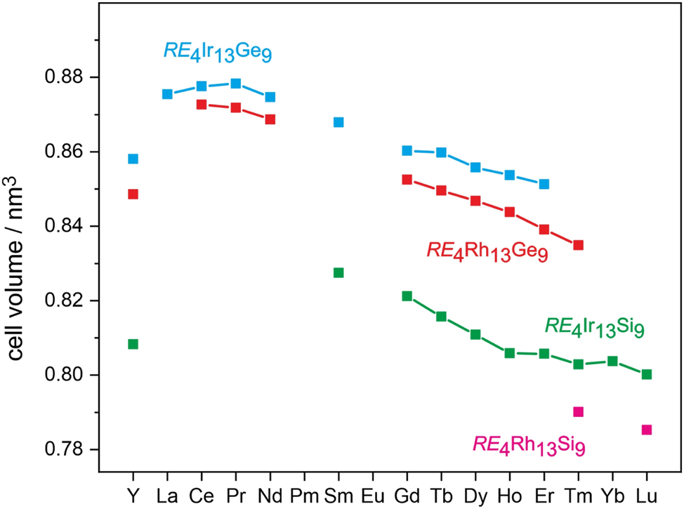
Plot of the cell volumes of the tetrelide series RE 4 T 13 X 9 (T = Rh, Ir and X = Si, Ge) with Ho4Ir13Ge9-type structure. The underlying lattice parameters are summarized in Table 1.
The structure of Gd4Ir13Ge9 was refined from single crystal X-ray diffractometer data and is discussed in the following. Although the Gd4Ir13Ge9 structure contains 17 crystallographically independent atomic sites and seems complex at first sight, it can easily be described by condensation of germanium centered trigonal prisms Ge@Gd4Ir2 and Ge@Gd2Ir4 (Figure 3). These prisms are condensed via common edges within the bc plane, forming a chain of condensed shamrocks 37 which extends in b direction. This building unit is inverted (due to many inversion centers of this centrosymmetric space group, e. g., 0, 0, 1/2 or 0, 1/2, 1/2), and, consequently, we obtain alternating strands of identical composition that are shifted with respect to each other by half the translation period a, emphasized by thin and thick lines in Figure 3.
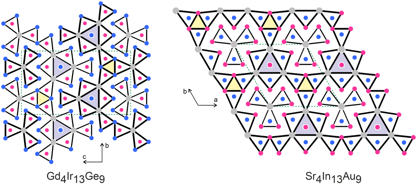
Projection of the Gd4Ir13Ge9 and Sr4In13Au9 structures along the short unit cell axes. Gadolinium (strontium), iridium (gold) and germanium (indium) atoms are drawn as medium grey, blue and magenta circles, respectively. All atoms lie on different mirror planes (x = 1/4 and 3/4 for Gd4Ir13Ge9 and z = 0 and 1/2 for Sr4In13Au9), accentuated by thin and thick lines. The trigonal prisms around the germanium (gold) atoms are emphasized. The empty Ir6 (In6) and filled Ir@Gd6 (In@Sr6) prisms are shaded.
The condensation of the Ge@Gd4Ir2 and Ge@Gd2Ir4 prisms leads to the formation of Ir84Ir32 and Gd24Gd32 trigonal prisms at the connection points of the shamrocks (shaded in Figure 3). The iridium-based trigonal prisms are too small to be occupied and thus remain empty. Those formed solely by gadolinium atoms are much larger and are filled with the Ir4 atoms. The Ir4 filled Gd24Gd32 trigonal prisms are the structural unit to be noted. These trigonal prisms seem to be too large for the Ir4 atoms and we observe a slightly enhanced U 11 displacement towards the triangular faces of prisms. This peculiar behavior is most likely a geometrical constraint induced by the prism condensation and a kind of compromise for the Gd4Ir13Ge9 structure. Many other metal-rich structures with related shamrock-like condensation patterns of trigonal prisms show similar displacements of the transition metal atoms with RE 6 trigonal prisms. Typical examples are isotypic Er4Ir13Si9 14 or the phosphides Ce13Ir34.4P24 38 and Y7Ir17P12. 39
The description of the Gd4Ir13Ge9 structure with a condensation pattern of trigonal prisms is a purely geometrical one, however, this motif of prism condensation helps to distinguish the many related structure types of metal-rich tetrelides and pnictides. Compilations of such structure types based on the prismatic motifs are given in several overviews. 2 , 3 , 4 , 5 , 6 , 7 , 8 , 9 , 10 , 11 , 40
The shortest interatomic distances in the Gd4Ir13Ge9 structure are found between the iridium and germanium atoms. The Ir–Ge distances range from 240 to 260 pm, comparable to the sum of the covalent radii 41 of 248 pm for Ir + Ge. Similar distances have been observed for CeIrGe 42 (256–275 pm Ir–Ge) and Ce9Ir37Ge25 43 (239–262 pm Ir–Ge). Each iridium atom in the Gd4Ir13Ge9 structure has between three and five germanium neighbors, and both atom types build up a three-dimensional [Ir13Ge9] δ− polyanionic network (Figure 4). The three crystallographically independent gadolinium atoms fill slightly distorted hexagonal prisms within the [Ir13Ge9] δ− network. The rectangular faces of the hexagonal prisms are all capped by iridium and gadolinium atoms at much longer Gd–Ir and Gd–Ge distances. The prisms filled by the Gd2 and Gd3 atoms form a trimeric unit. This leads to the Ir@Gd6 prism discussed above which shows the slightly enhanced displacement parameter U 11 for the Ir4 atoms.
![Figure 4:
Projection of the Gd4Ir13Ge9 structure onto the bc plane. Gadolinium, iridium and germanium atoms are drawn as medium grey, blue and magenta circles, respectively. The three-dimensional [Ir13Ge9] network is emphasized. Atom designations are given at the right-hand part of the drawing.](/document/doi/10.1515/znb-2025-0012/asset/graphic/j_znb-2025-0012_fig_004.jpg)
Projection of the Gd4Ir13Ge9 structure onto the bc plane. Gadolinium, iridium and germanium atoms are drawn as medium grey, blue and magenta circles, respectively. The three-dimensional [Ir13Ge9] network is emphasized. Atom designations are given at the right-hand part of the drawing.
The high iridium content in the Gd4Ir13Ge9 structure (50 at%) naturally leads to a variety of Ir–Ir interactions. The various Ir–Ir distances (except the isolated Ir4 atoms discussed above) range from 274–294 pm. The shorter ones are close to the Ir–Ir distance of 272 pm in fcc iridium. 44 This is the typical range in iridium-rich tetrelide and pnictide structures. Closely related structures are, e. g., Ce9Ir37Ge25 (275–294 pm Ir–Ir), 43 Lu3Ir7P5 (271–301 pm Ir–Ir) 45 or La5Ir19P12 (282–296 pm Ir–Ir). 46 Thus, the [Ir13Ge9] δ− network in Gd4Ir13Ge9 is stabilized by Ir–Ge and Ir–Ir bonding as well.
The germanium atoms are located within their Gd4Ir2 and Gd2Ir4 trigonal prisms and show no Ge–Ge bonding. As a consequence of the geometrical constraints of the Ge1@Gd2Ir4 and Ge4@Gd2Ir4 prism condensation forming the empty Ir6 prism (Figure 3), the Ge1 and Ge4 centers slightly move towards each other. Nevertheless, the resulting Ge1–Ge4 (291 pm) and Ge4–Ge4 (291 pm) distances are both significantly longer than the 245 pm Ge–Ge single bond distance in the diamond-type modification of germanium, 44 and are no bonding contacts.
Finally, we turn towards the known coloring variants of the Ho4Ir13Ge9-type 12 structure. Tables 1 and 2 list the known representatives of this structure type. In the family of tetrelides, examples are known with the transition metals rhodium and iridium and the tetrels silicon and germanium. A few pnictides have also been synthesized. The phosphides Sm4Rh13P9 and RE 4Ir13P9 (RE = Sm, Gd, Yb) as well as the arsenides Ca4Rh13As9, Sm4Rh13As9 and Eu4Ir13As9 are strictly isotypic with Ho4Ir13Ge9. Just the tetrel sites are substituted with the pnicogen atoms. This is different for the platinides Ce4Al13Pt9 26 and Sr4In13Pt9, 27 which are isopointal 47 , 48 but not isotypic. The more electronegative platinum atoms occupy the pnicogen sites and thus, this is another example for so-called anti-type structures. The most prominent example concerns the fluorite (CaF2) and anti-fluorite type (Li2O). This coloring principle is not that rare in the field of intermetallic compounds. Typical examples are the pairs Hf2Co4P3 49 versus Sr2In4Au3 50 or Eu5In9Pt7 27 versus Sc5Pt9Si7, 51 i.e., phosphide versus auride and platinide versus silicide character. The coloring in all these variants is driven by the course of the electronegativities.
A last topic concerns pnictides and an auride that exhibit the same stoichiometry but a different crystal structure. The silicide phosphides RE 4Co13(Si,P)9 (RE = Sm, Gd–Er) and U4Fe13P9 52 and the auride Sr4In13Au9 53 have a composition similar to Ho4Ir13Ge9, however, a different connectivity pattern of the trigonal prisms (Figure 3). First, the pair Ho4Ir13Ge9 versus Sr4In13Au9 is another example for an electronegativity driven anti-type, similar to the just discussed example. Second, the refined structures of Gd4Co13(Si,P)9 and Sr4In13Au9 show slightly enhanced U 33 displacements for the 1c sites (Co in Gd4Co13(Si,P)9 and In in Sr4In13Au9). Again, these atoms reside in Gd6 respectively Sr6 prisms that are formed as centers of the condensed shamrock unit, similar to Gd4Ir13Ge9, underpinning the close structural relationship.
5 Magnetic properties of Tb4Ir13Ge9
The temperature dependence of the magnetic susceptibility of Tb4Ir13Ge9 measured at 10 kOe is presented in Figure 5. Tb4Ir13Ge9 shows Curie-Weiss behavior above 25 K. A fit of the data (25–300 K range) with a modified Curie-Weiss law yielded an experimental magnetic moment of 10.4(1) µB Tb atom−1, a Weiss constant of −6.4(1) K and a temperature-independent contribution of χ 0 = −0.01390(7) emu mol−1. The experimentally derived moment is slightly larger than the free ion value of Tb3+ (9.72 µB). 54 Such slightly enhanced values have been observed for a variety of intermetallic terbium compounds. 55 The negative Weiss constant is indicative of antiferromagnetic interactions in the paramagnetic range.
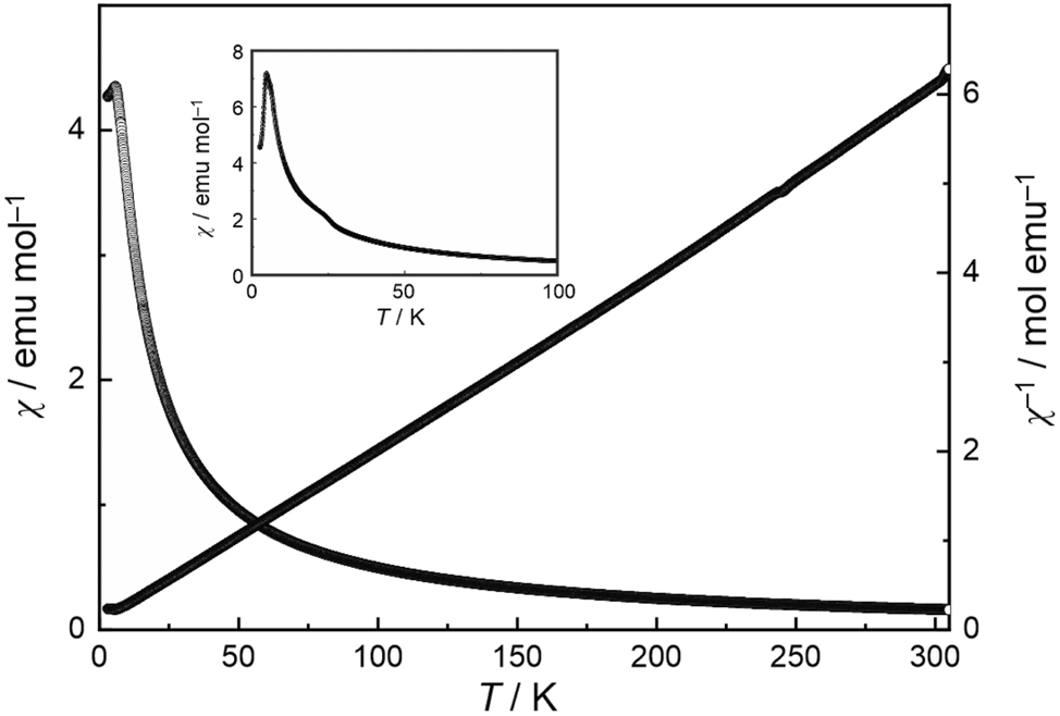
Temperature dependence of the magnetic susceptibility (χ and χ −1 values) of Tb4Ir13Ge9 measured at 10 kOe. The insert shows a 100 Oe measurement that clearly manifests the antiferromagnetic ordering.
The low-field measurement at 100 Oe (insert of Figure 5) clearly reveals antiferromagnetic ordering of the terbium magnetic moments below a Néel temperature of T N = 4.7(1) K, slightly higher than the one observed for the isotypic silicide Tb4Ir13Si9 (4.3 K). 14 The magnetization behavior is shown in Figure 6. At 50, 100 and 150 K, well above the magnetic ordering temperature, we observe a linear increase of the magnetization with increasing field strength as it is usual for a paramagnetic material. A first curvature occurs in the 10 K isotherm which is still above the Néel temperature. The 3 K isotherm in the magnetically ordered regime shows a two-step metamagnetic behavior (with negligible hysteresis) and thus underpins the antiferromagnetic ground state. The first (poorly pronounced) plateau is around a magnetization of ∼2 µB per Tb atom. The highest magnetization value at 3 K and 80 kOe of 5.61(1) µB per Tb atom is much lower than the theoretical saturation moment of 9 µB per Tb atom according to g J × J. 54 Keeping the three crystallographically independent terbium sites 2a, 4e and 2b in mind, it might be possible, that the first step of the 3 K isotherm corresponds to the antiparallel-to-parallel spin realignment of one of the two-fold sites. This magnetization behavior is similar to that observed for Tb4Ir13Si9. 14 A quantitative analyses of the terbium spin structure is only possible via neutron diffraction.
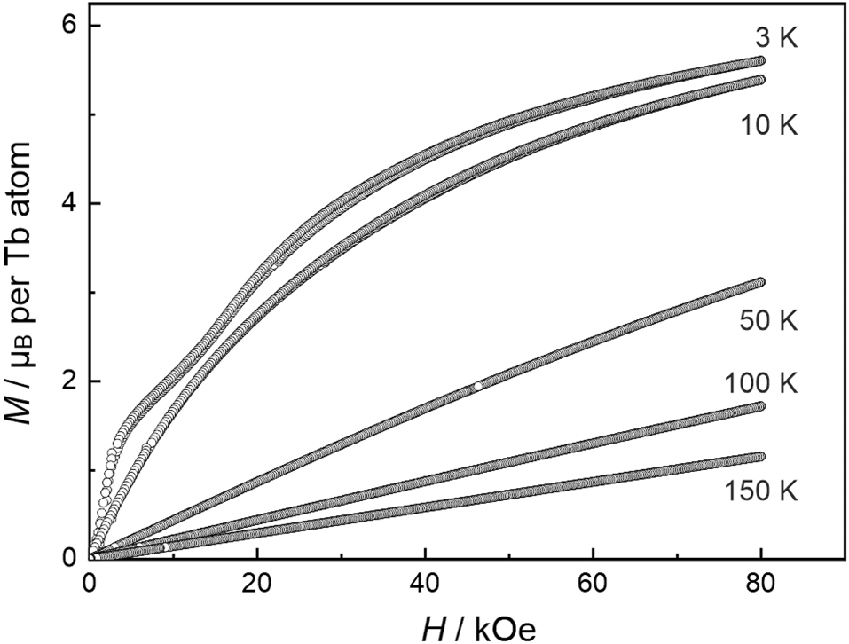
Magnetization isotherms of Tb4Ir13Ge9 measured at T = 3, 10, 50, 100 and 150 K.
Acknowledgements
We thank Dr. R.-D. Hoffmann for the intensity data collection.
-
Research ethics: Not applicable.
-
Informed consent: Not applicable.
-
Author contributions: All authors have accepted responsibility for the entire content of this submitted manuscript and approved the submission.
-
Use of Large Language Models, AI and Machine Learning Tools: Not relevant. Our group is able to think and act independently.
-
Conflict of interest statement: The authors declare no conflicts of interest regarding this article.
-
Research funding: This research was funded by Universität Münster and Deutsche Forschungsgemeinschaft (INST 211/1034-1).
-
Data availability: Data is available from the corresponding author on well-founded request.
References
1. Parthé, E.; Chabot, B.; Hovestreydt, E. Acta Crystallogr. B 1983, 39, 596–603.10.1107/S0108768183003031Suche in Google Scholar
2. Parthé, E.; Chabot, B. Crystal Structures and Crystal Chemistry of Ternary Rare Earth-Transition Metal Borides, Silicides and Homologues. In Handbook on the Physics and Chemistry of Rare Earths. Gschneidner, K. A.Jr., Eyring, L., Eds. Vol. 6; North-Holland: Amsterdam, 1984, pp. 113–332.10.1016/S0168-1273(84)06005-0Suche in Google Scholar
3. Parthé, E.; Hovestreydt, E. J. Less-Common Met. 1985, 110, 307–313.10.1016/0022-5088(85)90337-6Suche in Google Scholar
4. Madar, R.; Ghetta, V.; Dhahri, E.; Chaudouet, P.; Senateur, J. P. J. Solid State Chem. 1987, 66, 73–85; https://doi.org/10.1016/0022-4596(87)90222-2.Suche in Google Scholar
5. Pivan, J.-Y.; Guérin, R.; Sergent, M. J. Solid State Chem. 1987, 68, 11–21.10.1016/0022-4596(87)90279-9Suche in Google Scholar
6. Parthé, E.; Gelato, L.; Chabot, B.; Penzo, M.; Cenzual, K.; Gladyshevskii, R. TYPIX–Standardized Data and Crystal Chemical Characterization of Inorganic Structure Types. In Gmelin Handbook of Inorganic and Organometallic Chemistry, 8th ed.; Springer: Berlin, 1993.10.1007/978-3-662-02909-1Suche in Google Scholar
7. Kuz’ma, Y.; Chykhrij, S. Phosphides. In Handbook on the Physics and Chemistry of Rare Earths, Gschneidner, K. A.Jr., Eyring, L., Eds. Vol. 23, Elsevier Science: Amsterdam, 1996, chapter 156, pp. 285–433.10.1016/S0168-1273(96)23007-7Suche in Google Scholar
8. Prots’, Yu. M.; Jeitschko, W. Inorg. Chem. 1998, 37, 5431–5438.10.1021/ic980397wSuche in Google Scholar PubMed
9. Chykhrij, S. I. Pol. J. Chem. 1999, 73, 1595–1611.Suche in Google Scholar
10. Le Sénéchal, C.; Babizhetsky, V. S.; Députier, S.; Pivan, J.-Y.; Guérin, R. Z. Anorg. Allg. Chem. 2001, 627, 1325–1333.10.1002/1521-3749(200106)627:6<1325::AID-ZAAC1325>3.0.CO;2-FSuche in Google Scholar
11. Pöttgen, R.; Hönle, W.; von Schnering, H. G. Phosphides: Solid State Chemistry. In Encyclopedia of Inorganic Chemistry, King, R. B., Ed. Vol. VII, 2nd ed., Wiley: New York, 2005, pp. 4255–4308.10.1002/0470862106.ia184Suche in Google Scholar
12. Sologub, O. L.; Prots, Yu. M.; Salamakha, P. S.; Pecharsky, V. K.; Bodak, O. I. J. Alloys Compd. 1993, 202, 13–15; https://doi.org/10.1016/0925-8388(93)90509-l.Suche in Google Scholar
13. Salamakha, P. S.; Sologub, O. L. J. Alloys Compd. 1999, 287, L1–L3; https://doi.org/10.1016/s0925-8388(98)01054-8.Suche in Google Scholar
14. Vernière, A.; Lejay, P.; Bordet, P.; Chenavas, J.; Tholence, J. L.; Boucherle, J. X.; Keller, N. J. Alloys Compd. 1995, 218, 197–203.10.1016/0925-8388(94)01400-0Suche in Google Scholar
15. Yarema, M.; Zaremba, O.; Hlukhyy, V.; Fässler, T.; Gladyshevskii, R. Xth Intern. Conf. Crystal Chem. Intermetallic Compd., Lviv, September 17–20, 2007, P103.Suche in Google Scholar
16. Yarema, M.; Zaremba, O.; Gladyshevskii, R.; Hlukhyy, V.; Fässler, T. F. J. Solid State Chem. 2012, 196, 72–78; https://doi.org/10.1016/j.jssc.2012.07.055.Suche in Google Scholar
17. Pikul, A. P.; Kaczorowski, D. J. Phys. Chem. Solids 2008, 69, 2841–2844; https://doi.org/10.1016/j.jpcs.2008.07.010.Suche in Google Scholar
18. Voßwinkel, D.; Niehaus, O.; Rodewald, U. C.; Pöttgen, R. Z. Naturforsch. 2012, 67b, 1241–1247.10.5560/znb.2012-0265Suche in Google Scholar
19. Voßwinkel, D.; Niehaus, O.; Pöttgen, R. Z. Anorg. Allg. Chem. 2013, 639, 2623–2630.10.1002/zaac.201300369Suche in Google Scholar
20. Voßwinkel, D.; Niehaus, O.; Gerke, B.; Benndorf, C.; Eckert, H.; Pöttgen, R. Z. Anorg. Allg. Chem. 2015, 641, 238–246.10.1002/zaac.201400458Suche in Google Scholar
21. Voßwinkel, D.; Matar, S. F.; Pöttgen, R. Monatsh. Chem. 2015, 146, 1375–1383; https://doi.org/10.1007/s00706-015-1525-5.Suche in Google Scholar
22. Voßwinkel, D.; Benndorf, C.; Eckert, H.; Matar, S. F.; Pöttgen, R. Z. Kristallogr. 2016, 231, 475–486.10.1515/zkri-2016-1957Suche in Google Scholar
23. Voßwinkel, D.; Pöttgen, R. Z. Naturforsch. 2017, 72b, 775–780.10.1515/znb-2017-0073Suche in Google Scholar
24. Pfannenschmidt, U. Neue übergangsmetallreiche Phosphide und Arsenide der Seltenerdelemente. Dissertation; Universität Münster: Münster, 2011.Suche in Google Scholar
25. Wurth, A.; Keimes, V.; Johrendt, D.; Mewis, A. Z. Anorg. Allg. Chem. 2001, 627, 2183–2190; https://doi.org/10.1002/1521-3749(200109)627:9<2183::aid-zaac2183>3.0.co;2-j.10.1002/1521-3749(200109)627:9<2183::AID-ZAAC2183>3.0.CO;2-JSuche in Google Scholar
26. Morozova, Y.; Gribanov, A.; Murashova, E.; Dunaev, S.; Grytsiv, A.; Rogl, P.; Giester, G.; Kaczorowski, D. J. Alloys Compd. 2018, 767, 496–503; https://doi.org/10.1016/j.jallcom.2018.07.146.Suche in Google Scholar
27. Heying, B.; Kösters, J.; Heletta, L.; Klenner, S.; Pöttgen, R. Monatsh. Chem. 2019, 150, 1163–1173.10.1007/s00706-019-02412-8Suche in Google Scholar
28. Pöttgen, R.; Gulden, Th.; Simon, A. GIT Labor-Fachz. 1999, 43, 133–136.Suche in Google Scholar
29. Kanatzidis, M. G.; Pöttgen, R.; Jeitschko, W. Angew. Chem. Int. Ed. 2005, 44, 6996–7023; https://doi.org/10.1002/anie.200462170.Suche in Google Scholar
30. Pöttgen, R. Z. Kristallogr. 2025, 240, 127–139. https://doi.org/10.1515/zkri-2025-0006.Suche in Google Scholar
31. Yvon, K.; Jeitschko, W.; Parthé, E. J. Appl. Crystallogr. 1977, 10, 73–74.10.1107/S0021889877012898Suche in Google Scholar
32. OriginPro 2024 (version 10.1.0.170), OriginLab Corporation: Nothhampton, Massachusetts (USA), 2024.Suche in Google Scholar
33. CorelDRAW Graphics Suite 2017 (version 19.0.0.328), Corel Corporation: Ottawa, Ontario (Canada), 2017.Suche in Google Scholar
34. Villars, P.; Cenzual, K.; Eds. Pearson’s Crystal Data: Crystal Structure Database for Inorganic Compounds (release 2023/24); ASM International®: Materials Park: Ohio (USA), 2023.Suche in Google Scholar
35. Petříček, V.; Dušek, M.; Palatinus, L. Z. Kristallogr. 2014, 229, 345–352.10.1515/zkri-2014-1737Suche in Google Scholar
36. Petříček, V.; Palatinus, L.; Plášil, J.; Dušek, M. Z. Kristallogr. 2023, 238, 271–282.10.1515/zkri-2023-0005Suche in Google Scholar
37. Zaremba, N.; Krnel, M.; Prots, Y.; König, M.; Akselrud, L.; Grin, Y.; Svanidze, E. Inorg. Chem. 2024, 63, 4566–4573; https://doi.org/10.1021/acs.inorgchem.3c03837.Suche in Google Scholar
38. Pfannenschmidt, U.; Rodewald, U.Ch.; Pöttgen, R. Z. Kristallogr. 2011, 226, 229–235.10.1524/zkri.2011.1355Suche in Google Scholar
39. Pfannenschmidt, U.; Pöttgen, R. Intermetallics 2011, 19, 1052–1058.10.1016/j.intermet.2011.03.016Suche in Google Scholar
40. Gladyshevskii, E. I.; Grin’, Y. N. Sov. Phys. Crystallogr. 1981, 26, 683–689.Suche in Google Scholar
41. Emsley, J. The Elements; Oxford University Press: Oxford, 1999.Suche in Google Scholar
42. Voßwinkel, D.; Block, T.; Pöttgen, R. Z. Kristallogr. NCS 2025, 240; https://doi.org/10.1515/ncrs-2025-0068.Suche in Google Scholar
43. Gaudin, E.; Chevalier, B.; Heying, B.; Rodewald, U. C.; Pöttgen, R. Chem. Mater. 2005, 17, 2693–2700; https://doi.org/10.1021/cm040203c.Suche in Google Scholar
44. Donohue, J. The Structures of the Elements; Wiley: New York, 1974.Suche in Google Scholar
45. Pfannenschmidt, U.; Rodewald, U. C.; Pöttgen, R. Z. Anorg. Allg. Chem. 2010, 636, 314–319.10.1002/zaac.200900331Suche in Google Scholar
46. Pfannenschmidt, U.; Rodewald, U. C.; Hoffmann, R.-D.; Pöttgen, R. J. Solid State Chem. 2011, 184, 2731–2737; https://doi.org/10.1016/j.jssc.2011.07.045.Suche in Google Scholar
47. Gelato, L. M.; Parthé, E. J. Appl. Crystallogr. 1987, 20, 139–143.10.1107/S0021889887086965Suche in Google Scholar
48. Parthé, E.; Gelato, L. M. Acta Crystallogr. 1984, A40, 169–183.10.1107/S0108767384000416Suche in Google Scholar
49. Ganglberger, E. Monatsh. Chem. 1968, 99, 566–574; https://doi.org/10.1007/bf00901205.Suche in Google Scholar
50. Hoffmann, R.-D.; Pöttgen, R.; Rosenhahn, C.; Mosel, B. D.; Künnen, B.; Kotzyba, G. J. Solid State Chem. 1999, 145, 283–290.10.1006/jssc.1999.8265Suche in Google Scholar
51. Lorenz, P.; Jung, W. Z. Anorg. Allg. Chem. 2009, 635, 920–925; https://doi.org/10.1002/zaac.200900101.Suche in Google Scholar
52. Jeitschko, W.; Jakubowski-Ripke, U.; Albering, J. Z. Anorg. Allg. Chem. 2011, 637, 895–900.10.1002/zaac.201000404Suche in Google Scholar
53. Palasyuk, A.; Dai, J.-C.; Corbett, J. D. Inorg. Chem. 2008, 47, 3128–3134; https://doi.org/10.1021/ic702145y.Suche in Google Scholar PubMed
54. Lueken, H. Magnetochemie; Teubner: Stuttgart, 1999.10.1007/978-3-322-80118-0Suche in Google Scholar
55. Szytuła, A.; Leciejewicz, J. Handbook of Crystal Structures and Magnetic Properties of Rare Earth Intermetallics; CRC Press: Boca Raton, 1994.Suche in Google Scholar
© 2025 Walter de Gruyter GmbH, Berlin/Boston
Artikel in diesem Heft
- Frontmatter
- In this issue
- Research Articles
- Chemical aspects of the preparation of Vulcanised Fibre using zinc chloride hydrates: from a brief history to a new consideration of the key reactions in ionic liquids
- On the preparation and spectral properties of some hydroxy-substituted triphenylmethane dyes
- High-pressure synthesis and crystal structure of Ga5Na1–x B12O26–x (OH) x (x = 0.12)
- Intermetallic phases with Ho4Ir13Ge9-type structure
- Interplay between oxidative addition and reductive elimination at a diruthenium complex bearing the bis(diphenylphosphanyl)amine ligand
- Anthracene-d- and l-phenylalanine derivatives: synthesis, dual-state emission, mechanochromic luminescence, chiroptical property and enantioselective recognition of free amino acids
- Synthesis, structures and optical properties of 3,3′-disubstituted biphenyl compounds