Synthesis, structures and optical properties of 3,3′-disubstituted biphenyl compounds
-
Shuli Gao
 ,
Yong Nie
and
Meng Li
,
Yong Nie
and
Meng Li

Abstract
The bromination of the electron-deficient 2,2′-dicyano-6,6′-difluorobiphenyl with elemental bromine in HNO3/H2SO4 produces mainly 3,3′-dibromobiphenyl (1) and 3-nitro-3′-bromobiphenyl (2) in a total yield of 70 %. Compound 1 reacts with carbazole to yield the 3,3′-dibromo-6,6′-di(9H-carbazol-9-yl)-[1,1′-biphenyl]-2,2′-dicarbonitrile (6). The structures of the products have been studied by spectroscopic methods and X-ray diffraction, as well as DFT calculations. The optical properties of some of the compounds have been investigated by UV/Vis or fluorescene spectrocopy, which show that compound 6 has Thermally Activated Delayed Fluorescence (TADF) and Aggregation-Induced Emission (AIE) properties (i.e. Aggregation-Induced Delayed Fluorescence, AIDF). These biphenyl products may find potential applications in the field of organic photofunctional materials.
1 Introduction
Organic photoluminescent materials have gained much attention due to their applications in displays and lighting research and development. As a new generation of emitting materials for organic light emitting diodes (OLEDs), Thermally Activated Delayed Fluorescence (TADF) materials have been receiving increasing attention because of their excellent exciton utilization. 1 , 2 Among the many types of small molecule TADF materials, the biphenyl system stands out with their great potential to afford materials and devices with excellent photoluminescent and electroluminescent efficiencies, including the axially chiral ones with circularly polarized luminescence properties. 3 One of us 4 , 5 , 6 , 7 , 8 , 9 and other groups 10 , 11 have been actively studying the related systems starting from the 4,4′-dibromo- or -difluorobiphenyl compounds (Figure 1) followed by various further derivatizations. Despite some progress made, other substitution positions on the biphenyl skeleton definitely merit further investigation, for which the halogenated biphenyl species are generally needed.

Chemical structures of several electron-deficient 2,2′-dicyanobiphenyl systems including 4,4′-dibromobiphenyl compounds C and D.
The electrophilic halogenation reactions (especially bromination reactions) of aromatics are well-defined reaction types and the selectivity has been well studied for electron-rich aromatics, however, there has been much less study on the electron-deficient aromatic systems, and the reaction conditions are clearly different from those of the electron-rich aromatics. 12 Compared with the mono(hetero)aromatic rings, 13 , 14 the bromination reactions of biphenyl-type compounds have been relatively less studied, and the bromination reactions of the electron-deficient biphenyl systems have been even less studied. 15 , 16 , 17 , 18 , 19 In recent study of the axially chiral optoelectronic materials and devices by Chen 4 , 5 , 6 , 7 , 8 , 9 and Zheng 10 , 11 et al. the electron-deficient 2,2′-dicyanobiphenyl system (Figure 1) has been involved. Among them, 4,4′-dibromobiphenyl (C) (a formally brominated derivative of compound A) is an important intermediate, which reacts with carbazole derivatives to generate compound D 5 with TADF properties (similar reaction of compound A with carbazole gives analogous compound B) and the transformation of the C–Br bond in compound D through metal-catalyzed coupling reactions can generate a series of compounds with remarkable TADF properties, 4 , 5 , 6 , 7 but an important factor limiting the further development of this system is the relatively complicated synthesis of 4,4′-dibromobiphenyl (C), which requires a multi-step reaction process and suffers from low yields. 7 , 20
On the other hand, traditional organic luminescent materials emit strongly in solutions but tend to quench in aggregate or solid state (the so-called Aggregation-Caused Quenching Effect), but another type of Aggregation-Induced Eemission (AIE) materials show the opposite emission property that they emit strongly in aggregate or solid state which have gained much current attention and have demonstrated very broad applications in various fields. 21 , 22 Therefore, it is also of interest to study the possible AIE-related property in these biphenyl compounds. In this respect, the related biphenyl system with Aggregation-Induced Delayed Fluorescence (AIDF), 23 , 24 i.e. combining both AIE and TADF properties, has not been reported.
We envisioned that utilizing the readily available electron-deficient biphenyl compound A to directly generate the brominated biphenyl product C through bromination reaction and other related compounds by further transformation, which can accelerate the study of biphenyl TADF materials. To this end, we have investigated the bromination reactions of compound A with elemental bromine. The results show that the bromination fails to produce the expected 4,4′-dibromobiphenyl compound C. Instead, 3,3′-dibromobiphenyl 1, 3-nitro-3′-bromobiphenyl 2, and 3,3′,4,4′-tetrabromobiphenyl 3 are obtained, as well as a small amount of polybrominated products 4 and 5 (Figure 2). Compound 1 can be transformed into the biscarbazolyl derivative 6 which displays AIDF properties. In this paper, in order to study the substitution effect, we report on the synthesis, structures and optical properties of compounds 1–3 and compound 6.
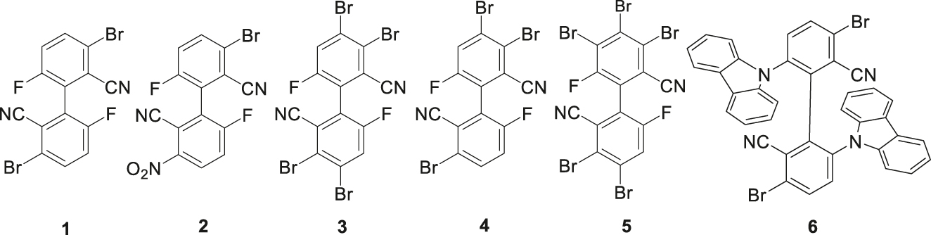
Chemical structures of bromobiphenyl products in this work.
2 Experimental section
2.1 Instruments and reagents
IR spectra were recorded in the range 450–4,000 cm−1 on a Perkin Elmer Tensor II spectrometer using KBr pellets. 1H and 13C NMR analyses were performed using a Bruker Avance III 600 MHz spectrometer. As internal references for 1H and 13C NMR spectroscopy the signals of CDCl3 were used and calculated relative to tetramethylsilane (TMS). Melting points were measured with a SGW X-4 apparatus and were not corrected. The high resolution mass spectra were measured with a Thermo Fisher Scientific LTQ FTICR-MS instrument (DART positive ion mode or ESI positive, or AP MALDI ion mode). UV/Vis spectra were recorded using a UV-9000S Plus spectrometer. Fluorescence was measured on Edinburgh FLS920 and FLS1000 spectrometers and absolute quantum yield was tested using a barium sulfate integrating sphere. GC-MS was measured on a GCMS-QP2020 coupled with SH-RXi-5SilMS capillary column. The solvents were commercially available and used without further purification.
2.2 Synthesis of bromobiphenyl compounds
The starting material 6,6′-difluoro-[1,1′-biphenyl]-2,2′-dicarbonitrile (compound A) was synthesized according to the literature methods. 9 , 11
2.2.1 Synthesis of 3,3′-dibromo-6,6′-difluoro-[1,1′-biphenyl]-2,2′-dicarbonitrile (1) and 3-bromo-6,6′-difluoro-3′-nitro-[1,1′-biphenyl]-2,2′-dicarbonitrile (2)
Reaction using 1 equiv. of bromine: In a reaction flask, compound A (3.5 g, 14.5 mmol), elemental bromine (774 μL, 14.5 mmol) and 9.1 mL of concentrated nitric acid were added. It was cooled with an ice-water bath and 18.2 mL of concentrated sulfuric acid was added dropwise to form a reddish-brown solution. The ice-water bath was removed and the reaction mixture was heated in an oil bath to 80 °C for 3 h. The resulting yellow solution was cooled with an ice-water bath and diluted with 10 mL of water and neutralized with sodium bicarbonate solution to pH > 8. The mixture was separated and the water phase was extracted with ethyl acetate (20 mL × 3). The organic phases were combined, washed with brine, dried with anhydrous Na2SO4, concentrated, and separated by column chromatography (eluent dichloromethane: petroleum ether (b.p. 60–90 °C) = 1:1, v/v) to afford compounds 1 and 2.
Compound 1: Colorless powder (2.39 g, yield 41.4 %); R f = 0.50 (dichloromethane: petroleum ether = 1:1, v/v); m.p. 201.3–202.5 °C. – UV/Vis (THF): λ max (lg ε max) = 225 nm (4.64), 303 nm (4.08). – IR (KBr) ν = 2,926, 2,361, 2,239, 1,632, 1,439, 1,254, 833 cm-1. – 1H NMR (600 MHz, CDCl3, 25 °C, TMS): δ = 7.83 (dd, J = 9.0, 4.3 Hz, 2H), 7.40 (t, J = 8.5 Hz, 2H). – 13C NMR (151 MHz, CDCl3): δ = 159.37, 157.69, 136.33, 136.27, 124.88, 124.74, 122.29, 122.14, 121.47, 121.45, 114.40. – GC-MS: m/z = 398 [M]+. – HRMS (DART): m/z = 396.8781 (calcd. 396.8782 for C14H5N2Br2F2, [M+H]+).
Compound 2: Colorless powder (1.52 g, yield 28.8 %); R f = 0.22 (dichloromethane: petroleum ether = 1:1, v/v); m.p. 191.8–192.5 °C. – UV/Vis (THF): λ max (lg ε max) = 227 nm (4.68), 302 nm (3.95). – IR (KBr) ν = 2,924, 1,537, 1,348, 1,273, 833 cm–1. – 1H NMR (600 MHz, CDCl3, 25 °C, TMS): δ = 8.56 (dd, J = 9.3, 4.6 Hz, 1H), 7.90 (dd, J = 9.0, 4.7 Hz, 1H), 7.71 (dd, J = 9.3, 7.4 Hz, 1H), 7.45 (t, J = 8.6 Hz, 1H). – 13C NMR (151 MHz, CDCl3): δ = 163.15, 161.41, 159.30, 136.87, 129.37, 126.17, 122.38, 122.23, 121.41, 121.26, 114.14, 111.67. – GC-MS: m/z = 363 [M]+. – HRMS ((+)-ESI): m/z = 385.9345 (calcd. 385.9347 for C14H4O3N3BrF2Na, [M+Na]+).
Reaction using 1.5 equiv. of bromine: Same procedures as those for the reaction using 1 equiv. of Br2, compound A (360.0 mg, 1.5 mmol), elemental bromine (115.5 μL, 2.25 mmol), 1.4 mL of concentrated nitric acid and 2.8 mL of concentrated sulfuric acid. Compounds 1 (163.1 mg, yield 27 %) and 2 (55.2 mg, yield 10 %) were obtained.
2.2.2 Synthesis of 3,3′,4,4′-tetrabromo-6,6′-difluoro-[1,1′-biphenyl]-2,2′-dicarbonitrile (3)
Same procedures as those for the reaction using 1 equiv. of Br2, compound A (360.0 mg, 1.5 mmol), elemental bromine (153.7 μL, 3.0 mmol), 1.8 mL of concentrated nitric acid and 3.6 mL of concentrated sulfuric acid. Compounds 1 (120 mg, yield 20 %) and 3 were isolated.
Compound 3: Colorless powder (80 mg, yield 10 %); R f = 0.61 (dichloromethane: petroleum ether = 1:1, v/v); m.p. 204.3–205.4 °C. – UV/Vis (THF): λ max (lg ε max) = 228 nm (4.71), 314 nm (4.08). – IR (KBr): ν = 2,926, 1,572, 1,408, 1,371, 1,227, 874 cm–1. – 1H NMR (600 MHz, CDCl3, 25 °C, TMS): δ = 7.82 (d, J = 7.9 Hz, 2H). – 13C NMR (151 MHz, CDCl3): δ = 158.59, 129.76, 126.12, 125.95, 125.04, 123.41, 119.14, 114.30. – GC-MS: m/z = 556 [M]+. – HRMS (DART): m/z = 569.7257 (calcd. 569.7258 for C14H6N3Br4F2, [M + NH4]+).
2.2.3 Synthesis of 3,3′,4-tribromo-6,6′-difluoro-[1,1′-biphenyl]-2,2′-dicarbonitrile (4) and 3,3′,4,4′,5-pentabromo-6,6′-difluoro-[1,1′-biphenyl]-2,2′-dicarbonitrile (5)
Same procedures as those for reaction using 1 equiv. of Br2, compound A (360.0 mg, 1.5 mmol), elemental bromine (231 μL, 4.5 mmol), 2.7 mL of concentrated nitric acid, 5.4 mL of concentrated sulfuric acid. Compound 3 (yield 10 %) and a very small amount of a white powder were obtained. Based on the results of GC-MS (m/z = 476, 633) and the above mentioned bromination reactions, the white powder was assigned to be a mixture of compounds 4 and 5, which were difficult to separate.
2.2.4 Synthesis of compounds 6–8
Under argon, to a Schlenk tube was added carbazole (60.2 mg, 0.36 mmol), NaH (60 % dispersion in mineral oil, 14.4 mg, 0.36 mmol) and 5 mL of anhydrous DMF, and the grey slurry was stirred for 0.5 h before a solution of compound 1 (60.0 mg, 0.15 mmol) in 3 mL of anhydrous DMF was added. The resulting mixture was heated at 80 °C (oil bath) for 12 h, and after cooling to room temperature the mixture was pored to 15 mL of water. After extraction with ethyl acetate (20 mL × 3), the organic phases were dried with anhydrous sodium sulfate and after filtration the filtrate was concentrated and separated by column chromatography (eluent dichloromethane: petroleum ether = 1:1, v/v) to afford compound 6. A very small amount of a yellow green solid was obtained which was identified by mass spectrometry as compounds 7 and 8 which were inseparable.
Compound 6: Yellow green powder (46.4 mg, yield 44.7 %); R f = 0.48 (dichloromethane: petroleum ether = 1:1, v/v); m.p. 243.4–244.0 °C; – UV/Vis (THF): λ max (lg ε max) = 287 nm (4.80), 330 nm (4.43). – IR (KBr): ν = 2,928, 1,454, 1,225, 746, 723 cm–1 . – 1H NMR (600 MHz, CDCl3, 25 °C, TMS): δ = 7.95 (d, J = 7.6 Hz, 2H), 7.69 (t, J = 9.3 Hz, 4H), 7.36 (t, J = 7.6 Hz, 2H), 7.24 (m, J = 7.4 Hz, 2H), 7.19 (m, J = 8.0, 3.8 Hz, 4H), 6.87 (t, J = 7.4 Hz, 2H), 6.48 (t, J = 7.6 Hz, 2H), 5.47 (d, J = 8.1 Hz, 2H). – 13C NMR (151 MHz, CDCl3): δ = 141.18, 139.97, 138.57, 137.43, 135.53, 135.12, 126.22, 125.83, 123.99, 120.88, 120.41, 119.38, 116.54, 109.38, 109.08, 77.23, 77.02, 76.81. – HRMS (AP-MALDI): m/z = 690.0048 (calcd. 690.0049 for C38H20N4Br2, [M]+).
Compound 7: HRMS ((+)-ESI): m/z = 565.9273 (calcd. 565.9274 for C26H12N3Br2FNa, [M+Na]+).
Compound 8: HRMS (AP-MALDI): m/z = 778.1597 (calcd. 778.1601 for C50H29N5Br, [M]+).
3 Results and discussion
3.1 Bromination reaction of compound A
The reactions of compound A with elemental bromine in mixed acids are shown in Scheme 1. In this process, nitric acid acts as an oxidizing agent with sulfuric acid to generate an intermediate and interacts with Br2 to form the Br+ HSO4 − complex 12 to react with compound A. In the reaction using 1 equivalent of bromine, the reaction occurs first at the position next to the cyano group (i.e. 3,3′-position) to produce the dibromobiphenyl 1, which is in agreement with the results of Mulliken’s charge distribution computed at the B3LYP/6-311 + G(d,p) level of theory by using the density-functional theory (DFT) method, 25 but not consistent with the results at the B3LYP/6-31G(d,p) level (Figure 3), which suggests the basis set dependence in such calculations. In addition, the reaction produces 3 with a nitro group on the other benzene ring, which results from the competing reactions of bromination and nitration under these conditions. 12 , 18 The total yields of the main products 1 and 2 reach 70 %.
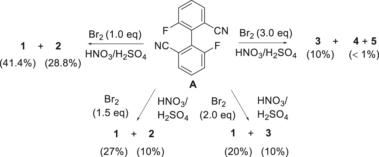
Bromination of biphenyl compound A with Br2 (isolated yields are in parentheses).
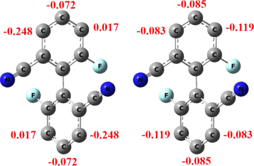
Mulliken charges of some ring carbon atoms of compound A (left: B3LYP/6-311 + G(d,p) level; right: B3LYP/6-31G(d,p) level).
When the amount of bromine is increased to 1.5 equivalents, the yield of product 1 is lower. When the amount of bromine is increased to two equivalents, the yield of the dibromo product 1 is only 20 %, but the nitration product 2 is not separated, and a small amount of the tetrabromo product 3 is obtained. When the amount of bromine is further increased to three equivalents, no product 1 was obtained, and product 3 is produced in a yield of 10 %, and a very small amount of the polybrominated products 4 and 5 is formed, and the latter two products are difficult to separate, and insoluble in common organic solvents.
The above results of the bromination of compound A with elemental bromine show that the optimal amount of bromine is 1 equiv., and the main products are the dibromo compound 1 and bromo/nitro product 2 with functionization at the 3,3′-positions. With more than two equiv. of bromine, the bromination occurs at the 4- or 4,4′-position(s) with the corresponding products in much lower yields.
3.2 Synthesis of carbazolyl biphenyls from compound 1
When compound 1 is reacted with carbazole in the presence of a base such as NaH, the biscarbazolyl product 3,3′-dibromo-6,6′-di(9H-carbazol-9-yl)-[1,1′-biphenyl]-2,2′-dicarbonitrile (6) is obtained in 45 % yield, together with a small amount of the monocarbazolyl product 7 and triscarbazolyl compound 8 (Scheme 2). Compounds 7 and 8 are difficult to separate and were characterized by high resolution mass spectrometry. The substitution of a bromine atom by a carbazolyl group in the formation of compound 8, via an aromatic nuleophilic substitution (SNAr) reaction, is due to the obvious electron deficiency of the benzene ring in the starting compound 1, and is a relatively rare example of metal catalyst-free C–N coupling reaction. 26
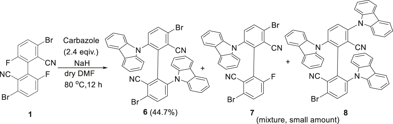
Reaction of 1 with carbazole (isolated yields are in parentheses).
3.3 Crystal structures of compounds 1–3 and 6
The major brominated biphenyl products 1–3 and the biscarbazolyl compound 6 were structurally characterized by infrared, 1H NMR, 13C NMR spectroscopy, and high-resolution mass spectrometry. Single crystals of compounds 1–3 and 6 could be obtained and their crystal structures were determined by X-ray diffraction, the details of which can be found in the Supporting Information available online.
Single crystals of compound 1 were obtained by slow evaporation of an ethyl acetate solution. Compound 1 crystallizes in the monoclinic space group C2/c with Z = 4. Selected bond lengths, bond angles and torsion angles are summarized in the Supporting information. The C–C bond length between the two benzene rings is 1.488(5) Å, similar to those in the above-mentioned biphenyls (1.488(5)−1.502(5) Å). 5 , 7 , 9 , 10 , 11 The C–Br and C–F bond lengths are 1.881(3) Å and 1.341(3) Å, respectively. The dihedral angle of the two benzene rings of the biphenyl framework is 63.48° (Figure 4). Intermolecular C–H⋯F (H(4)⋯F(1) 2.572 Å) and C–H⋯N (H(5)⋯N(1) 2.717 Å) hydrogen bonding interactions are present in crystals of compound 1 (Figure 5).
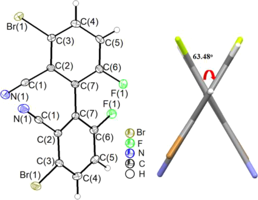
Molecular structure of compound 1 (left; displacement ellipsoids are drawn at the 30 % probability level, H atoms as spheres with arbitrary radii) and dihedral angle of the biphenyl (right). Note that the entire molecule has crystallographic 2 (C 2) symmetry, the two-fold axis bisecting the C(7)–C(7) bond and lying approximately in the paper plane.
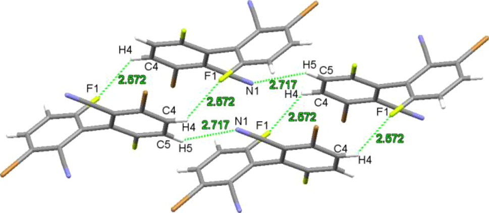
Weak intermolecular interactions in crystals of compound 1.
Single crystals of compound 2 were grown from an ethyl acetate solution. The compound crystallizes in the monoclinic space group P21/c with Z = 4. Due to the problem of the crystal quality, a discrepancy factor R1 of 0.1489 was obtained in the refinement. Therefore, the bond lengths and angles will not be discussed here. The molecular structure is shown in Figure 6 (left). The dihedral angle of its biphenyl framework is 113.25° (Figure 6, right). Weak C–H⋯O (H(5)⋯O(2) 2.684 Å) hydrogen bonding and C–F⋯π halogen bonding 16 , 27 (F···centroid distance of 3.688 Å) interactions are present in the crystals of compound 2 (Figure 7).
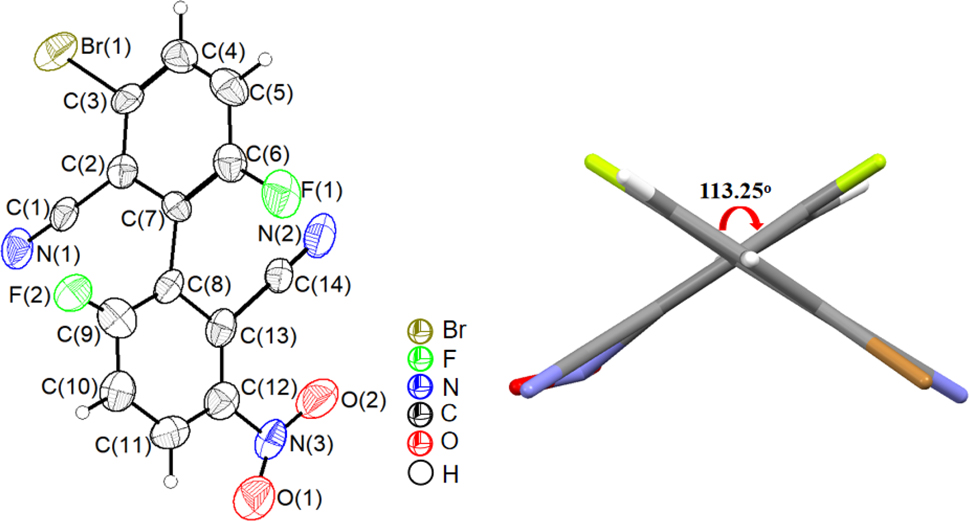
Molecular structure of compound 2 (left; displacement ellipsoids are drawn at the 30 % probability level, H atoms as spheres with arbitrary radii) and dihedral angle of the biphenyl (right).
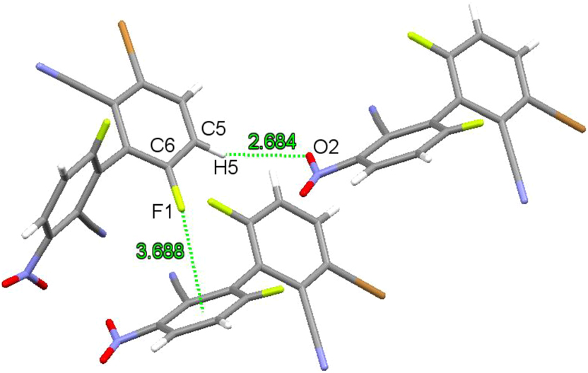
Weak intermolecular interactions in crystals of compound 2.
Single crystals of compound 3 were also obtained by the same method as that for 1. Compound 3 crystallizes in the monoclinic space group P21/c with Z = 8. In the crystal structure (Figure 8), there are two crystallographically independent molecules 3A and 3B. The C–C bond lengths between the benzene rings of the two molecules are 1.499(10) Å (C7–C8) and 1.500(10) Å (C21–C22), respectively, which are essentially the same as that in compound 1, indicating that the number of bromine atoms has no significant effect on the C–C bond length of the biphenyl. In molecule 3A, the C–Br bond lengths are 1.859(8) Å–1.891(8) Å and the C–F bond lengths are 1.340(9) Å (C1–F1) and 1.338(8) Å (C9–F2), respectively. In molecule 3B, the corresponding bond lengths are 1.864(8) Å–1.895(8) Å (C–Br), and 1.339(9) Å (C20–F3) and 1.318(9) Å (C23–F4), respectively. The halogen-related bond lengths are essentially the same in the two molecules, and those in compound 1. Quite interestingly, in the biphenyl framework, the dihedral angles of the biphenyl are 61.23° (Cg1 (C16–C17–C18)/Cg2 (C22–C23–C24) and 116.03° (Cg3 (C1–C2–C3)/Cg4 (C8–C9–C10), respectively, for the two independent molecules (Figure 8, right). Note that the noticeably different dihedral angles imply grossly different F⋯F and (CN)⋯(CN) intramolecular distances or, in other words, they are not just the complementary dihedral angles which in one molecule add to 180°.
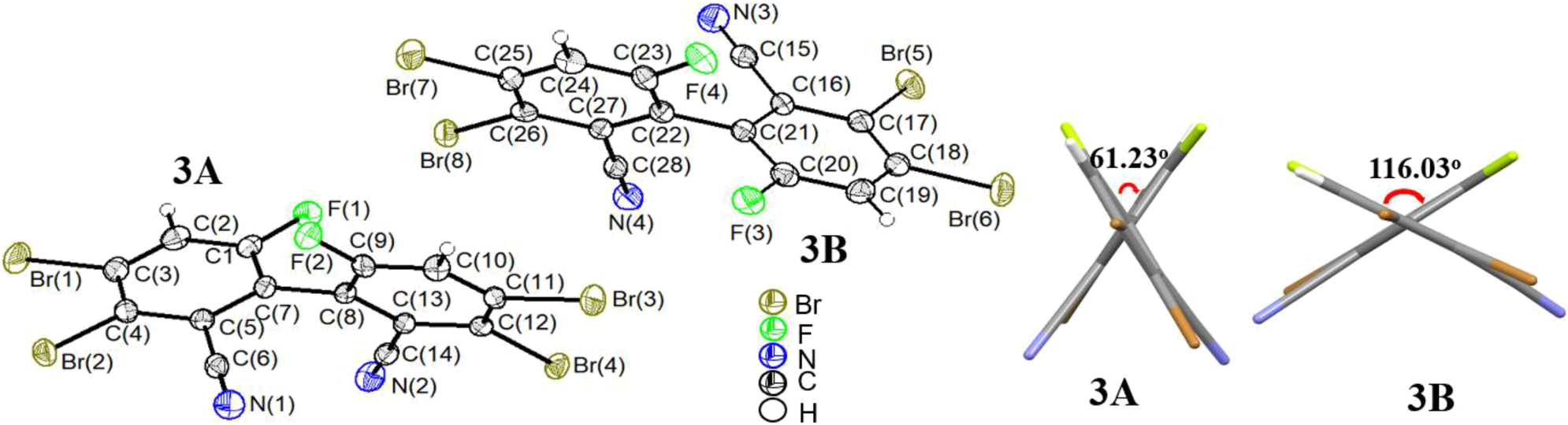
Molecular structure of compound 3 (left; two independent molecules 3A and 3B; displacement ellipsoids are drawn at the 30 % probability level, H atoms as spheres with arbitrary radii) and dihedral angles of the biphenyls (right).
In the crystals of compound 3, there are intermolecular C–H⋯N (H(2)⋯N(2) 2.535 Å) hydrogen bonding and a number of C–Br⋯π halogen bonding 28 , 29 (Br⋯centroids distances of 3.501–3.843 Å) interactions (Figure 9).
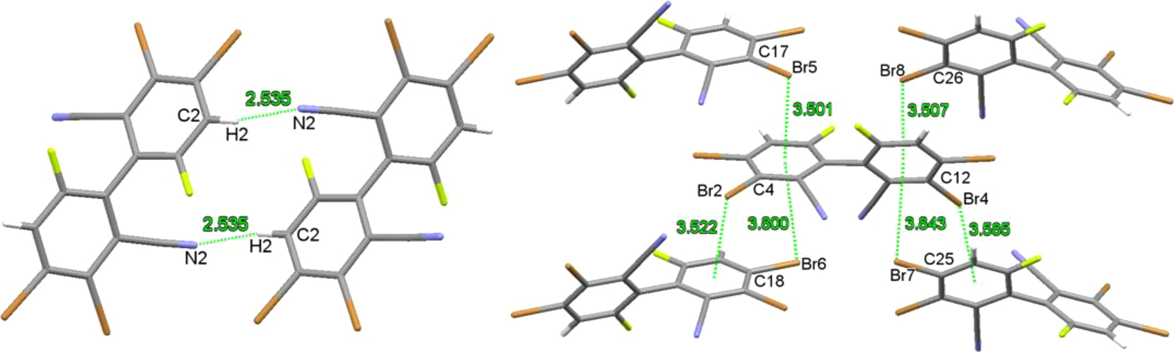
Weak intermolecular interactions in crystals of compound 3.
Single crystals of compound 6 were grown from a chloroform solution. The compound crystallizes in the monoclinic space group I2 with Z = 4. There are two crystallographically independent molecules 6A and 6B, each of which has crystallographic 2 (C 2) symmetry, the two-fold axes bisecting the central biphenyl C–C bonds (Figure 10). The C–C bond lengths between the benzene rings of the two molecules are 1.508(9) Å (C19–C19) and 1.479(11) Å (C38–C38), respectively, similar to that of 1.502(5) Å in compound D, 5 indicating that the different bromine positions have little effect on the length of this C–C bonds. The C–Br bond lengths in compound 6 are 1.906(5) Å (C16–Br1) and 1.916(7) Å (C35–Br2), respectively, similar to those in the above-mentioned structures. The dihedral angles of its biphenyl framework are 64.08° and 70.63° for the two independent molecules. The corresponding dihedral angles between the planes of the carbazolyl and the biphenyl are 71.3° and 61.38°, respectively (Figure 10). In addition, weak intermolecular C–H⋯π (C(14)–H(14)⋯Cg1/C(15)–H(15)⋯Cg2) and C–H⋯N (C(4)–H(4)⋯N(2)/C(9)–H(9)⋯N(2)) hydrogen bonding interactions and the intramolecular π⋯π stacking of the carbazolyl rings are present in crystals of compound 6 (Figure 11).
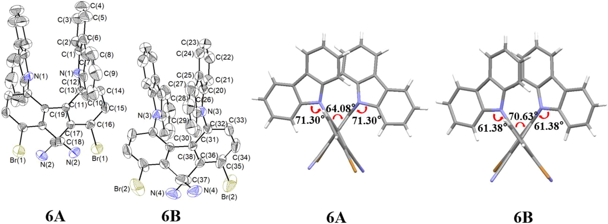
Molecular structure of compound 6 (left; two independent molecules 6A and 6B; displacement ellipsoids are drawn at the 30 % probability level, H atoms as spheres with arbitrary radii) and dihedral angles of the biphenyl (right).

Weak intra- and intermolecular interactions in crystals of compound 6.
3.4 Electronic structures of compounds
DFT methods 25 have been utilized to study the electronic structures of compounds A and 1–3, and their optimized structures and frontier molecular orbital composition/energy levels are shown in Figures 12 and 13, respectively. The HOMO of compound 1 is mainly concentrated on the benzene rings, the bromine and fluorine atoms, and the cyano group is much less involved, while the LUMO mainly resides on the cyano group and biphenyl skeleton. Similar to that in 1, the HOMO of compound 3 is mainly concentrated on the biphenyl skeleton, bromine and fluorine atoms, and the LUMO is mainly distributed on the biphenyl skeleton and cyan group, with trace on the bromine atoms; and the HOMO of compound 2 is mainly distributed on the nitro group and one benzene ring and fluorine atom, with a small amount of distribution on the other benzene ring, and LUMO is mainly on the nitro group and one benzene ring and cyan group. Compared with compound A, the HOMO energy level of compound 1 is essentially unchanged, but that of compound 3 is slightly decreased and that of compound 2 is significantly increased. The LUMO energy levels of compounds 1–3 decreased to different extent when compared to that of compound A. The HOMO-LUMO energy gaps of compounds 1–3 are all significantly lower than that of compound A. The above results show that the different substitutions lead to the differences in the electronic structures.

Optimized structures of compounds 1–3 at the B3LYP/6-31G (d,p) level of theory.

Frontier molecular orbitals and energy levels of compounds A and 1–3 (B3LYP/6-31G (d,p) level).
As to compound 6 (Figure 14), the HOMO mainly resides on the two carbazolyl rings, and the LUMO mainly on the two cyano groups and the biphenyl framework, as expected. The corresponding singlet-triplet energy gap (ΔE ST) is calculated to be 0.09 eV, which is well within the range (< 0.3 eV) expected for a system with TADF property. 3
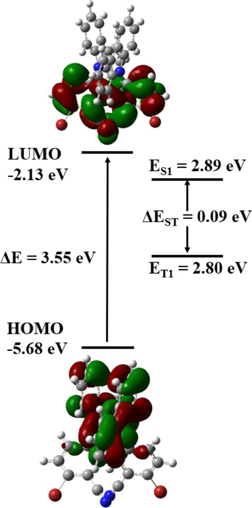
Frontier molecular orbitals and energy levels, and the singlet-triplet energy gap of compound 6 (B3LYP/6-31G (d,p) level).
3.5 Optical properties
The UV absorption spectra of compounds 1–3 were measured in THF solutions at room temperature (Figure 15). All three compounds show two absorption peaks, with a stronger one at 225–228 nm (compound 1: 225 nm, compound 2: 227 nm; compound 3: 228 nm) and a weaker one at 302–314 nm (compound 1: 303 nm, 2: 302 nm, 3: 314 nm), respectively. In this case, the short wavelength absorption peak is attributed to the intramolecular π→π* electron transition and the longer wavelength absorption peak is assigned to the intramolecular charge transfer. 6 , 8 , 9
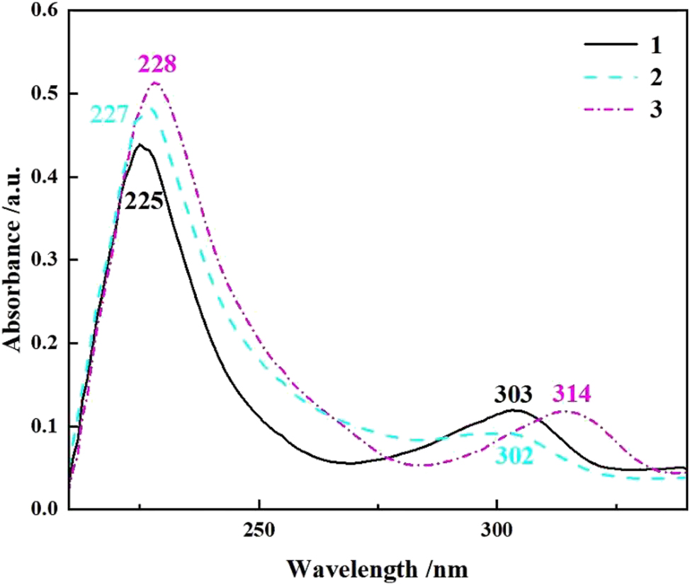
UV absorption spectra of compounds 1–3 (THF, c = 10−5 mol L−1).
The UV absorption spectrum of compound 6 in toluene was measured at room temperature (Figure 16). It shows a strong absorption band at 287 nm attributable to the intramolecular π→π* transition of the aromatic rings, and a weak absorption band at 330 nm due to the intramolecular charge transfer transition. The absorption bands of compound 6 are red-shifted compared to those of 1–3, but similar to those of the analogous compounds B (in toluene) 9 and D (in 2-MeTHF). 5
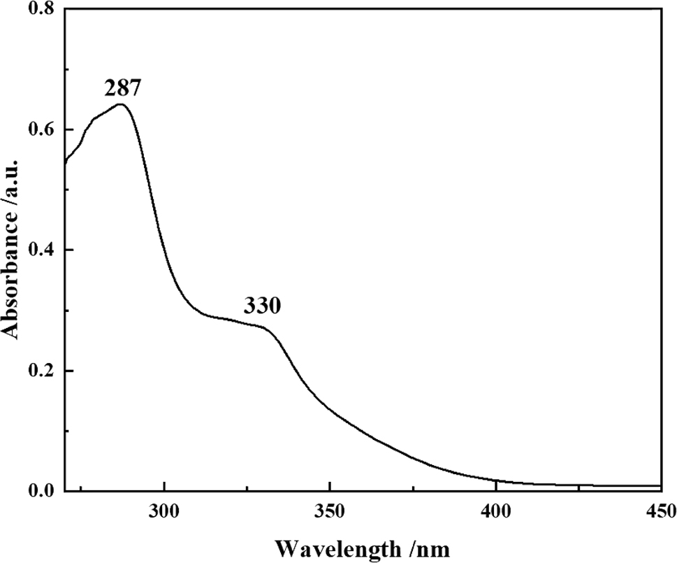
UV absorption spectrum of compound 6 (toluene, c = 10−5 mol L−1).
The emission spectra of compound 6 were measured in THF-H2O system at room temperature with different water fractions (Figure 17). The compound is hardly emissive in dilute THF solution. As the water fraction increases to 90 %, the emission is significantly enhanced. At a water fraction of 98 %, the emission is the strongest. This may be due to the formation of molecular aggregates, which increases the rigidity of the molecules and hinders the internal rotations, resulting in enhanced emission and exhibiting typical Aggregation-Induced Emission (AIE) properties. 30 For a sample with fw = 98 % after 30 min, the emission intensity further increases indicating that the emission of the aggregates is time-dependent. Under these conditions, the emissions are first red-shifted (518–543 nm) and then blue-shifted (543–504 nm). These changes are mainly caused by the differences in the aggregates formed. For comparison, compound B also displays AIE phenomenon, 9 whereas compound D is emissive in both solution and film states, indicating that different bromination position has significant effect on the emission property in this system.

Fluorescence spectra of compound 6 in THF-H2O (c = 1 × 10⁻⁵ mol L−1, λ ex = 330 nm) with different water fractions (fw) and the one with fw = 98 % after 30 min (left), and the corresponding changes in intensity and wavelength (insets: photos of the systems under UV light at 365 nm).
The solid-state fluorescence spectrum of compound 6 was measured at room temperature (Figure 18), with an emission maximum at 503 nm, very similar to those of compound B (in methanol) 9 and D (in 2-MeTHF), 5 indicating that the bromination (position) and the state of the compound have little effect on the emission wavelength. The powder of compound 6 exhibits strong emission with an absolute quantum yield of 72 %, at the higher end in the reported PLQYs of AIDF materials. 31 The photoluminescence decay curve of the doped film (in 9,9′-(1,3-phenylene)bis-9H-carbazole, mCP) displays a transient fluorescence lifetime of 0.64 ns and a delayed fluorescence lifetime of 5.1 μs (Figure 19). The former lifetime can be attributed to the fluorescence of the S1 to S0 transition; Due to the small ΔEST of compound 6, the latter lifetime comes from the efficient reverse intersystem crossing (RISC) process of T1 upconversion to S1 followed by radiative decay. These results indicate that compound 6 is TADF-active. Combining the AIE and TADF properties, compound 6 exhibits AIDF characteristics.
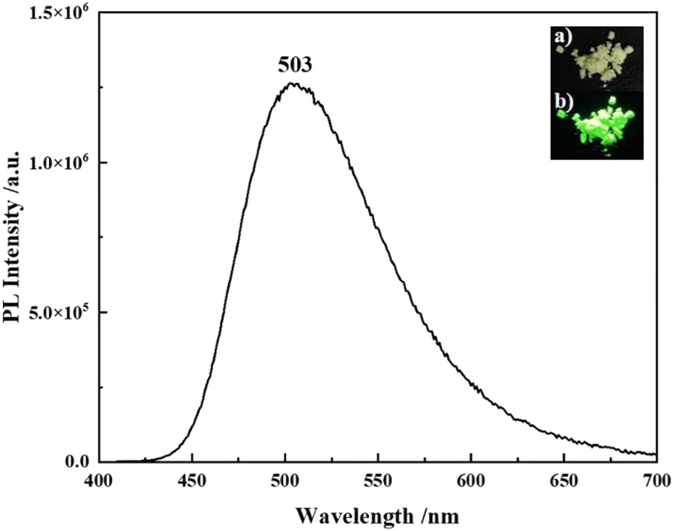
Fluorescence spectrum of compound 6 in powder (λ ex = 400 nm) (insets: photos of the powder under ambient (top) and UV light at 365 nm (bottom)).
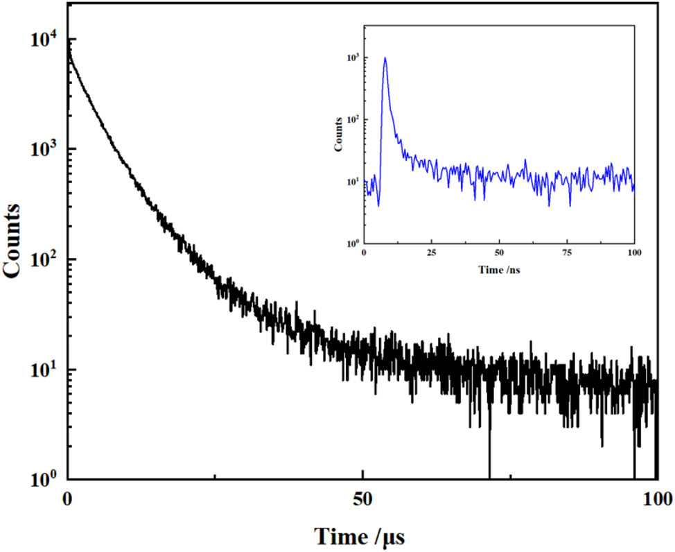
Delayed fluorescence decay curve of compound 6 in powder (5 wt% in mCP) (inset: the corresponding transient decay curve).
4 Summary
The one-step reaction of the electron-deficient biphenyl compound 6,6′-difluoro-1,1′-biphenyl-2,2′-dicarbonitrile (A) with elemental bromine in mixed acids led mainly to the corresponding brominated biphenyl products 1 and 3 at the 3,3′-positions. Compound 1 reacts with carbazole to form compound 6 which is both TADF- and AIE-active (i.e. AIDF-active). The synthesis of emissive compound 6 provides new research opportunities for the subsequent synthesis of related organic optoelectronic materials (e.g. via metal-catalyzed coupling reactions or further synthesis of the related (axially) chiral compounds) and devices.
5 Supporting information
The 1H NMR, 13C NMR, IR and MS spectra of compounds 1–3 and 6, GC-MS results of compounds 4 and 5, low resolution mass spectrometry of mixtures 6–8, molecular stacking diagrams and crystal data of compounds 1–3 and 6, are given as supplementary material available online (https://doi.org/10.1515/znb-2025-0004).
CCDC 2369405, 2369404, 2370364 and 2413554 contain the supplementary crystallographic data for this paper. These data can be obtained free of charge from the Cambridge Crystallographic Data Centre via www.ccdc.cam.ac.uk/data_request/cif.
Acknowledgments
We thank the Natural Science Foundation of Shandong Province (grants ZR2022MB107 and ZR2020MB001 ) for support of this work.
-
Research ethics: Not applicable.
-
Informed consent: Not applicable.
-
Author contributions: All authors have accepted responsibility for the entire content of this submitted manuscript and approved submission.
-
Use of Large Language Models, AI and Machine Learning Tools: None declared.
-
Conflict of interest: The authors declare no conflict of interest regarding this article.
-
Research funding: Natural Science Foundation of Shandong Province (grants ZR2022MB107 and ZR2020MB001).
-
Data availability: The raw data can be obtained on request from the corresponding author.
References
1. Uoyama, H.; Goushi, K.; Shizu, K.; Nomura, H.; Adachi, C. Nature 2012, 492, 234–238; https://doi.org/10.1038/nature11687.Search in Google Scholar PubMed
2. Liang, X.; Tu, Z. L.; Zheng, Y. X. Chem. Eur. J. 2019, 25, 5623–5642; https://doi.org/10.1002/chem.201805952.Search in Google Scholar PubMed
3. Li, M.; Chen, C.-F. Org. Chem. Front. 2022, 9, 6441–6452; https://doi.org/10.1039/d2qo01383e.Search in Google Scholar
4. Wang, Y.-F.; Li, M.; Zhao, W.-L.; Shen, Y.-F.; Lu, H.-Y.; Chen, C.-F. Chem. Commun. 2020, 56, 9380–9383; https://doi.org/10.1039/d0cc03822a.Search in Google Scholar PubMed
5. Zhang, D. W.; Li, M.; Chen, C. F. Angew. Chem. Int. Ed. 2022, 61, e202213130 (5 pages) https://doi.org/10.1002/anie.202213130.Search in Google Scholar PubMed
6. Tan, K.-K.; Zhang, D.-W.; Zhao, W.-L.; Li, M.; Chen, C.-F. Chem. Eng. J. 2023, 462, 142123 (8 pages) https://doi.org/10.1016/j.cej.2023.142123.Search in Google Scholar
7. Wan, S.-P.; Zhao, W.-L.; Tan, K.-K.; Lu, H.-Y.; Li, M.; Chen, C.-F. Chem. Eng. J. 2023, 468, 143508 (8 pages) https://doi.org/10.1016/j.cej.2023.143508.Search in Google Scholar
8. Guo, C.-H.; Zhao, W.-L.; Tan, K.-K.; Guo, W.-C.; Feng, L.; Chen, C.-F.; Li, M. Sci. China Chem. 2024, 67, 2039–2045; https://doi.org/10.1007/s11426-024-2017-8.Search in Google Scholar
9. Li, M.; Wang, Y. F.; Zhang, D.; Duan, L.; Chen, C. F. Angew. Chem. Int. Ed. 2020, 59, 3500–3504; https://doi.org/10.1002/anie.201914249.Search in Google Scholar PubMed
10. Tu, Z. L.; Yan, Z. P.; Liang, X.; Chen, L.; Wu, Z. G.; Wang, Y.; Zheng, Y. X.; Zuo, J. L.; Pan, Y. Adv. Sci. 2020, 7, 2000804 (6 pages); https://doi.org/10.1002/advs.202000804.Search in Google Scholar PubMed PubMed Central
11. Tu, Z. L.; Lu, J. J.; Luo, X. F.; Hu, J. J.; Li, S.; Wang, Y.; Zheng, Y. X.; Zuo, J. L.; Pan, Y. Adv. Opt. Mater. 2021, 9, 2100596 (7 pages) https://doi.org/10.1002/adom.202100596.Search in Google Scholar
12. Andrievsky, A. M.; Gorelik, M. V. Russ. Chem. Rev. 2011, 80, 421–428; https://doi.org/10.1070/rc2011v080n05abeh004178.Search in Google Scholar
13. Sun, X.; Shan, G.; Sun, Y.; Rao, Y. Angew. Chem. Int. Ed. 2013, 52, 4440–4444; https://doi.org/10.1002/anie.201300176.Search in Google Scholar PubMed
14. Niu, S.; Mao, L.-L.; Xiao, H.; Zhao, Y.; Tung, C.-H.; Wu, L.-Z.; Cong, H. Chin. Chem. Lett. 2022, 33, 1970–1974; https://doi.org/10.1016/j.cclet.2021.09.090.Search in Google Scholar
15. Bovicelli, P.; Antonioletti, R.; Onori, A.; Delogu, G.; Fabbri, D.; Dettori, M. A. Tetrahedron 2006, 62, 635–639; https://doi.org/10.1016/j.tet.2005.10.009.Search in Google Scholar
16. Gustafson, J. L.; Lim, D.; Miller, S. J. Science 2010, 328, 1251–1255; https://doi.org/10.1126/science.1188403.Search in Google Scholar PubMed PubMed Central
17. Mori, K.; Ichikawa, Y.; Kobayashi, M.; Shibata, Y.; Yamanaka, M.; Akiyama, T. J. Am. Chem. Soc. 2013, 135, 3964–3970; https://doi.org/10.1021/ja311902f.Search in Google Scholar PubMed
18. Andrievsky, A. M.; Gorelik, M. V.; Open, J. Synth. Theory Appl. 2013, 2, 46–50.10.4236/ojsta.2013.21005Search in Google Scholar
19. Voskressensky, L.; Golantsov, N.; Maharramov, A. Synthesis 2016, 48, 615–643; https://doi.org/10.1055/s-0035-1561503.Search in Google Scholar
20. Cao, J.; Li, M.; Sui, Y.; Hua, R. Chin. J. Org. Chem. 2013, 33, 2349–2356; https://doi.org/10.6023/cjoc201306029.Search in Google Scholar
21. Li, Z.; Tang, B. Z.; Wang, D. Adv. Mater. 2024, 36, 2406047 (19 pages).Search in Google Scholar
22. Li, J.; Zhuang, Z.; Lou, X.; Zhao, Z.; Tang, B. Z. Chem. Biomed. Imaging 2023, 1, 785–795; https://doi.org/10.1021/cbmi.3c00038.Search in Google Scholar PubMed PubMed Central
23. Furue, R.; Nishimoto, T.; Park, I. S.; Lee, J.; Yasuda, T. Angew. Chem. Int. Ed. 2016, 55, 7171–7175; https://doi.org/10.1002/anie.201603232.Search in Google Scholar PubMed
24. Huang, J.; Nie, H.; Zeng, J.; Zhuang, Z.; Gan, S.; Cai, Y.; Guo, J.; Su, S.-J.; Zhao, Z.; Tang, B. Z. Angew. Chem. Int. Ed. 2017, 56, 12971–12976; https://doi.org/10.1002/anie.201706752.Search in Google Scholar PubMed
25. Frisch, M. J.; Trucks, G. W.; Schlegel, H. B.; Scuseria, G. E.; Robb, M. A.; Cheeseman, J. R.; Scalmani, G.; Barone, V.; Mennucci, B.; Petersson, G. A.; Nakatsuji, H.; Caricato, M.; Li, X.; Hratchian, H. P.; Izmaylov, A. F.; Bloino, J.; Zheng, G.; Sonnenberg, J. L.; Hada, M.; Ehara, M.; Toyota, K.; Fukuda, R.; Hasegawa, J.; Ishida, M.; Nakajima, T.; Honda, Y.; Kitao, O.; Nakai, H.; Vreven, T.; MontgomeryJrJ. A.; Peralta, J. E.; Ogliaro, F.; Bearpark, M.; Heyd, J. J.; Brothers, E.; Kudin, K. N.; Staroverov, V. N.; Kobayashi, R.; Normand, J.; Raghavachari, K.; Rendell, A.; Burant, J. C.; Iyengar, S. S.; Tomasi, J.; Cossi, M.; Rega, N.; Millam, J. M.; Klene, M.; Knox, J. E.; Cross, J. B.; Bakken, V.; Adamo, C.; Jaramillo, J.; Gomperts, R.; Stratmann, R. E.; Yazyev, O.; Austin, A. J.; Cammi, R.; Pomelli, C.; Ochterski, J. W.; Martin, R. L.; Morokuma, K.; Zakrzewski, V. G.; Voth, G. A.; Salvador, P.; Dannenberg, J. J.; Dapprich, S.; Daniels, A. D.; Farkas, Ö.; Foresman, J. B.; Ortiz, J. V.; Cioslowski, J.; Fox, D. J. Gaussian 09, (Revision A.02); Gaussian, Inc.: Wallingford CT (USA), 2009.Search in Google Scholar
26. Balaban, M. C.; Chappaz-Gillot, C.; Canard, G.; Fuhr, O.; Roussel, C.; Balaban, T. S. Tetrahedron 2009, 65, 3733–3739; https://doi.org/10.1016/j.tet.2009.02.039.Search in Google Scholar
27. Li, P.; Vik, E. C.; Shimizu, K. D. Acc. Chem. Res. 2020, 53, 2705–2714; https://doi.org/10.1021/acs.accounts.0c00519.Search in Google Scholar PubMed
28. Matter, H.; Nazaré, M.; Güssregen, S.; Will, D. W.; Schreuder, H.; Bauer, A.; Urmann, M.; Ritter, K.; Wagner, M.; Wehner, V. Angew. Chem., Int. Ed. 2009, 48, 2911–2916; https://doi.org/10.1002/anie.200806219.Search in Google Scholar PubMed
29. Ang, S. J.; Mak, A. M.; Sullivan, M. B.; Wong, M. W. Phys. Chem. Chem. Phys. 2018, 20, 8685–8694; https://doi.org/10.1039/c7cp08343b.Search in Google Scholar PubMed
30. Luo, J.; Xie, Z.; Lam, J. W. Y.; Cheng, L.; Chen, H.; Qiu, C.; Kwok, H. S.; Zhan, X.; Liu, Y.; Zhu, D.; Tang, B. Z. Chem. Commun. 2001, 1740–1741; https://doi.org/10.1039/b105159h.Search in Google Scholar PubMed
31. Huo, Y.; Ji, S.; Chen, W.-C.; Gao, Y.; Qiu, Z.; Huang, C. Chin. J. Org. Chem. 2021, 41, 3050–3072; https://doi.org/10.6023/cjoc202101053.Search in Google Scholar
Supplementary Material
This article contains supplementary material (https://doi.org/10.1515/znb-2025-0004).
© 2025 Walter de Gruyter GmbH, Berlin/Boston
Articles in the same Issue
- Frontmatter
- In this issue
- Research Articles
- Chemical aspects of the preparation of Vulcanised Fibre using zinc chloride hydrates: from a brief history to a new consideration of the key reactions in ionic liquids
- On the preparation and spectral properties of some hydroxy-substituted triphenylmethane dyes
- High-pressure synthesis and crystal structure of Ga5Na1–x B12O26–x (OH) x (x = 0.12)
- Intermetallic phases with Ho4Ir13Ge9-type structure
- Interplay between oxidative addition and reductive elimination at a diruthenium complex bearing the bis(diphenylphosphanyl)amine ligand
- Anthracene-d- and l-phenylalanine derivatives: synthesis, dual-state emission, mechanochromic luminescence, chiroptical property and enantioselective recognition of free amino acids
- Synthesis, structures and optical properties of 3,3′-disubstituted biphenyl compounds