
Bifunctional spoof surface plasmon polariton meta-coupler using anisotropic transmissive metasurface
-
Dengpan Wang
 ,
Shiwei Tang
und
Tong Cai
,
Shiwei Tang
und
Tong Cai


Abstract
Tailoring the wavefronts of spoof surface plasmon polaritons (SSPPs) at will, especially with multifunctional integration, is of great importance in near-field photonics. However, conventional SSPP devices suffer from the issues of bulk configurations, limited functionalities, and single operating modes, which are unfavorable for electromagnetic (EM) integration. Here, a novel scheme is proposed to design bifunctional SSPP meta-devices based on the polarization dependent property via satisfying the comprehensive phase distributions and multi-mode momentum matching in a transmission geometry. As proof of the concept, we experimentally demonstrate a bifunctional SSPP meta-device in the microwave regime that can convert incident x- and y-polarized waves to transverse magnetic (TM)-mode SSPP Bessel beams and transverse electric (TE)-mode SSPP focusing beams, respectively. Our findings open a door to achieve near-field manipulation of SSPPs with multi-function and multi-mode integration, which can stimulate the applications of SSPP functional devices, such as near-field sensing, imaging, and on-chip photonics.
1 Introduction
Spoof surface plasmon polaritons (SSPPs), the low-frequency (e.g., THz and GHz) counterparts of natural surface plasmon polaritons (SPPs), are the electromagnetic (EM) eigenmodes that bounded at dielectric/metal interfaces, which exhibit the extraordinary properties of sub-wavelength resolution and local field enhancement [1], [2], [3], [4], [5], [6], [7], [8]. SSPPs have displayed many fascinating applications, such as in antennas [9], [10], [11], [12], integrated wireless communication systems [13], waveguides [14], imaging [15, 16], sub-wavelength circuits [17], and near-field photonics areas [18]. Generally, to achieve those promising applications, it is necessary to excite the SSPPs with tailored wavefronts efficiently and flexibly. Traditionally, prisms or gratings are employed to excite the SSPPs, while transportation phase accumulations or Bragg scatterings with grooves and slits patterned on SSPP eigenmode plates are utilized to tailor the wavefronts of SSPPs [19], [20], [21], [22], [23]. However, these methods have the disadvantages of bulk configurations, limited functionalities, and single operating modes, which are unfavorable for highly integrated modern devices [24].
Recently, multifunctional metasurfaces have attracted a great deal of attention due to their powerful wavefront manipulation capability, yielding various fascinating propagation wave (PW) manipulation effects, such as full-space manipulation [24], [25], [26], spin-decoupling or selection [27], [28], [29], [30], information- or time-space coding [31], [32], [33], [34], and many others [35], [36], [37], [38], [39], [40], [41], [42], [43], [44], [45], [46], [47]. Meanwhile, high-efficiency SSPP meta-couplers based on metasurfaces have been proposed, including unidirectional SSPP meta-couplers [48], [49], [50], [51], [52] and polarization-controlled tunable and functional meta-couplers [53], [54], [55], [56], [57], but the impossibility of SSPP wavefront manipulation limits their applications. The trend in modern science and technology has been to implement SSPP multifunctional integration with arbitrary wavefronts and modes. In 2018, plasmon metal plates, together with an additional reflective all-dielectric metasurface, were employed to manipulate the wavefront of the excited SSPP [58]. Very recently, a kind of ultra-thin reflective metasurface with Pancharatnam–Berry (PB) phase efficiently excited transverse magnetic (TM)-mode SSPPs with tailored wavefronts [59, 60]. Despite these achievements, most of the reported meta-devices are limited by their single SSPP mode (only the TM mode), since it is difficult to support a transverse electric (TE) SSPP mode for a negative permeability medium with the momentum-matching requirement of the SSPP eigenmode plate. Meanwhile, it is promising to excite and match the momentum of a multi-mode and multi-function SSPP in a transmission geometry, because the obtained field avoids interference with the incident waves.
In this paper, we propose a novel scheme to efficiently excite both TM- and TE-mode SSPPs with arbitrary wavefronts integrated on a single device in the transmission geometry. For verification, a bifunctional SSPP meta-coupler is designed, fabricated, and experimentally demonstrated in the microwave regime. This coupler efficiently converts incident x- and y-polarized waves to TM-mode SSPP Bessel beams and TE-mode SSPP focusing beams with opposite directions of propagation, as schematically illustrated in Figure 1. The anisotropic transmissive metasurfaces are employed to satisfy the desired multifunctional SSPP phase distributions with high transmission amplitudes and the dispersion-controlled SSPP eigenmode plate is introduced to match the momentum of the multi-mode SSPP. Our findings substantially enrich the application scenarios of SSPP near-field manipulation with multi-function and multi-mode integration.
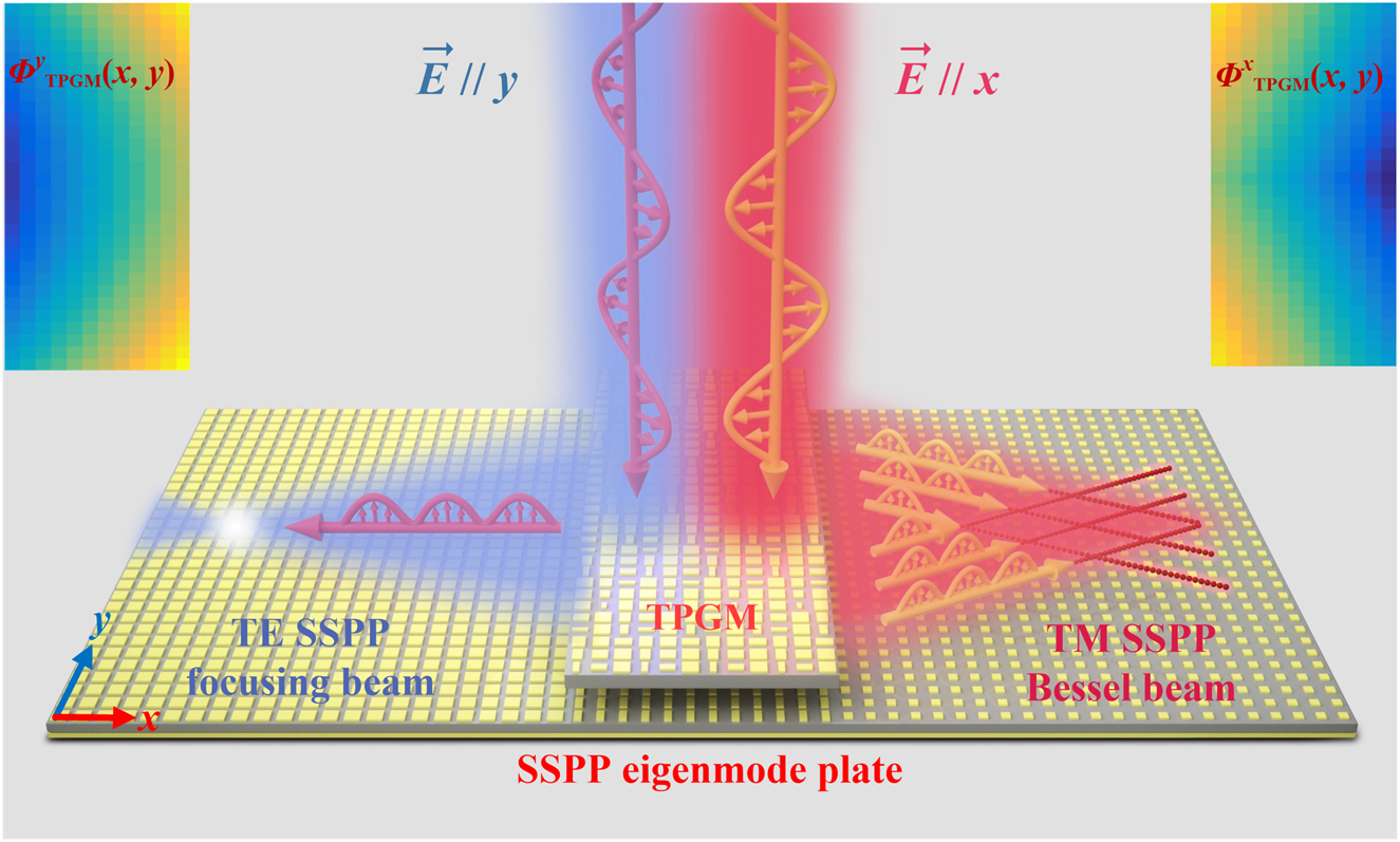
Schematic of the designed bifunctional SSPP meta-coupler. When the y-polarized plane wave is incident on the top layer (TPGM), the TE-mode SSPP focusing beam on the bottom layer is generated, which travels to the left. For the x-polarized incident plane wave, the TM-mode SSPP Bessel beam is excited and flows to the right side. The two inset color maps are the theoretical phase distributions of y polarization and x polarization for the TPGM.
2 Principle and design
2.1 Working principle of the bifunctional SSPP meta-coupler
To excite SSPPs with high efficiency, scientists usually designed metasurfaces with a linear phase profile
where
To implement TM- and TE-mode SSPPs with two different functions on a single meta-device as shown schematically in Figure 1, the whole device is composed of two layers of plates. The top layer is composed of an anisotropic transmissive phase gradient metasurface (TPGM) with different phase profiles for x- and y-polarized waves. The comprehensive phase distribution of this anisotropic TPGM can be expressed as:
where
As we all know, gradient phase metasurfaces are a good choice for SSPP couplers, but they cannot guide to form the SSPPs because the energy is bounded on the metasurfaces. As a result, we need to design an SSPP eigenmode plate to form and support the propagation of the SSPPs. For the reflective SSPP coupler, the SSPP eigenmode plates are always placed next to the SSPP coupler made from a gradient phase metasurface [2]. However, for such a setup, the TE mode SSPP is difficult to couple out to the SSPP eigenmode plate, even if the SSPP eigenmode plate supports that mode. To solve this problem, we designed a transmissive SSPP coupler in which the SSPP eigenmode plate is placed on the bottom layer, which can couple out both the TM and TE modes of SSPPs and also support their propagation.
2.2 Transmissive metasurface and SSPP eigenmode plate designs
Figure 2(a) shows the proposed composite metasurface composing of four metallic layers separated by three dielectric substrates. The metasurface exhibits global mirror symmetry, and its EM characteristics can thus be described by two diagonal Jones matrices
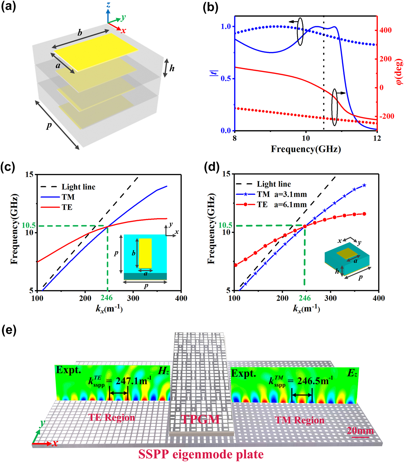
The design and performance of transmissive metasurface and SSPP eigenmode plate. (a) Schematic of the composite metasurface. The substrate is composed of F4B with relative permittivity 3.5, loss tangent 0.002, period p = 8.5 mm, and thickness h = 2 mm. The metal is copper with conductivity σ = 5.8 × 10⁷ S m−1 and thickness t = 0.036 mm. The parameters a and b are tuned based on the phase distributions. (b) The transmission amplitude and phase spectra of the metasurface (a = 4.1 mm, b = 6.4 mm) under excitation of x-polarized (dotted line) and y-polarized (solid line) waves, as obtained by FDTD simulations. (c) and (d) The FDTD simulation dispersion relation of (c) one anisotropic eigen-unit and (d) two isotropic eigen-units with the structures depicted in the inset. The anisotropic eigen-unit consists of a metallic patch on the top with parameters a = 2.5 mm and b = 6.5 mm, while the two isotropic eigen-units consist of two different square metallic patches on the top with parameters a = 3.1 mm (TM-mode isotropic eigen-unit) and a = 6.1 mm (TE-mode isotropic eigen-unit), respectively. Here, all the eigen-units are composed of metallic patches with different structural parameters and a metallic ground plane separated by a 3 mm thick dielectric substrate (ε r = 2.65 + 0.002i, with periodicity p = 8.5 mm). (e) Experimentally measured Re(H z ) and Re(E z ) field distributions on part of the fabricated SSPP eigenmode plate on the x–z plane when the meta-device is, respectively, illuminated by y-polarized and x-polarized incident waves at 10.5 GHz.
Traditionally, to support both TM- and TE-mode SSPPs coupled out from the phase gradient metasurface, an anisotropic SSPP eigenmode plate is necessary to match the momentum of the SSPP. With the wave-vector
Such an anisotropic SSPP eigenmode plate is sufficient for the conventional planar wavefront SSPP. However, because of the momentum mismatch, the anisotropic SSPP eigenmode plate does not support the oblique propagation of the SSPP very well when we try to manipulate the wavefront of the SSPP (see Section C, Supplementary Material). To resolve this problem, we design two kinds of SSPP eigenmode plates made of isotropic eigen-units to match the TM- and TE-mode SSPPs, respectively. The dispersion relations of the isotropic eigen-units are plotted in Figure 2(d), and the simulations show that all the eigen-units can support the theoretically excited SSPP at 10.5 GHz. As the fabricated sample in Figure 2(e) illustrates, two isotropic SSPP eigenmode plates are placed on each side of the anisotropic SSPP eigenmode plate to receive the SSPPs with special wavefronts.
Moreover, Figure 2(e) illustrates the experimentally measured
3 Meta-device implementation
3.1 Meta-device design
With the transmissive metasurface and SSPP eigenmode plate in hand, we next design a dual-mode SSPP bifunctional meta-coupler integrating the Bessel beam and focusing beam effects. The Bessel beam is a special type of nondiffraction beam with unique self-healing properties, attracting much interest in recent years. This beam exhibits great potential applications in near-field probing, manipulation, and so on [62]. As for the focusing beam, it can converge EM waves to one point to achieve high directivity, and is widely used in antennas and other fields [26].
To achieve bifunctional integration, the anisotropic TPGM exhibits the following comprehensive phase distributions at 10.5 GHz:
where
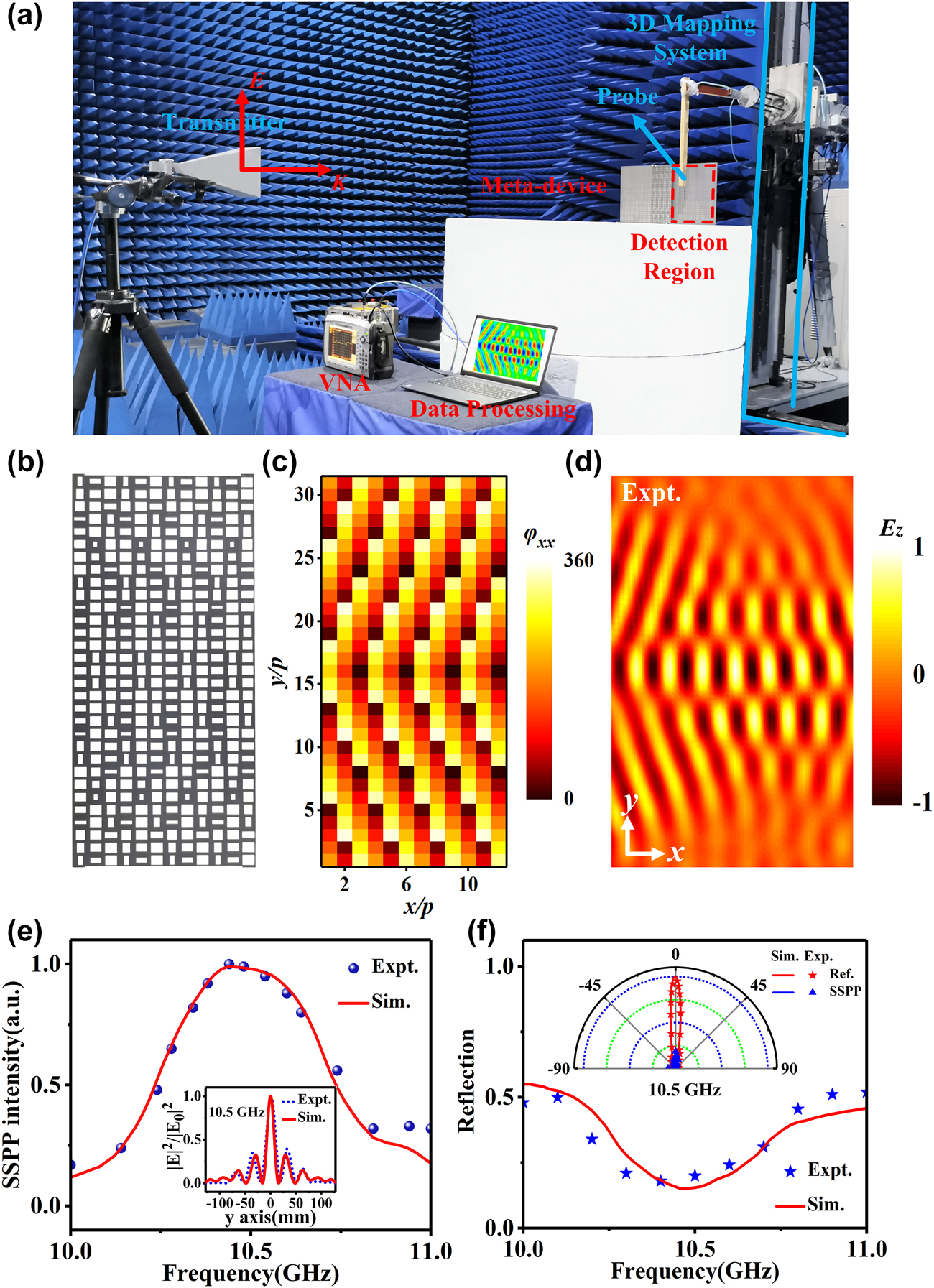
Design and experimental demonstration of the proposed meta-device with SSPP Bessel beam. (a) Near-field experimental setup and schematic diagram of the fabricated prototype meta-device with an anisotropic TPGM and a composite SSPP eigenmode plate. (b) The fabricated prototype of the TPGM. (c) Theoretically calculated and FDTD-simulated phase profiles of
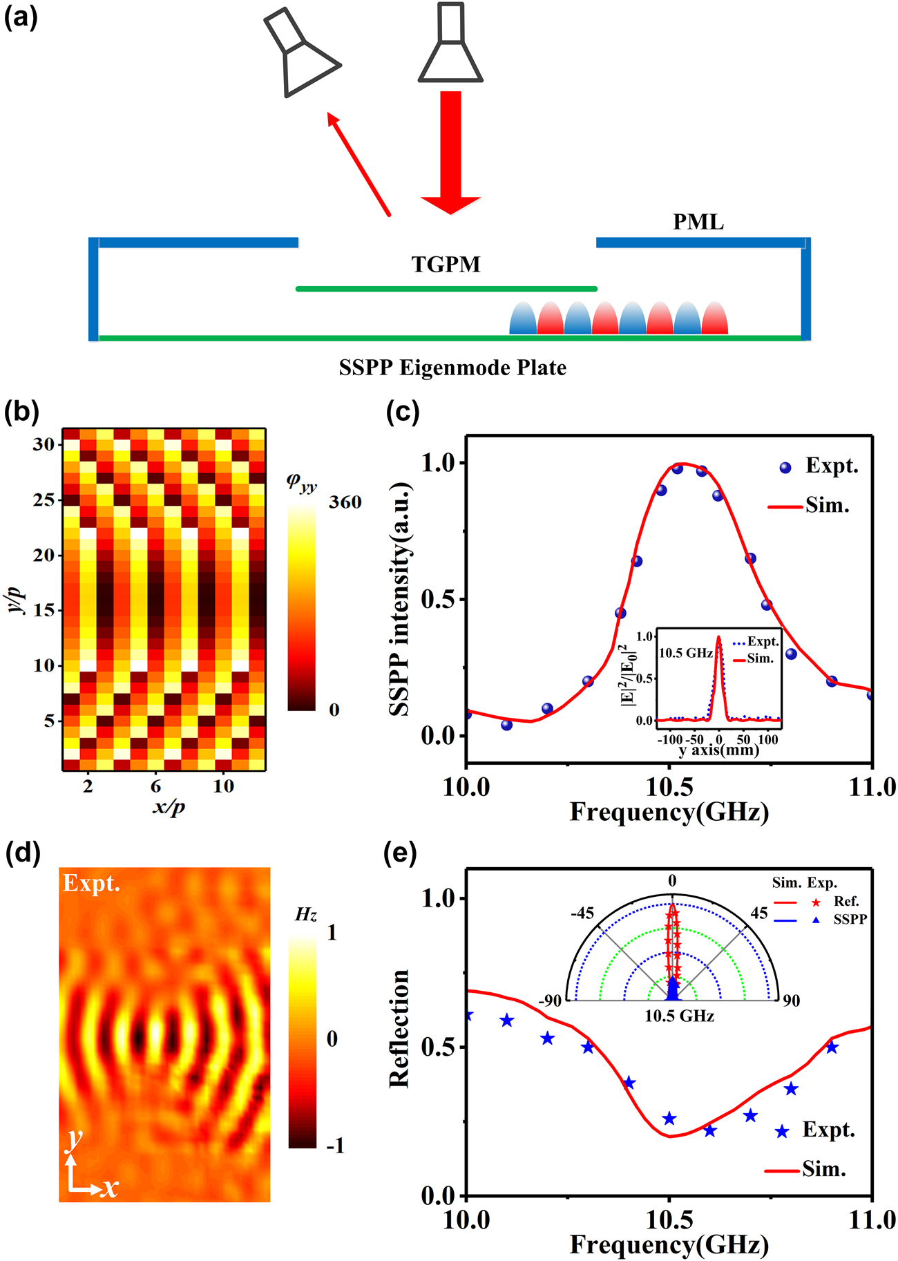
Design and experimental demonstration of the proposed meta-device with SSPP focusing beam. (a) Schematic of the far-field experimental setup. (b) Theoretical and FDTD-designed phase profiles on the TPGM. (c) Simulated and measured SSPP intensity of the SSPP focusing beam versus frequency. The inset shows the field distribution at the focal length position versus the y coordinate with F = 140 mm at 10.5 GHz. (d) Experimentally measured
3.2 Experimental verification
We fabricated a prototype meta-device containing an anisotropic TPGM and a composite SSPP eigenmode plate, and experimentally investigated its near- and far-field performance in a microwave anechoic chamber, as depicted in Figure 3(a).
We first experimentally characterized the performance of the SSPP Bessel beam. The TPGM was illuminated normally by an x-polarized wave emitted from a horn antenna, and a monopole antenna was employed to detect the local
Then, we quantitatively characterized the performance of our bifunctional meta-device through far-field experiments. As schematically illustrated in Figure 4(a), the incident wave goes to three channels: conversion into SSPP, scattering to the far-field (i.e., total reflection R), and structure absorption. Here, the structure absorption is mainly determined by the loss of the dielectric layers, and an approximate estimation value can be obtained in the simulations [3]. Therefore, the SSPP conversion efficiency, an important parameter that quantitatively describes the incident energy converted into SSPP, is mainly determined by the scattered energies. To quantitatively describe the scattered energy (i.e., total reflection), we first illuminated the meta-device by an x-polarized wave emitted from a horn antenna (8–12 GHz) and then used another horn antenna to detect the radiation patterns at different angles ranging from −90° to 90°. The inset in Figure 3(f) shows the normalized (to the metal) far-field scattering distributions of the meta-device at 10.5 GHz. As a comparison, the normalized (to the maximum value) scattering of a metallic plate with the same size as the excitation region is also given in the inset. The measured results, coinciding well with the simulated ones, show that the radiation pattern of the meta-device is drastically suppressed compared with that of the metallic plate. Moreover, we integrate the scattered waves over all angles at different frequencies to obtain the total reflected power at the corresponding frequencies, while the total incident power is calculated by integrating over the scattered energy with the excitation area covered by an equal-sized metallic plate. The ratio of the two powers describes the total reflection R of the meta-device quantitatively, as shown in Figure 3(f). Both the measured and simulated total reflection (R) curves have an obvious trough with R only about 0.17 at 10.5 GHz, indicating that the total reflection of the meta-device is very weak and the incident energy is mainly converted into SSPP. Furthermore, we have investigated the total working efficiency of the TM SSPP Bessel beam with the maximum value of 0.6, which is defined as the ratio between the power carried by the SSPP functional beam and that carried by the incident power (see Section E, Supplementary Material). Meanwhile, the crosstalk efficiency of the TM SSPP Bessel beam has also been investigated with a value of 2% at 10.5 GHz, which illustrates that there is little energy will be lost in another channel (see Section B, Supplementary Material).
Next, the focusing effect of the meta-device was investigated, using an experimental setup that is quite similar to that of the Bessel beam. Illuminating the TPGM by a normally y-polarized wave, we then utilized a coil magnetic antenna to detect the local
4 Conclusions
In this paper, a novel meta-coupler is presented, which achieves multi-function and multi-mode integration in the near-field manipulation of SSPP in a transmission system. Following the new design scheme, the proposed meta-device can, respectively, convert incident x- and y-polarized waves to TM-mode SSPP Bessel beams and TE-mode SSPP focusing beams with opposite propagating directions at 10.5 GHz. Moreover, due to the flexible designs of the phase distributions of the TPGM, arbitrary functions can be integrated on a single meta-device in the transmission system, e.g., SSPP deflected beam, focusing beam, or Bessel beam. With arbitrary functions and modes as well as multifunctional integration, the proposed single meta-device has great potential in near-field photonics working at other frequency spectra.
-
Author contribution: All the authors have accepted responsibility for the entire content of this submitted manuscript and approved submission.
-
Research funding: This work was supported by National Natural Science Foundation of China under Grant Nos. 61871394, 61901512, 62101599, 11604167, Postdoctoral Innovation Talents Support Program of China under Grant No. BX20190293, the Zhejiang Province Natural Science Foundation of China (Grant No. LY19A040004), and the China Postdoctoral Science Foundation (2020M671720).
-
Conflict of interest statement: The authors declare no conflicts of interest regarding this article.
References
[1] J. B. Pendry, L. Martinmoreno, and F. J. Garciavidal, “Mimicking surface plasmons with structured surfaces,” Science, vol. 305, no. 5685, pp. 847–848, 2004. https://doi.org/10.1126/science.1098999.Suche in Google Scholar PubMed
[2] S. Sun, Q. He, S. Xiao, Q. Xu, X. Li, and L. Zhou, “Gradient index meta-surfaces as a bridge linking propagating waves and surface waves,” Nat. Mater., vol. 11, no. 5, pp. 426–431, 2012. https://doi.org/10.1038/nmat3292.Suche in Google Scholar PubMed
[3] W. Sun, Q. He, S. Sun, and L. Zhou, “High-efficiency surface plasmon meta-couplers: concept and microwave-regime realizations,” Light Sci. Appl., vol. 5, no. 1, p. e16003, 2016. https://doi.org/10.1038/lsa.2016.3.Suche in Google Scholar PubMed PubMed Central
[4] P. F. Qin, E. P. Li, Y. H. Yang, et al.., “Spoof surface plasmonic graphene for controlling the transports and emissions of electromagnetic waves,” IEEE Trans. Microw. Theor. Tech., vol. 67, no. 1, pp. 50–56, 2018.10.1109/TMTT.2018.2874253Suche in Google Scholar
[5] W. X. Tang, H. C. Zhang, H. F. Ma, W. X. Jiang, and T. J. Cui, “Concept, theory, design, and applications of spoof surface plasmon polaritons at microwave frequencies,” Adv. Opt. Mater., vol. 7, no. 1, p. 1800421, 2018. https://doi.org/10.1002/adom.201800421.Suche in Google Scholar
[6] F. Ding and S. I. Bozhevolnyi, “A review of unidirectional surface plasmon polariton metacouplers,” IEEE J. Sel. Top. Quant. Electron., vol. 25, no. 3, pp. 1–11, 2019. https://doi.org/10.1109/jstqe.2019.2894067.Suche in Google Scholar
[7] L. P. Zhang, H. C. Zhang, Z. Gao, and T. J. Cui, “Measurement method of dispersion curves for spoof surface plasmon polaritons,” IEEE Trans. Antenn. Propag., vol. 67, no. 7, pp. 4920–4923, 2019. https://doi.org/10.1109/tap.2019.2916645.Suche in Google Scholar
[8] X. Q. Zhang, Q. Xu, L. B. Xia, et al.., “Terahertz surface plasmonic waves: a review,” Adv. Photonics, vol. 2, no. 1, p. 1, 2020. https://doi.org/10.1117/1.ap.2.1.014001.Suche in Google Scholar
[9] J. Wang, L. Zhao, Z. C. Hao, and T. J. Cui, “Wide-angle frequency beam scanning antenna based on the higher-order modes of spoof surface plasmon polariton,” IEEE Trans. Antenn. Propag., vol. 68, no. 11, pp. 7652–7657, 2020. https://doi.org/10.1109/tap.2020.2993325.Suche in Google Scholar
[10] D. P. Wang, G. M. Wang, T. Cai, et al.., “Planar spoof surface plasmon polariton antenna by using transmissive phase gradient metasurface,” Ann. Phys., vol. 532, no. 6, 2020. https://doi.org/10.1002/andp.202000008.Suche in Google Scholar
[11] Q. L. Zhang, B. J. Chen, K. F. Chan, and C. H. Chan, “High-gain millimeter-wave antennas based on spoof surface plasmon polaritons,” IEEE Trans. Antenn. Propag., vol. 68, no. 6, pp. 4320–4331, 2020. https://doi.org/10.1109/tap.2020.2970122.Suche in Google Scholar
[12] J. Zhang, X. F. Hu, H. S. Chen, and F. Gao, “Designer surface plasmons enable Terahertz Cherenkov radiation,” Prog. Electromagn. Res., vol. 169, pp. 25–32, 2020. https://doi.org/10.2528/pier20102708.Suche in Google Scholar
[13] H. C. Zhang, L. P. Zhang, P. H. He, J. Xu, and T. J. Cui, “A plasmonic route for the integrated wireless communication of subdiffraction-limited signals,” Light Sci. Appl., vol. 9, no. 1, p. 113, 2020. https://doi.org/10.1038/s41377-020-00355-y.Suche in Google Scholar PubMed PubMed Central
[14] X. X. Gao, H. C. Zhang, L. W. Wu, et al.., “Programmable multifunctional device based on spoof surface plasmon polaritons,” IEEE Trans. Antenn. Propag., vol. 68, no. 5, pp. 3770–3779, 2020. https://doi.org/10.1109/tap.2020.2969745.Suche in Google Scholar
[15] D. K. Gramotnev and S. I. Bozhevolnyi, “Plasmonics beyond the diffraction limit,” Nat. Photonics, vol. 4, no. 2, pp. 83–91, 2010. https://doi.org/10.1038/nphoton.2009.282.Suche in Google Scholar
[16] M. N. Gadalla, K. Chaudhary, C. M. Zgrabik, F. Capasso, and E. L. Hu, “Imaging of surface plasmon polaritons in low-loss highly metallic titanium nitride thin films in visible and infrared regimes,” Opt. Express, vol. 28, no. 10, pp. 14536–14546, 2020. https://doi.org/10.1364/oe.391482.Suche in Google Scholar
[17] R. Zia, J. A. Schuller, A. Chandran, and M. L. Brongersma, “Plasmonics: the next chip-scale technology,” Mater. Today, vol. 9, no. 7, pp. 20–27, 2006. https://doi.org/10.1016/s1369-7021(06)71572-3.Suche in Google Scholar
[18] W. L. Barnes, A. Dereux, and T. W. Ebbesen, “Surface plasmon subwavelength optics,” Nature, vol. 424, no. 6950, pp. 824–830, 2003. https://doi.org/10.1038/nature01937.Suche in Google Scholar PubMed
[19] A. Hohenau, J. R. Krenn, A. L. Stepanov, A. Drezet, and F. R. Aussenegg, “Dielectric optical elements for surface plasmons,” Opt. Lett., vol. 30, no. 8, pp. 893–895, 2005. https://doi.org/10.1364/ol.30.000893.Suche in Google Scholar PubMed
[20] E. Devaux, J. Y. Laluet, B. Stein, et al.., “Refractive micro-optical elements for surface plasmons: from classical to gradient index optics,” Opt. Express, vol. 18, no. 20, pp. 20610–20619, 2010. https://doi.org/10.1364/oe.18.020610.Suche in Google Scholar PubMed
[21] S. Randhawa, M. U. González, J. Renger, S. Enoch, and R. Quidant, “Design and properties of dielectric surface plasmon Bragg mirrors,” Opt. Express, vol. 18, no. 14, p. 14496, 2010. https://doi.org/10.1364/oe.18.014496.Suche in Google Scholar
[22] L. Li, T. Li, S. M. Wang, and S. N. Zhu, “Collimated plasmon beam: nondiffracting versus linearly focused,” Phys. Rev. Lett., vol. 110, no. 4, p. 046807, 2013. https://doi.org/10.1103/PhysRevLett.110.046807.Suche in Google Scholar PubMed
[23] Y. G. Chen and Z. Y. Li, “Three-dimensional manipulations of surface plasmon polariton wave propagation,” Plasmonics, vol. 11, no. 5, p. 1385, 2016. https://doi.org/10.1007/s11468-016-0188-3.Suche in Google Scholar
[24] T. Cai, S. W. Tang, G. M. Wang, H. X. Xu, and S. L. Sun, “High-performance bifunctional metasurfaces in transmission and reflection geometries,” Adv. Opt. Mater., vol. 5, no. 2, p. 1600506, 2017. https://doi.org/10.1002/adom.201600506.Suche in Google Scholar
[25] T. Cai, G. M. Wang, S. W. Tang, et al.., “High-efficiency and full-space manipulation of electromagnetic wave-fronts with metasurfaces,” Phys. Rev. Appl., vol. 8, no. 3, p. 034033, 2017. https://doi.org/10.1103/physrevapplied.8.034033.Suche in Google Scholar
[26] H. L. Wang, H. F. Ma, M. Chen, S. Sun, and T. J. Cui, “A reconfigurable multifunctional metasurface for full-space control of electromagnetic waves,” Adv. Funct. Mater., vol. 31, no. 25, p. 2100275, 2021. https://doi.org/10.1002/adfm.202100275.Suche in Google Scholar
[27] H. X. Xu, L. Han, Y. Li, and Y. M. Sun, “Completely spin-decoupled dual phase hybrid metasurfaces for arbitrary wavefront control,” ACS Photonics, vol. 6, no. 1, pp. 211–220, 2018. https://doi.org/10.1021/acsphotonics.8b01439.Suche in Google Scholar
[28] W. W. Liu, Z. C. Li, Z. Li, et al.., “Energy-tailorable spin-selective multifunctional metasurfaces with full fourier components,” Adv. Mater., vol. 31, no. 32, p. 1901729, 2019. https://doi.org/10.1002/adma.201901729.Suche in Google Scholar PubMed
[29] Y. H. Xu, Q. Li, X. Q. Zhang, et al.., “Spin-decoupled multifunctional metasurface for asymmetric polarization generation,” ACS Photonics, vol. 6, no. 11, pp. 2933–2941, 2019. https://doi.org/10.1021/acsphotonics.9b01047.Suche in Google Scholar
[30] G. W. Ding, K. Chen, X. Y. Luo, J. M. Zhao, T. Jiang, and Y. J. Feng, “Dual-helicity decoupled coding metasurface for independent spin-to-orbital angular momentum conversion,” Phys. Rev. Appl., vol. 11, no. 4, p. 044043, 2019. https://doi.org/10.1103/physrevapplied.11.044043.Suche in Google Scholar
[31] L. Li, T. J. Cui, W. Ji, et al.., “Electromagnetic reprogrammable coding metasurface holograms,” Nat. Commun., vol. 8, no. 1, p. 197, 2017. https://doi.org/10.1038/s41467-017-00164-9.Suche in Google Scholar PubMed PubMed Central
[32] L. Zhang, X. Q. Chen, S. Liu, et al.., “Space-time-coding digital metasurfaces,” Nat. Commun., vol. 9, no. 1, p. 4334, 2018. https://doi.org/10.1038/s41467-018-06802-0.Suche in Google Scholar PubMed PubMed Central
[33] X. C. Wang, A. D. Rubio, H. N. Li, S. A. Tretyakov, and A. Alù, “Theory and design of multifunctional space-time metasurfaces,” Phys. Rev. Appl., vol. 13, no. 4, p. 044040, 2020. https://doi.org/10.1103/physrevapplied.13.044040.Suche in Google Scholar
[34] C. M. Wu, H. S. Yu, S. Lee, R. M. Peng, I. Takeuchi, and M. Li, “Programmable phase-change metasurfaces on waveguides for multimode photonic convolutional neural network,” Nat. Commun., vol. 12, no. 1, p. 96, 2021. https://doi.org/10.1038/s41467-020-20365-z.Suche in Google Scholar PubMed PubMed Central
[35] G. W. Ding, K. Chen, G. X. Qian, et al.., “Independent energy allocation of dual-helical multi-beams with spin-selective transmissive metasurface,” Adv. Opt. Mater., vol. 8, no. 16, p. 2000342, 2020. https://doi.org/10.1002/adom.202000342.Suche in Google Scholar
[36] K. W. Allen, D. J. P. Dykes, D. R. Reid, and R. T. Lee, “Multi-objective genetic algorithm optimization of frequency selective metasurfaces to engineer Ku-passband filter responses,” Prog. Electromagn. Res., vol. 167, pp. 19–30, 2020. https://doi.org/10.2528/pier19112609.Suche in Google Scholar
[37] Q. Dai, Z. Q. Guan, S. Chang, et al.., “A single-celled tri-functional metasurface enabled with triple manipulations of light,” Adv. Funct. Mater., vol. 30, no. 50, p. 2003990, 2020. https://doi.org/10.1002/adfm.202003990.Suche in Google Scholar
[38] H. P. Li, G. M. Wang, G. W. Hu, T. Cai, C. W. Qiu, and H. X. Xu, “3D-Printed curved metasurface with multifunctional wavefronts,” Adv. Opt. Mater., vol. 8, no. 15, p. 2000129, 2020. https://doi.org/10.1002/adom.202000129.Suche in Google Scholar
[39] X. Wan, Q. Zhang, T. Y. Chen, L. Zhang, and T. J. Cui, “Multichannel direct transmissions of near-field information,” Light Sci. Appl., vol. 8, no. 1, p. 60, 2019. https://doi.org/10.1038/s41377-019-0169-3.Suche in Google Scholar PubMed PubMed Central
[40] B. Sain, C. Meier, and T. Zentgraf, “Nonlinear optics in all-dielectric nanoantennas and metasurfaces: a review,” Adv. Photonics, vol. 1, no. 2, p. 14, 2019. https://doi.org/10.1117/1.ap.1.2.024002.Suche in Google Scholar
[41] F. Zheng, Y. J. Chen, S. W. Ji, and G. M. Duan, “Research status and prospects of orbital angular momentum technology in wireless communication,” Prog. Electromagn. Res., vol. 168, pp. 113–132, 2020. https://doi.org/10.2528/pier20091104.Suche in Google Scholar
[42] T. Cai, S. W. Tang, B. Zheng, et al.., “Ultrawideband chromatic aberration-free meta-mirrors,” Adv. Photonics, vol. 3, no. 1, 2020. https://doi.org/10.1117/1.ap.3.1.016001.Suche in Google Scholar
[43] P. Xie, G. M. Wang, H. P. Li, Y. W. Wang, and B. f. Zong, “Wideband RCS reduction of high gain Fabry-Perot antenna employing a receiver-transmitter metasurface,” Prog. Electromagn. Res., vol. 169, pp. 103–115, 2020. https://doi.org/10.2528/pier20062703.Suche in Google Scholar
[44] K. Chen, G. W. Ding, G. W. Hu, et al.., “Directional Janus metasurface,” Adv. Mater., vol. 32, no. 2, p. 1906352, 2020. https://doi.org/10.1002/adma.201906352.Suche in Google Scholar PubMed
[45] M. Z. Liu, W. Q. Zhu, P. C. Huo, et al., “Multifunctional metasurfaces enabled by simultaneous and independent control of phase and amplitude for orthogonal polarization states,” Light Sci. Appl., vol. 10, no. 107, pp. 1–11, 2021. https://doi.org/10.1038/s41377-021-00552-3.Suche in Google Scholar PubMed PubMed Central
[46] S. S. An, B. W. Zheng, H. Tang, et al.., “Multifunctional metasurface design with a generative adversarial network,” Adv. Opt. Mater., vol. 9, no. 5, p. 2001433, 2021. https://doi.org/10.1002/adom.202001433.Suche in Google Scholar
[47] Z. P. Li, G. T. Cao, C. H. Li, et al.., “Non-Hermitian electromagnetic metasurfaces at exceptional points,” Prog. Electromagn. Res., vol. 171, pp. 1–20, 2021. https://doi.org/10.2528/pier21051703.Suche in Google Scholar
[48] A. Pors, M. G. Nielsen, T. Bernardin, J. C. Weeber, and S. I. Bozhevolnyi, “Efficient unidirectional polarization-controlled excitation of surface plasmon polaritons,” Light Sci. Appl., vol. 3, no. 8, p. e197, 2014. https://doi.org/10.1038/lsa.2014.78.Suche in Google Scholar
[49] X. J. Li, G. Cheng, D. X. Yan, et al.., “One-dimensional terahertz dielectric gradient metasurface for broadband spoof surface plasmon polaritons couplers,” Opt. Lett., vol. 46, no. 2, pp. 290–293, 2021. https://doi.org/10.1364/ol.412229.Suche in Google Scholar PubMed
[50] J. W. Duan, H. J. Guo, S. H. Dong, et al.., “High-efficiency chirality-modulated spoof surface plasmon meta-coupler,” Sci. Rep., vol. 7, p. 1354, 2017. https://doi.org/10.1038/s41598-017-01664-w.Suche in Google Scholar PubMed PubMed Central
[51] X. Y. Liu, Y. J. Feng, B. Zhu, J. M. Zhao, and T. Jiang, “High-order modes of spoof surface plasmonic wave transmission on thin metal film structure,” Opt. Express, vol. 21, no. 25, pp. 31155–31165, 2013. https://doi.org/10.1364/oe.21.031155.Suche in Google Scholar
[52] Y. X. Jia, J. F. Wang, J. Yang, et al.., “Planar multi-angle retro-reflectors based on the wave-vector-reversion of spoof surface plasmon polaritons,” Opt. Express, vol. 28, no. 25, pp. 37236–37248, 2020. https://doi.org/10.1364/oe.411043.Suche in Google Scholar
[53] L. Huang, X. Chen, B. Bai, et al.., “Helicity dependent directional surface plasmon polariton excitation using a metasurface with interfacial phase discontinuity,” Light Sci. Appl., vol. 2, no. 3, p. e70, 2013. https://doi.org/10.1038/lsa.2013.26.Suche in Google Scholar
[54] S. Xiao, F. Zhong, H. Liu, S. Zhu, and J. Li, “Flexible coherent control of plasmonic spin-Hall effect,” Nat. Commun., vol. 6, p. 8360, 2015. https://doi.org/10.1038/ncomms9360.Suche in Google Scholar PubMed PubMed Central
[55] S. S. Kou, G. Yuan, Q. Wang, et al.., “On-chip photonic Fourier transform with surface plasmon polaritons,” Light Sci. Appl., vol. 5, p. e16034, 2016. https://doi.org/10.1038/lsa.2016.34.Suche in Google Scholar PubMed PubMed Central
[56] H. Mühlenbernd, P. Georgi, N. Pholchai, et al.., “Amplitude- and phase-controlled surface plasmon polariton excitation with metasurfaces,” ACS Photonics, vol. 3, no. 1, pp. 124–129, 2016.10.1021/acsphotonics.5b00536Suche in Google Scholar
[57] L. Z. Yin, T. J. Huang, F. Y. Han, J. Y. Liu, D. Wang, and P. K. Liu, “High-efficiency terahertz spin-decoupled meta-coupler for spoof surface plasmon excitation and beam steering,” Opt. Express, vol. 27, no. 13, pp. 18928–18939, 2019. https://doi.org/10.1364/oe.27.018928.Suche in Google Scholar PubMed
[58] S. H. Dong, Y. Zhu, H. J. Guo, et al.., “Highly efficient wave-front reshaping of surface waves with dielectric metawalls,” Phys. Rev. Appl., vol. 9, no. 1, p. 014032, 2018. https://doi.org/10.1103/physrevapplied.9.014032.Suche in Google Scholar
[59] Z. Wang, S. Q. Li, X. Q. Zhang, et al.., “Excite spoof surface plasmons with tailored wavefronts using high-efficiency terahertz metasurfaces,” Adv. Sci., vol. 7, no. 19, p. 2000982, 2020. https://doi.org/10.1002/advs.202000982.Suche in Google Scholar PubMed PubMed Central
[60] S. Q. Li, Z. Wang, S. H. Dong, et al.., “Helicity-delinked manipulations on surface waves and propagating waves by metasurfaces,” Nanophotonics, vol. 9, no. 10, pp. 3473–3481, 2020. https://doi.org/10.1515/nanoph-2020-0200.Suche in Google Scholar
[61] C. Pfeiffer and A. Grbic, “Cascaded metasurfaces for complete phase and polarization control,” Appl. Phys. Lett., vol. 102, no. 23, p. 231116, 2013. https://doi.org/10.1063/1.4810873.Suche in Google Scholar
[62] Z. Wang, S. H. Dong, W. J. Luo, et al.., “High-efficiency generation of bessel beams with transmissive metasurfaces,” Appl. Phys. Lett., vol. 112, no. 19, p. 191901, 2018. https://doi.org/10.1063/1.5023553.Suche in Google Scholar
Supplementary Material
The online version of this article offers supplementary material (https://doi.org/10.1515/nanoph-2021-0761).
© 2022 Dengpan Wang et al., published by De Gruyter, Berlin/Boston
This work is licensed under the Creative Commons Attribution 4.0 International License.
Artikel in diesem Heft
- Frontmatter
- Reviews
- Learning to image and compute with multimode optical fibers
- Computing metasurfaces for all-optical image processing: a brief review
- Research Articles
- Thin-film InGaAs metamorphic buffer for telecom C-band InAs quantum dots and optical resonators on GaAs platform
- Electrically tunable metasurface by using InAs in a metal–insulator–metal configuration
- Compound motion detection based on OAM interferometry
- High performance multifunction-in-one optoelectronic device by integrating graphene/MoS2 heterostructures on side-polished fiber
-
Topological optomechanical amplifier in synthetic
- Non-Hermitian metasurface with non-trivial topology
- An ultra-compact angstrom-scale displacement sensor with large measurement range based on wavelength modulation
- Bifunctional spoof surface plasmon polariton meta-coupler using anisotropic transmissive metasurface
- Fundamental limits and design principles of doublet metalenses
- Local controllability of hot electron and thermal effects enabled by chiral plasmonic nanostructures
- Broadband generation of accelerating polygon beams with large curvature ratio and small focused spot using all-dielectric metasurfaces
- Photonic topological Lifshitz interfaces
- Ultrasensitive, light-induced reversible multidimensional biosensing using THz metasurfaces hybridized with patterned graphene and perovskite