
Controlling asymmetric transmission phase in planar chiral metasurfaces
-
Ranran Zhang
 ,
Xia Wang
,
Kai Ming Lau
,
Xia Wang
,
Kai Ming Lau


Abstract
Metasurfaces with ultrathin artificial structures have attracted much attention because of their unprecedented capability in light manipulations. The recent development of metasurfaces with controllable responses opens up new opportunities in various applications. Moreover, metasurfaces composed of twisted chiral structures can generate asymmetric responses for opposite incidence, leading to more degrees of freedom in wave detections and controls. However, most past studies had focused on the amplitude responses, not to mention using bi-directional phase responses, in the characterization and light manipulation of chiral metasurfaces. Here, we report a birefringent interference approach to achieve a controllable asymmetric bi-directional transmission phase from planar chiral metasurface by tuning the orientation of the metasurface with respect to the optical axis of an add-on birefringent substrate. To demonstrate our approach, we fabricate planar Au sawtooth nanoarray metasurface and measure the asymmetric transmission phase of the metasurface placed on a birefringent sapphire crystal slab. The Au sawtooth metasurface-sapphire system exhibits large oscillatory behavior for the asymmetric transmission phase with the tuning parameter. We confirm our experimental results by Jones matrix calculations using data obtained from full-wave simulations for the metasurface. Our approach in the characterization and light manipulation of metasurfaces with controllable responses is simple and nondestructive, enabling new functionalities and potential applications in optical communication, imaging, and remote sensing.
1 Introduction
Conventional optical devices made of natural materials have weak optical properties and thus they are usually bulky to achieve noticeable effects. To overcome this drawback, metamaterials made of artificial structures with sizes much smaller than the wavelengths of interest have been developed to provide a compact solution for the manipulation and control of light [1], [2], [3]. Recently, metasurfaces [4], [5], [6], [7] (two-dimensional versions of metamaterials) have drawn much interest because of their flexibility in amplitude and phase controls, and also the simplicity in fabrications and large-scale productions [8], [9], [10]. Due to the advances in nanotechnologies, metasurfaces can now be designed to achieve specific optical properties for device applications such as beam deflectors [11, 12], ultrathin metalenses [13, 14], vortex beam generators [15, 16], asymmetric metaholograms [17, 18], etc. Despite a large number of work on metasurfaces that have been reported [19, 20], a grand challenge metasurfaces/metamaterials face is their static functionalities; that is the materials, structures, sizes, etc. are fixed and cannot be changed after the fabrication, thus considerably limiting the degree of freedom for full-wave controls and applications. Substantial efforts [21] are now dedicated to overcoming the static operation of metasurfaces to achieve active control by e.g. mechanical [22], electromagnetic [23], and even thermal [24] tunings.
As most metamaterials are not sensitive to the handedness of the incident light (labeled as achiral), chiral metamaterials are sensitive to the handedness of the incident light and thus can add more degrees of freedom for wave controls and manipulations. Chiral metamaterials have surpassed ordinary natural chiral materials in applications as they have much stronger chiral effects [25, 26]. These chiral metamaterials, especially the two-dimensional versions labeled as chiral metasurfaces, have great potentials in wave controls and manipulations as they, in addition to the handedness, are also sensitive to the direction of the incident light, known as asymmetric transmission [27, 28]. Chiral metasurfaces have attracted much interest recently because of the potential for practical applications and devices like optical isolators [29], circular polarizers [30], and anisotropic chiral imaging [31] have been experimentally demonstrated. Moreover, metasurfaces/metamaterials with tunable chirality such as controllable optical activity (OA) [32], circular dichroism (CD) [33], circular conversion dichroism (CCD) [34], and asymmetric transmission (AT) [35] have also been reported. Despite these efforts, it is still challenging to fabricate tunable chiral metasurfaces/metamaterials for the optical range due to technical limitations. Moreover, the reported tunable chirality is based mainly on controlling the amplitude responses, and not much on controlling the chiral phase responses which is just as important in the control and characterization of chiral metamaterials, e.g. like the circular phase dichroism (CPD) reported recently for the characterization of chiral metasurfaces [36].
In this letter, instead of varying the elements of the metasurfaces, we take the approach of tuning the responses by an add-on external birefringent material to control the asymmetric transmission phase (ATP) of planar chiral metasurface using birefringent interference (BI) induced by the difference in the refractive indexes for the electric field components along with the ordinary and the extraordinary axes of an add-on birefringent substrate. The bi-directional transmission phase, and hence the ATP, of the planar chiral metasurface, can be extracted via the BI oscillations which can be tuned by varying the angle between the orientation of the metasurface w.r.t. optical axis of the birefringent substrate. Importantly, the transmission phase is not sensitive to the amplitude of the signal [36] as compared with the traditional AT characterization for chiral materials. Moreover, as we are interested in relative phase measurements, e.g. w.r.t. the phase of the birefringent substrate, systematic backgrounds or errors can be canceled to achieve more robust results [37].
To demonstrate our approach, we fabricate planar chiral metasurface consisting of Au sawtooth nanoarrays on a nonbirefringent substrate using e-beam vapor depositing and focus ion-beam techniques. A uniaxial birefringence a-cut sapphire crystal slab with the optical axis on the plane of the substrate surface is added to the metasurface to form a metasurface-sapphire system for transmission phase measurements using the BI approach as reported recently [37]. The transmission phase of the system is tunable by varying the angle between the orientation of sawtooth nanoarray w.r.t. the optical axis of the sapphire slab. (More details can be found in Section 3 of the Supplementary Material.) Using this BI approach, we obtain a controllable ATP for our Au sawtooth metasurface-sapphire system with more robust responses compared to that of using the traditional AT measurements. To provide support for our experimental results, we use a Jones matrix method to calculate the responses of the metasurface-sapphire system using data obtained by performing full-wave simulations for the Au sawtooth metasurface and obtain good agreements. Moreover, our approach is nondestructive and can be applied remotely to samples fabricated on ordinary substrates, opening up new opportunities in optical communication, imaging, and remote sensing applications.
2 Controllable asymmetric transmission phase
We choose single-layered Au sawtooth nanoarray gratings consisting of N and И basic units/“atoms” as reported earlier [38] to demonstrate the asymmetric transmission. The sawtooth gratings are similar to the nano-arrays from other groups [39], [40], [41], [42]. Note that the Au sawtooth nanoarray metasurface is periodic and consists of “meta-atoms” with the same orientation such that the transmission response will have a uniform wavefront as we focus only on the asymmetric transmission responses. The Au sawtooth metasurface can be modified to produce a spatially dependent wavefront by combining “meta-atoms” (here N or И) with different orientations to form “super-cells” or patterns as reported recently, using similar “meta-atoms”, for achieving gradient geometric phase [40] and the generation of orbital angular momentum [41]. In principle, combining “meta-atoms” with different orientations, sizes, and shapes, into a specific format (periodic or aperiodic) can achieve spatially dependent wavefronts [19, 20]. Figure 1a shows a schematic diagram (ignoring the metasurface substrate) for a forward (
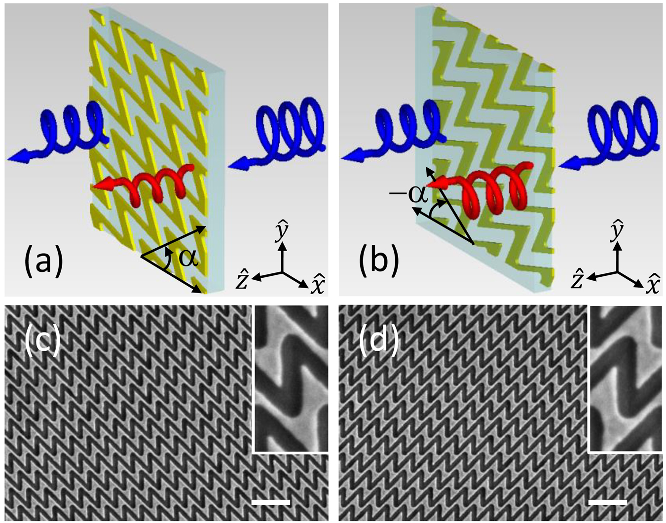
Schematic of bidirectional transmission of planar sawtooth chiral metasurfaces.
(a) and (b) Transmission of circularly polarized light (RCP, +) for (a) forward and (b) backward (flipping sample along the
We use the Jones matrix approach to model the propagation of waves for our Au sawtooth metasurface-sapphire system [28]. (More details about the Jones matrix for the metasurface-sapphire system can be found in Section 1 of the Supplementary Material.) For waves propagating in the positive
where
for the forward (F) incidence and
for the backward (B) incidence, where l = N/N−1 denotes our planar N-/И-type Au sawtooth nanoarray chiral metasurface.
To obtain the transmission phase, we add a birefringent plate/slab (a-cut sapphire) to the metasurface as reported earlier for circular phase-dichroism measurements [37]. As sapphire is a uniaxial birefringent crystal, the refractive index for the
E
field component along the extraordinary (optical) axis (
where
Furthermore, the transmittance of the metasurface-sapphire system can then be expressed in oscillating cosine functions as:
where
are the transmission phases. Note that for unitary transfer matrix
It is clear from Eq. (5) that the transmittance for the Au sawtooth metasurface-sapphire system exhibits BI oscillations. However, as we are interested in the relative measurements to eliminate systematic errors and the numerical aperture (NA) effects of the optical system [44], the transmission phase for the metasurface-sapphire system is better characterized by the relative phase w.r.t. that of the sapphire slab, i.e.
Furthermore, according to the Lorentz Reciprocity Lemma theorem [28],
Moreover, as the “atoms” N and И for our metasurfaces are mirror images of each other and 2D chiral [45], the transmission coefficients of the planar N- and И-type Au sawtooth metasurfaces satisfy
Note that the relative transmission phase defined by Eqs. (8) and (9) for the Au sawtooth metasurface-sapphire system depends only on the transmission coefficients of the metasurface
Then, it can be shown from Eq. (8) that:
for
for
for
3 Experiment
3.1 Fabrication of the Au sawtooth nanoarray metasurface
Following the procedures reported earlier [37], our planar Au sawtooth nanoarray metasurface sample was fabricated by using first an e-beam evaporation technique to deposit a 30 nm Au film onto a nonbirefringent substrate and then a focus ion-beam technique to direct-write 50 × 50 μm2 sawtooth nanohole-array patterns onto the Au film. Figure 1c and d show, respectively, SEM images of the planar (30 nm thick) N- and И-type Au sawtooth metasurfaces with 450 nm lattice spacing’s in both the horizontal and vertical directions for the visible range. The insets of Figure 1c and d are enlarged images of the unit cells for the Au sawtooth metasurfaces. Note that the Au sawtooth nanoarrays have a half lattice horizontal shift between alternate rows so that each Au sawtooth nanoarray is disconnected from the above and below neighboring Au sawtooth nanoarrays.
3.2 Bidirectional transmission and phase measurements
Figure 2a shows the transmittance, obtained using the procedures reported earlier [37], of our Au sawtooth metasurface placed on an a-cut sapphire slab, thickness L = 2 mm, for the forward (left column) and backward (right column) directions with a base angle α = 30°/−30° and −α = −30°/30°, respectively. It is clear that the transmittance for the sapphire slab and the N-/И-type Au sawtooth metasurface all exhibit BI oscillations due to the phase difference
where
with
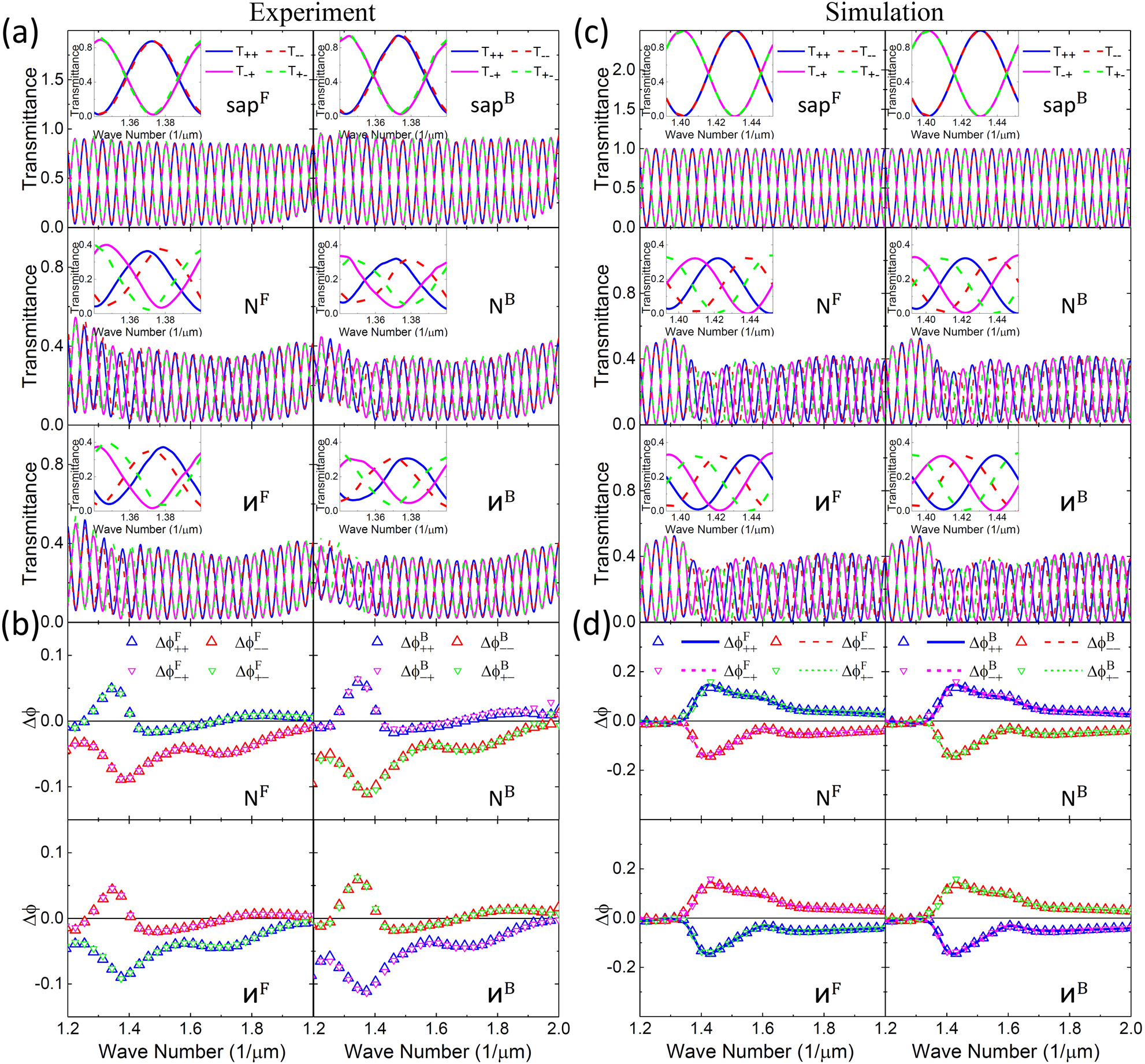
Bidirectional transmittance and transmission phase.
(a) and (b) Measurements of transmittance and transmission phase for circularly polarized incidence for forward (left column)/backward (right column) direction of the metasurface systems placed on the top of an L = 2 mm a-cut sapphire birefringence crystal slab with base angle α = 30°/−30° for the forward and −α = −30°/30° for the backward directions. The insets are the transmittance on an expanded scale for about one birefringence interference period. Open triangles in (b) are transmission phase w.r.t. the a-cut sapphire obtained from Eq. (15). (c) and (d) Corresponding transmittance and transmission phase from simulations for the experimental results in (a) and (b). Symbols are transmission phases obtained from the peak shift method using Eq. (15) and curves are calculations using Eq. (7).
To obtain more robust results, we characterize the transmission phase simply by the phase shift w.r.t. that of the sapphire slab to cancel out the systematic errors of the optical system [44]. Thus, the transmission phase of the planar Au sawtooth metasurface can be evaluated at the peaks/troughs (peak shift method) by:
Note that the transmission phase
Figure 2b shows the transmission phase
3.3 Asymmetric transmission phase
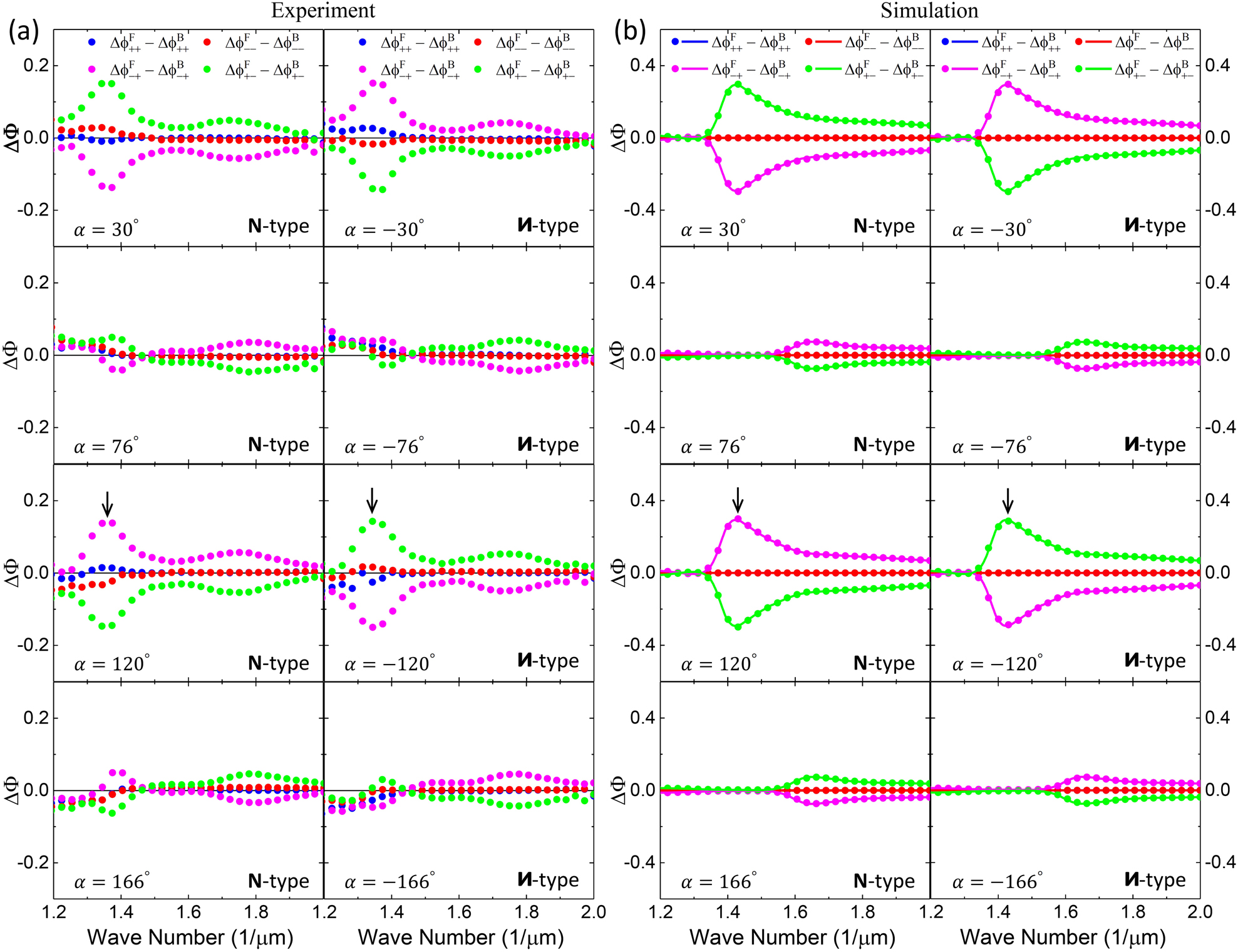
Figure 3 shows the experimental results of the bidirectional transmission phase difference, defined in Eq. (10) as the ATP
Asymmetric transmission phase.
(a) Experimental results of ATP for the N- and
Controllable asymmetric transmission and transmission phase.
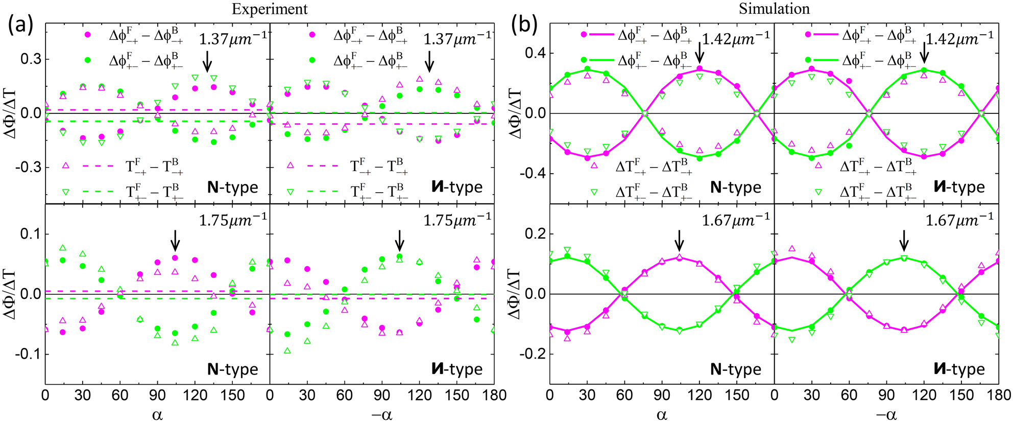
(a) Results of ATP (solid dots) at wavenumbers 1.37 μm−1 and 1.75 μm−1 and AT (open triangles) at corresponding wavenumbers for the N- and
The controllability of the ATP for the N-/И-type Au sawtooth metasurface-sapphire system can also apply to the AT (
To further elucidate our approach on other systems, we fabricate achiral planar and complementary double-layer plasmonic metasurfaces and obtain the AT and ATP as described in Section 7 of the Supplementary Material. The results show similar tunable behaviors as the sawtooth metasurfaces above with the add-on sapphire slab despite the original “atoms” of the metasurfaces being achiral. Moreover, the response for the ATP can be much larger than that of the AT for the complementary double-layer metasurface. These results demonstrate the advantage of using the add-on sapphire slab to control the chiral properties of metasurfaces/metamaterials. (Detailed discussion about the application of our approach to achiral metasurfaces can be found in Section 7 of the Supplementary Material.)
To conclude, the ATP is more robust than the AT as the phase is not sensitive to fluctuations of the signal amplitude while the transmittance is directly affected. Thus the ATP serves as a good alternative, if not complementing the AT, for the characterization of asymmetric transport of chiral materials. Furthermore, our results demonstrate well the tunability advantage of adding the sapphire slab to metasurfaces. Note that the transmission efficiency of the metasurface-sapphire system could be improved by replacing the Au with dielectric materials for the metasurface [40, 41]. Moreover, the sapphire slab is applicable in the optical wavelengths as it is transparent from the ultraviolet to the infrared spectrum. Furthermore, the uniaxial birefringent sapphire slab used in this work can be replaced by a biaxial birefringent material or any substrate inscribed with various anisotropies to further increase the degrees of freedom in wave controls and manipulations.
4 Simulation of Au sawtooth metasurface-sapphire system
4.1 Full-wave simulation
To support our approach in using the BI approach for characterizing ATP with tunable responses in chiral metasurface we perform full-wave simulations to cross-check our experimental results. Instead of simulating the whole Au sawtooth metasurface-sapphire chiral system, we follow the approach used for the transmission phase as reported recently [37]. Firstly, the Jones matrix
4.2 Simulation results
Figure 2c and d show the transmittance and transmission phase of the N- and И-type Au sawtooth metasurface-sapphire systems for the forward and backward incidence with base angles α corresponding to those of the experiments as shown in Figure 2a and b. The overall transmittance, also in expanded scales in the insets, resembles the experimental results very well. Similarly, the transmission phase (relative to that of the sapphire) exhibits very similar responses as the experiment.
Figure 3b shows the corresponding simulation results of the ATP for the experimental results for various base angles α as shown in Figure 3a. The simulations agree very well with the experiments except that the local maximum at 1/λ ∼ 1.37 μm−1 (indicated by the black arrows) observed in the experiment is now shifted to 1/λ ∼ 1.42 μm−1 due to the substrate effect and also the physical parameters (dimensions of the Au sawtooth nanoarrays and dielectric constants of the materials) used in the simulations may not match those of the experiment perfectly. Note that the simulation results obtained by the peak shift method using Eqs. (10) and (15) (symbols) are the same as those obtained directly from calculations using Eqs. (7) and (10) (solid curves), supporting the use of the peak shift method for the experiments. Note also that the second local maximum at 1/λ ∼ 1.75 μm−1 observed in the experiment as shown in Figure 3a is not as obvious in the simulations for the chosen base angles. However, it is noticeable at the base angle α ∼ 14°/104° with a shift to 1/λ ∼ 1.67 μm−1 as shown in Figure 10 of the Supplementary Material.
Figure 4b summarizes the simulated results for the ATP of the N- and И-type Au sawtooth metasurface-sapphire systems at the local maxima, 1/λ ∼ 1.42 μm−1 and 1/λ ∼ 1.67 μm−1, as a function of the base angle. The oscillatory dependence agrees very well with the experimental results shown in Figure 4a despite that the angles for the local maxima are slightly shifted and also the magnitudes are larger. Overall, the simulations confirm our experimental results and support the use of the sapphire slab as a tunable element to control the ATP, as well as the traditional AT.
5 Conclusions
We propose a novel approach in the characterization of planar chiral metasurface with a controllable asymmetric transmission phase using a simple interference technique by adding a birefringent crystal, here a uniaxial a-cut sapphire slab, to the metasurface. To demonstrate our approach, we measure the ATP of N-/И-type Au sawtooth nanoarray chiral metasurface placed on the sapphire slab as a function of the controllable base angle between the nanoarray of the metasurface and the optical axis of the sapphire slab. To cross-check our approach, we also perform full-wave simulations of our Au sawtooth metasurface-sapphire system and obtain good agreement with the experiments. The tunability approach by adding a birefringent substrate can also be applied to the traditional AT. Importantly, the metasurface does not have to be fabricated directly on the birefringent substrate and the add-on birefringent plate can be incorporated as a lens or a filter for a measuring device. Thus our approach is flexible and nondestructive, offering great potentials in optical communication, imaging, and remote sensing applications.
Supplementary material
The supplementary materials are available for some supporting information. Section 1 gives the Jones matrix for the metasurface-sapphire system; Section 2 shows the experimental transmittance and transmission phase; Section 3 presents the transmittance and asymmetric transmission of Au sawtooth metasurface-sapphire system; Section 4 explains the resonances of Au sawtooth metasurface; Section 5 provides more results for the asymmetric transmission phase of Au sawtooth metasurface-sapphire system; Section 6 demonstrates the asymmetric transmission of Au sawtooth metasurface-sapphire system; Section 7 shows applications to achiral metasurfaces.
-
Author contribution: Ranran Zhang is a postdoctoral researcher at the Physics Department of the College of Mathematics and Physics, Qingdao University of Science and Technology (QUST). This project was under the join-supervision of Profs. Q. Zhao and X. Wang at QUST, and Profs. J. Li and W. Y. Tam at the Hong Kong University of Science and Technology (HKUST).
-
Research funding: W. X. acknowledges support from the National NSFC (11874232, 12174211); T. W. Y. acknowledges support from the Hong Kong RGC grant AoE P-02/12 and the support from the College of Mathematics and Physics at QUST; L. J. and T. W. Y. acknowledge support from the Hong Kong RGC grant C6013-18GF.
-
Conflict of interest statement: The authors declare no conflict of interest.
References
[1] R. S. Kshetrimayum, “A brief introduction to metamaterials,” IEEE Potentials, vol. 23, pp. 44–46, 2004.10.1109/MP.2005.1368916Suche in Google Scholar
[2] N. Engheta and W. Z. Richard, Metamaterials: Physics and Engineering Explorations, New York, John Wiley & Sons, 2006.10.1002/0471784192Suche in Google Scholar
[3] S. Zouhdi, S. Ari, and P. V. Alexey, Metamaterials and Plasmonics: Fundamentals, Modeling, Applications, New York, Springer, 2008.Suche in Google Scholar
[4] C. L. Holloway, E. F. Kuester, J. A. Gordon, J. O’Hara, J. Booth, and D. R. Smith, “An overview of the theory and applications of metasurfaces: the two-dimensional equivalents of metamaterials,” IEEE Antenn. Propag. Mag., vol. 54, pp. 10–35, 2012. https://doi.org/10.1109/map.2012.6230714.Suche in Google Scholar
[5] A. V. Kildishev, A. Boltasseva, and V. M. Shalaev, “Planar photonics with metasurfaces,” Science, vol. 339, p. 1232009, 2013. https://doi.org/10.1126/science.1232009.Suche in Google Scholar PubMed
[6] N. F. Yu and F. Capasso, “Flat optics with designer metasurfaces,” Nat. Mater., vol. 13, pp. 139–150, 2014. https://doi.org/10.1038/nmat3839.Suche in Google Scholar PubMed
[7] L. Zhang, S. T. Mei, K. Huang, and C. W. Qiu, “Advances in full control of electromagnetic waves with metasurfaces,” Adv. Opt. Mater., vol. 4, pp. 818–833, 2016. https://doi.org/10.1002/adom.201500690.Suche in Google Scholar
[8] Z. L. Li, S. H. Yu, and G. X. Zheng, “Advances in exploiting the degrees of freedom in nanostructured metasurface design: from 1 to 3 to more,” Nanophotonics, vol. 9, pp. 3699–3731, 2020. https://doi.org/10.1515/nanoph-2020-0127.Suche in Google Scholar
[9] H. H. Hsiao, C. H. Chu, and D. P. Tsai, “Fundamentals and applications of metasurfaces,” Small Methods, vol. 1, p. 1600064, 2017. https://doi.org/10.1002/smtd.201600064.Suche in Google Scholar
[10] A. Li, S. Singh, and D. Sievenpiper, “Metasurfaces and their applications,” Nanophotonics, vol. 7, pp. 989–1011, 2018. https://doi.org/10.1515/nanoph-2017-0120.Suche in Google Scholar
[11] N. Yu, P. Genevet, M. A. Kats, et al.., “Light propagation with phase discontinuities: generalized laws of reflection and refraction,” Science, vol. 6051, pp. 333–337, 2011. https://doi.org/10.1126/science.1210713.Suche in Google Scholar PubMed
[12] L. L. Huang, X. Z. Chen, H. Muhlenbernd, et al.., “Dispersionless phase discontinuities for controlling light propagation,” Nano Lett., vol. 12, pp. 5750–5755, 2012. https://doi.org/10.1021/nl303031j.Suche in Google Scholar PubMed
[13] M. Khorasaninejad, W. T. Chen, R. C. Devlin, J. Oh, A. Y. Zhu, and F. Capasso, “Metalenses at visible wavelengths: diffraction-limited focusing and subwavelength resolution imaging,” Science, vol. 6290, pp. 1190–1194, 2016. https://doi.org/10.1126/science.aaf6644.Suche in Google Scholar PubMed
[14] S. M. Wang, P. C. Wu, V. C. Su, et al.., “A broadband achromatic metalens in the visible,” Nat. Nanotechnol., vol. 13, pp. 227–232, 2018. https://doi.org/10.1038/s41565-017-0052-4.Suche in Google Scholar PubMed
[15] H. M. Leung, W. S. Gao, R. R. Zhang, et al.., “Exceptional point-based plasmonic metasurfaces for vortex beam generation,” Opt. Express, vol. 28, pp. 503–510, 2020. https://doi.org/10.1364/oe.28.000503.Suche in Google Scholar PubMed
[16] M. Piccardo and A. Ambrosio, “Arbitrary polarization conversion for pure vortex generation with a single metasurface,” Nanophotonics, vol. 10, pp. 727–732, 2021. https://doi.org/10.1515/9783110710687-060.Suche in Google Scholar
[17] M. A. Naveed, M. A. Ansari, I. Kim, et al.., “Optical spin-symmetry breaking for high-efficiency directional helicity-multiplexed metaholograms,” Microsyst. Nanoeng., vol. 7, p. 5, 2021. https://doi.org/10.1038/s41378-020-00226-x.Suche in Google Scholar PubMed PubMed Central
[18] X. Liang, L. Deng, X. Shan, et al.., “Asymmetric hologram with a single-size nanostructured metasurface,” Opt. Express, vol. 29, pp. 19964–19974, 2021. https://doi.org/10.1364/oe.430217.Suche in Google Scholar PubMed
[19] S. M. Kamalia, E. Arbabia, A. Arbabi, and A. Faraon, “A review of dielectric optical metasurfaces for wavefront control,” Nanophotonics, vol. 7, pp. 1041–1068, 2018. https://doi.org/10.1515/nanoph-2017-0129.Suche in Google Scholar
[20] J. Hu, S. Bandyopadhyay, Y. H. Liu, and L. Y. Shao, “A review on metasurface: from principle to smart metadevices,” Front. Physiol., vol. 8, p. 586087, 2021. https://doi.org/10.3389/fphy.2020.586087.Suche in Google Scholar
[21] Q. He, S. L. Sun, and L. Zhou, “Tunable/reconfigurable metasurfaces: physics and applications,” Research, vol. 2019, pp. 4216–4223, 2019. https://doi.org/10.34133/2019/1849272.Suche in Google Scholar PubMed PubMed Central
[22] S. M. Kamalia, E. Arbabia, A. Arbabi, Y. Horie, and A. Faraon, “Highly tunable elastic dielectric metasurface lenses,” Laser Photon. Rev., vol. 10, pp. 1002–1008, 2016. https://doi.org/10.1002/lpor.201600144.Suche in Google Scholar
[23] Z. Q. Miao, Q. Wu, X. Li, et al.., “Widely tunable terahertz phase modulation with gate-controlled graphene metasurfaces,” Phys. Rev. X, vol. 5, p. 041027, 2015. https://doi.org/10.1103/physrevx.5.041027.Suche in Google Scholar
[24] Y. Horie, A. Arbabi, E. Arbabi, S. M. Kamali, and A. Faraon, “High-speed, phase-dominant spatial light modulation with silicon-based active resonant antennas,” ACS Photonics, vol. 5, pp. 1711–1717, 2018. https://doi.org/10.1021/acsphotonics.7b01073.Suche in Google Scholar
[25] B. N. Wang, J. F. Zhou, T. Koschny, M. Kafesaki, and C. M. Soukoulis, “Chiral metamaterials: simulations and experiments,” J. Opt. A, vol. 11, p. 114003, 2009. https://doi.org/10.1088/1464-4258/11/11/114003.Suche in Google Scholar
[26] S. Yoo and Q.-H. Park, “Metamaterials and chiral sensing: a review of fundamentals and applications,” Nanophotonics, vol. 8, pp. 249–261, 2019. https://doi.org/10.1515/nanoph-2018-0167.Suche in Google Scholar
[27] V. A. Fedotov, A. S. Schwanecke, and N. I. Zheludev, “Asymmetric transmission of light and enantiomerically sensitive plasmon resonance in planar chiral nanostructures,” Nano Lett., vol. 7, pp. 1996–1999, 2007. https://doi.org/10.1021/nl0707961.Suche in Google Scholar
[28] C. Menzel, C. Helgert, C. Rockstuhl, et al.., “Asymmetric transmission of linearly polarized light at optical metamaterials,” Phys. Rev. Lett., vol. 104, p. 253902, 2010. https://doi.org/10.1103/physrevlett.104.253902.Suche in Google Scholar PubMed
[29] D. Frese, Q. S. Wei, Y. T. Wang, L. L. Huang, and T. Zentgraf, “Nonreciprocal asymmetric polarization encryption by layered plasmonic metasurfaces,” Nano Lett., vol. 19, pp. 3976–3980, 2019. https://doi.org/10.1021/acs.nanolett.9b01298.Suche in Google Scholar PubMed
[30] Y. Zhao, M. A. Belkin, and A. Alù, “Twisted optical metamaterials for planarized ultrathin broadband circular polarizers,” Nat. Commun., vol. 3, p. 870, 2012. https://doi.org/10.1038/ncomms1877.Suche in Google Scholar PubMed
[31] Y. Chen, J. Gao, and X. D. Yang, “Direction-controlled bifunctional metasurface polarizers,” Laser Photonics Rev., vol. 12, p. 1800198, 2018. https://doi.org/10.1002/lpor.201800198.Suche in Google Scholar
[32] T. T. Kim, S. S. Oh, H. D. Kim, et al.., “Electrical access to critical coupling of circularly polarized waves in graphene chiral metamaterials,” Sci. Adv., vol. 3, p. 1701377, 2017. https://doi.org/10.1126/sciadv.1701377.Suche in Google Scholar PubMed PubMed Central
[33] S. D. Liu, J. Y. Liu, Z. L. Cao, J. L. Fan, and D. Y. Lei, “Dynamic tuning of enhanced intrinsic circular dichroism in plasmonic stereo-metamolecule array with surface lattice resonance,” Nanophotonics, vol. 9, pp. 3419–3434, 2020. https://doi.org/10.1515/nanoph-2020-0130.Suche in Google Scholar
[34] Y. Y. Huang, Z. H. Yao, F. R. Hu, et al.., “Tunable circular polarization conversion and asymmetric transmission of planar chiral graphene-metamaterial in terahertz region,” Carbon, vol. 119, pp. 305–313, 2017. https://doi.org/10.1016/j.carbon.2017.04.037.Suche in Google Scholar
[35] J. X. Zhou, Y. Y. Wang, M. J. Lu, J. Ding, and L. Zhou, “Giant enhancement of tunable asymmetric transmission for circularly polarized waves in a double-layer graphene chiral metasurface,” RSC Adv., vol. 9, p. 33775, 2019. https://doi.org/10.1039/c9ra05760a.Suche in Google Scholar PubMed PubMed Central
[36] R. R. Zhang, Q. L. Zhao, X. Wang, W. S. Gao, J. Li, and W. Y. Tam, “Measuring circular phase-dichroism of chiral metasurface,” Nanophotonics, vol. 8, pp. 909–920, 2019. https://doi.org/10.1515/nanoph-2019-0061.Suche in Google Scholar
[37] R. R. Zhang, Q. L. Zhao, X. Wang, J. Li, and W. Y. Tam, “Circular phase-dichroism of chiral metasurface using birefringent interference,” Nano Lett., vol. 20, pp. 2681–2687, 2020. https://doi.org/10.1021/acs.nanolett.0c00311.Suche in Google Scholar PubMed
[38] W. S. Gao, C. Y. Ng, H. M. Leung, Y. H. Li, H. Chen, and W. Y. Tam, “Circular dichroism in single layered gold sawtooth gratings,” J. Opt. Soc. Am. B, vol. 29, pp. 3021–3026, 2012. https://doi.org/10.1364/josab.29.003021.Suche in Google Scholar
[39] G. X. Li, M. Kang, S. M. Chen, et al.., “Spin-enabled plasmonic metasurfaces for manipulating orbital angular momentum of light,” Nano Lett., vol. 13, pp. 4148–4151, 2013. https://doi.org/10.1021/nl401734r.Suche in Google Scholar PubMed
[40] Z. J. Ma, Y. Li, Y. Li, et al.., “All-dielectric planar chiral metasurface with gradient geometric phase,” Opt. Express, vol. 26, pp. 6067–6078, 2018. https://doi.org/10.1364/oe.26.006067.Suche in Google Scholar
[41] M. R. Akram, M. Q. Mehmood, X. G. Bai, R. H. Jin, M. Premaratne, and W. R. Zhu, “High efficiency ultrathin transmissive metasurfaces,” Adv. Opt. Mater., vol. 7, p. 1801628, 2019. https://doi.org/10.1002/adom.201801628.Suche in Google Scholar
[42] M. J. Wang and Z. Z Zhai, “Wide-angle circular polarization converter based on a metasurface of Z-shaped unit cells,” Front. Physiol., vol. 8, p. 527394, 2020. https://doi.org/10.3389/fphy.2020.527394.Suche in Google Scholar
[43] S. S. Oh and O. Hess, “Chiral metamaterials: enhancement and control of optical activity and circular dichroism,” Nano Converg., vol. 2, p. 24, 2015. https://doi.org/10.1186/s40580-015-0058-2.Suche in Google Scholar PubMed PubMed Central
[44] Q. L. Zhao, T. Y. Yung, X. Wang, and W. Y. Tam, “Correction of numerical aperture effect on reflection phase measurement using thick-gap Fabry Perot etalon,” Appl. Opt., vol. 15, pp. 4392–4397, 2017. https://doi.org/10.1364/ao.56.004392.Suche in Google Scholar PubMed
[45] C. Menzel, C. Rockstuhl, and L. Falk, “Advanced Jones calculus for the classification of periodic metamaterials,” Phys. Rev. A, vol. 82, p. 053811, 2010. https://doi.org/10.1103/physreva.82.053811.Suche in Google Scholar
[46] T. K. Yung, Q. L. Zhao, W. S. Gao, X. Wang, and W. Y. Tam, “Measurement of reflection phase using thick-gap Fabry–Perot etalon,” Appl. Opt., vol. 55, pp. 7301–7306, 2016. https://doi.org/10.1364/ao.55.007301.Suche in Google Scholar PubMed
Supplementary Material
The online version of this article offers supplementary material (https://doi.org/10.1515/nanoph-2021-0558).
© 2021 Ranran Zhang et al., published by De Gruyter, Berlin/Boston
This work is licensed under the Creative Commons Attribution 4.0 International License.
Artikel in diesem Heft
- Frontmatter
- Reviews
- A review of terahertz phase modulation from free space to guided wave integrated devices
- Intelligent on-demand design of phononic metamaterials
- Light activation of 3D-printed structures: from millimeter to sub-micrometer scale
- Research Articles
- Unveiling radial breathing mode in a particle-on-mirror plasmonic nanocavity
- Controlling asymmetric transmission phase in planar chiral metasurfaces
- Rayleigh anomaly-enabled mode hybridization in gold nanohole arrays by scalable colloidal lithography for highly-sensitive biosensing
- Enhanced terahertz detection of multigate graphene nanostructures
- The anisotropic broadband surface plasmon polariton and hot carrier properties of borophene monolayer
- Probing higher order optical modes in all-dielectric nanodisk, -square, and -triangle by aperture type scanning near-field optical microscopy
- Cascaded microsphere-coupled surface-enhanced Raman spectroscopy (CMS-SERS) for ultrasensitive trace-detection
- Morphology adjustable microlens array fabricated by single spatially modulated femtosecond pulse
- Design framework for polarization-insensitive multifunctional achromatic metalenses
- Electro-optically modulated lossy-mode resonance
- Double Rabi splitting in methylene blue dye-Ag nanocavity
- Broadband high-efficiency near-infrared graphene phase modulators enabled by metal–nanoribbon integrated hybrid plasmonic waveguides