Conditions for establishing the “generalized Snell’s law of refraction” in all-dielectric metasurfaces: theoretical bases for design of high-efficiency beam deflection metasurfaces
-
Siyuan Shen

 und
Heping Tan
und
Heping Tan

Abstract
The generalized Snell’s law dictates that introducing a phase gradient at the interface of two media can shape incident light and achieve anomalous reflection or refraction. However, when the introduced phase gradient is realized via the scattering of nanoparticles in the metasurfaces, this law needs to be modified; certain conditions need to be met when the law is established. We present the conditions for establishing the “generalized Snell’s law of refraction” in all-dielectric metasurfaces under the incidence of different polarized light. These conditions can provide theoretical bases for the subsequent design of high-efficiency beam deflection metasurfaces. The relationship between the highest achievable anomalous refraction efficiency and the number of nanoparticles within one period of the metasurface is also summarized. In addition, the generalized refraction should not depend on the polarization states of incident light; however, the previous realization conditions of anomalous refraction were sensitive to the polarization states. Thus, conditions for establishing the polarization-independent generalized Snell’s law of refraction in all-dielectric metasurfaces are presented.
1 Introduction
Conventional optical devices rely on the phase shifts accumulated during the propagation of light to shape light beams [1]. However, the phase discontinuities introduced by two-dimensional (2D) nanoparticle arrays (metasurfaces) disrupt the dependence of light on the phase accumulation during propagation; this also enables the metasurfaces to locally modify the phase, polarization state, and intensity of light beams at the subwavelength scale [2]. Currently, it is possible to manufacture metasurfaces with nanometer-scale precision and a wide range of physical parameters and materials, which provides almost any amount of freedom for the design of new optical components [3], [4], [5]. Among these, all-dielectric metasurfaces have attracted extensive attention owing to their high efficiency and low loss [6].
A basic function of metasurfaces is the realization of light beam deflection (i.e., to reflect or refract incident light to the desired direction). Over recent years, some previous studies have studied the conditions required for metasurfaces to realize efficient light beam deflection. For instance, in 2011, Yu et al. [1] proposed generalized laws of reflection and refraction and showed that anomalous reflection can be observed when metallic antennas on silicon within one period of the metasurface array have a linear phase change along the interface. In 2020, Rousseau et al. [7] reported that the above-mentioned generalized laws of refraction and reflection have to be modified to describe the propagation of light through metasurfaces composed of diffractive elements. They also theoretically proved that generalized reflection or refraction can only be achieved when nanoparticles within one period of the metasurface introduce a phase jump with a slope of 2π/(the metasurface period). At this time, the form of the generalized laws of reflection and refraction are completely transformed into the grating diffraction equations. However, the conditions to achieve generalized reflection or refraction, as stated in the above literature, remain unclear. Furthermore, the research on designing metasurfaces based on the generalized Snell’s law has not yielded a specific rule for designing efficient beam deflection metasurfaces. For example, previous studies [1, 8], [9], [10], [11], [12], [13], [14], [15], [16], [17], [18] have indicated that the nanoparticles within one period of the metasurface array must introduce a phase gradient with a linear distribution in the 2π range in order to achieve anomalous refraction or reflection. However, the phase gradients along the interface introduced by the actual selected nanoparticles failed to reach 2π in literature [8], [9], [10], [11], [12], [13], [14], [15], [16], [17]. The phase gradients in literature [18] reached such a range; however, the efficiency of anomalous refraction they realized was only greater than 60%. Therefore, according to the above-discussed literature and analysis, the conditions that metasurfaces need to meet in order to achieve generalized reflection or refraction have not been unified nor clarified thus far. It is, therefore, necessary to further explore and analyze the specific principles for designing efficient beam deflection metasurfaces.
For the development and design of beam steering metasurfaces, it is also necessary to understand the maximum achievable value of anomalous refraction (reflection) efficiency of the metasurfaces, which can be expressed as transmission (reflection) efficiency in the anomalous refraction (reflection) direction/total transmission (reflection) efficiency. However, few studies have focused on the efficiency of anomalous reflection or refraction achieved by metasurfaces. In 1989, a diffraction efficiency formula for multi-level phase gratings was proposed [19]; it served as a basis for subsequent research on the anomalous reflection or refraction efficiency. Subsequently, in 2021, Isić et al. [5] formulated a theoretical model for the beam deflection efficiency in reflective metasurfaces, based on the scalar diffraction theory [20], Fourier optics theory [21], and temporal coupled-mode theory [22]. To the best of our knowledge, none of the previous studies have focused on the efficiency of beam deflection in transmissive metasurfaces.
Based on the background, this study aims to further study and analyze the establishment conditions for the generalized Snell’s law of refraction in transmissive metasurfaces under the incidence of different polarized light, to provide specific rules for designing efficient beam deflection metasurfaces and to give the highest achievable efficiency value of anomalous refraction. We emphasize that we are currently only concerned with metasurfaces composed by the unit cell containing one nanoparticle, and this study assumes that the interaction between the nanoparticles and light is limited within the particles and is not affected by the scattering of the surrounding particles [1, 2].
2 Theory
The metasurfaces explored in this study are composed of all-dielectric nanoparticles, whose Jones matrix acts as a linear birefringent, unitary matrix. Over recent years, this type of metasurfaces has emerged as the most widely studied and most common all-dielectric metasurfaces. They can be realized using rectangular or elliptical dielectric nanopillars that exhibit birefringence (Figure 1). The transverse section of the dielectric nanopillars features two perpendicular symmetry axes; therefore, two modes related to the polarization states of incident light are expected to propagate with different indices in the pillars. Thus, the pillars can behave as wave plates [23]. For the pillars in Figure 1, the Jones matrix can be expressed as [2, 24], [25], [26], [27].
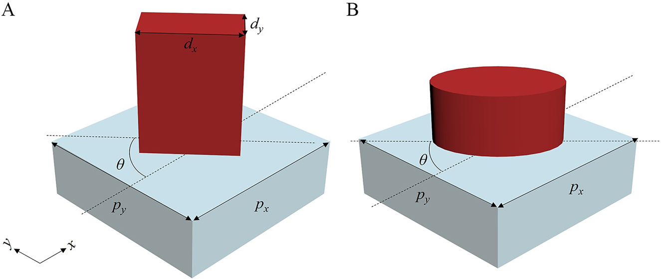
Dielectric nanopillar unit structure.
(A) Rectangular. (B) Elliptical nanopillars.
Here, R(θ) is a 2 × 2 rotation matrix, and θ denotes the rotation angle of the pillar element (Figure 1). ϕ x represents the phase change introduced by the nanopillars to the x-polarized (0° linear polarized) incident light, and ϕ y shows the phase change introduced by the nanopillars to the y-polarized (90° linear polarized) incident light. Either these phase changes can be independently controlled by designing the geometric dimensions of the nanopillars (the phase change introduced using this method is termed as the propagation phase) or by adjusting the rotation angles of the nanopillars (the phase change introduced using this method is termed as the geometric phase). Eq. (1) implies that the nanopillars only regulate the phase of incident light but not the amplitude. It also implies two restrictions [23]: the Jones matrix must be unitary and linearly birefringent.
The beam deflection metasurfaces studied are composed of periodic supercells. The basic structure of the supercell is shown in Figure 2A. Each supercell is composed of A × B dielectric nanopillar units. Each nanopillar unit, l, can introduce a phase variation, ϕ
xl
, to the x-polarized incident light and a phase variation, ϕ
yl
, to the y-polarized incident light. The periods of each unit are p
x
along the x-direction and p
y
along the y-direction. As the metasurfaces are periodic arrays, each item in the Jones matrix of the nanopillars should also be periodic. In other words, for any nanopillar l, ϕ
x(l + A) = ϕ
xl
, ϕ
y(l + B) = ϕ
yl
. Figure 2B simplifies the metasurface grating structure with a 2D grid. The position of the origin is depicted in Figure 2B. Each grid represents a nanopillar, and the position is represented by (a, b), where a, b are integers and
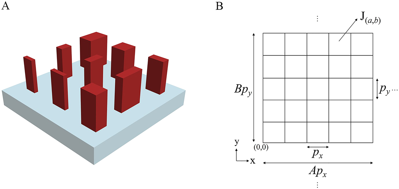
Basic structure of supercells of the beam deflection metasurfaces and simplified representation of the 2D grid of the metasurface grating structure.
(A) Basic structure of the supercells. (B) Simplified representation of the 2D grid of the metasurface grating.
Here, θ (a,b), ϕ x(a,b), and ϕ y(a,b) represent the rotation angle of the nanopillar, phase variation introduced to the x-polarized incident light, and phase variation introduced to the y-polarized incident light at the position (a, b), respectively.
According to Eq. (2), we can obtain the expression of the Jones matrix at each position of the metasurface:
Here,
where
Here, J (m,n) is given by the projection of J (x,y) onto the (m, n) order (the (m, n) term in the Fourier series of the function J (x,y)), which also represents the (m, n)th transmission coefficient of transmitted light.
On substituting Eq. (4) in Eq. (5), we can obtain
where
3 Results and discussion
3.1 Conditions for establishing the generalized law of refraction under the incidence of different polarized light
Using Eq. (6), the (m, n)th transmission coefficient of the transmitted light can be calculated. Subsequently, the anomalous refraction efficiency of the transmitted wave to the (m, n)th order can be obtained. It should be emphasized that, because the metasurfaces are composed of nanopillars whose Jones matrix is a linear birefringent, unitary matrix, the responses of the metasurfaces to different polarized light vary; consequently, the metasurfaces shape different polarized light in different manners. Thus, J
(m,n) is a function related to the polarization states of the incident light; for a certain polarization state of the incident light
where
Here, we analyze the cases under the incidence of arbitrary linear polarized light, left-handed circularly polarized light, and right-handed circularly polarized light separately.
Arbitrary linear polarized light:
On substituting Eq. (2) and
According to Eq. (9), we can obtain the relationship between the highest achievable anomalous refraction efficiency and m/A, n/B when the incident light is diffracted through the metasurfaces to the (m, n)th order (Figure 3A). It can be seen that the higher the diffraction order and the smaller the number of nanoparticles in a single supercell of the metasurface, the lower the diffraction efficiency, and the diffraction efficiency cannot reach 100%. When
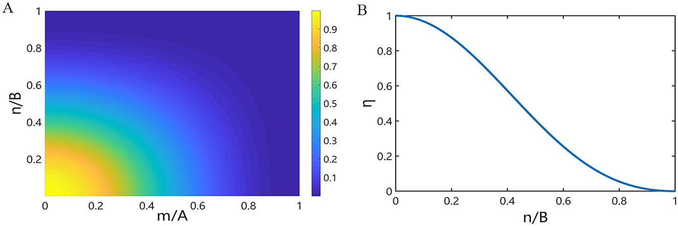
(A) The relationship between the highest achievable anomalous refraction efficiency and m/A, n/B when the incident light is diffracted to the (m, n)th order. (B) The relationship between the highest achievable anomalous refraction efficiency and n/B when the incident light is diffracted to the (0, n)th order and when the metasurface has only one phase gradient along a single direction.
According to Eq. (8), a special case can be observed. When ϕ x(a,b), ϕ x(c,d), ϕ y(a,b), and ϕ y(c,d) satisfy Eq. (10), irrespective of the values of θ (a,b) and θ (c,d), Eq. (8) always holds.
In addition, according to Eq. (8) and when the nanopillars in the metasurfaces have no rotation angles (i.e., the phase change (ϕ x , ϕ y ) introduced by each nanopillar in the metasurfaces to different polarized light only depends on the propagation phase), we obtain the conditions that the metasurfaces need to meet in order to realize the maximum value of I (m,n). In this case, Eq. (2) can be simplified as
On substituting Eq. (11) and
In particular, when the metasurface has only one phase gradient along a single direction, that is, A/B = 1, Eq. (12) can be simplified. For example, when A = 1, Eq. (12) can be simplified as
This is the most commonly designed structure for beam deflection transmissive metasurfaces [28], [29], [30], [31]. This type of metasurface typically fails to achieve high-order diffraction in the x-direction, and only the (0, 0)th diffraction is realized in the x-direction (i.e., m is equal to zero). This is because, in this case, generally, the supercell period of the metasurfaces in the x-direction is smaller than the wavelength of the incident wave. Thus, Eq. (9) can be simplified to
According to Eq. (14), we can obtain the relationship between the highest achievable efficiency and n/B when the incident light is diffracted through the metasurfaces to the (0, n)th order (Figure 3B). It can also be seen that the higher the diffraction order and the smaller the number of nanoparticles in a single supercell of the metasurface, the lower the diffraction efficiency, and the diffraction efficiency cannot reach 100%. When n/B ≤ 0.2573, the maximum achievable efficiency of the incident light diffracted through the metasurface to the (0, n)th order can be greater than 80%. Therefore, when the ratio of the diffraction order to the number of nanoparticles in a single supercell of the metasurface is no more than 0.2573, it is possible to design a metasurface with an anomalous refraction efficiency higher than 80%.
There are two particular cases:
In addition, we emphasize that, in this case, the generalized law of refraction is established under the condition that the phase change, ϕ x(a,b), introduced by the nanopillars over one period of the metasurface to the 0° linear polarized incident light satisfies Eq. (15). This is different to previous reports [8], [9], [10], [11], [12], [13], [14], [15], [16], [17], [18], where the nanopillars in one period of the metasurface need to introduce a linear distribution phase gradient in the 2π range.
Left-handed circularly polarized light:
On substituting Eq. (2) and
According to Eq. (19), a special case can be identified, that is, when ϕ x(a,b), ϕ x(c,d), ϕ y(a,b), and ϕ y(c,d) satisfy Eq. (10), irrespective of the values of θ (a,b) and θ (c,d), Eq. (19) always holds.
In addition, when the nanopillars in the metasurfaces have no rotation angles, on substituting Eq. (11) and
When the metasurface has only one phase gradient along a single direction, such as when A = 1, the same as the case under the incidence of any linear polarized light, when Eq. (13) is satisfied, I (m,n) reaches the maximum value, and the expression of the maximum value is simplified to Eq. (14).
According to Eq. (19) and when only changing the rotation angles of the nanopillars (which implies that the phase variation introduced by each nanopillar depends on the geometric phase alone), the conditions that the metasurfaces need to meet for realizing the maximum value of I (m,n) can be analyzed. In this case, Eq. (2) can be simplified as
On substituting Eq. (20) and
Right-handed circularly polarized light:
On substituting Eq. (2) and
According to Eq. (22), a special case can be identified, that is, when ϕ x(a,b), ϕ x(c,d), ϕ y(a,b), and ϕ y(c,d) satisfy Eq. (10), irrespective of the values of θ (a,b) and θ (c,d), Eq. (22) always holds.
In addition, when the nanopillars in the metasurface have no rotation angles, on substituting Eq. (11) and
When only changing the rotation angles of the nanopillars, on substituting Eq. (22) and
3.2 Verification
First, we prove the accuracy of the derivation process (i.e., the accuracy of the derived Eqs. (8), (9), (12), (15), (17), (19), (21), (22) and (23) when the model Eqs. (2), (6), (7) are established). We substitute Eq. (2) and
To verify the accuracy of Eqs. (12), (15), and (17), we substitute Eq. (11) and
To verify the accuracy of Eqs. (21) and (23), we substitute Eq. (20) and
To verify the accuracy of the established model (Eqs. (2), (6), and (7)) in design, we numerically simulate the anomalous refraction efficiency for different polarized incident light transmitted to the corresponding (m, n)th order after passing through the metasurfaces designed according to the above-mentioned equations, through FDTD Solutions. The basic dimensions of the metasurface unit cell are as follows: the periods in the x- and y-directions (i.e., p x and p y , respectively) are both 500 nm, the height of the nanopillars is 500 nm, the thickness of the substrate is 200 nm, the material of the nanopillars is set as the Si (Palik) model in FDTD, and the substrate material is set as SiO2 with a refractive index of 1.46. The specific verifications are detailed below.
First, we verify the case when the nanopillars have no rotation angles. As can be seen from Eqs. (12), (15), and (17), Eq. (12) contains Eqs. (15) and (17). Therefore, if Eq. (12) is satisfied, the anomalous refraction efficiency will reach the maximum value under the incidence of any polarized light. The case considered is A = 5, B = 5, and (m, n) = (1, 1), and the incident wavelength is 1300 nm. The phase variations that need to be introduced to different polarized incident light are presented in columns 4 of Table S3 calculated according to Eq. (12), by using the interior point method. We select the appropriate nanopillars according to the phase values. The cross-sections of the nanopillars selected are all square because, according to the data in columns 4 of Table S3, ϕ x(a,b) = ϕ y(a,b). The specific dimensions of the selected nanopillars, the transmission efficiency through the nanopillars under the incidence of 0° linear polarized light, and the actual phase variations introduced by the selected nanopillars are presented in Table S5, Supplementary material. Through the simulations in FDTD Solutions, we obtain the anomalous refraction efficiency of different polarized incident light transmitted to the (1, 1)th order through the metasurfaces composed by the selected nanopillars. The results are shown in Table S6 and Figure S2, Supplementary material. It is evident that the efficiency is basically consistent with the theoretically achievable maximum efficiency, obtained according to Eq. (9). The lower efficiency in certain cases is likely because the transmission efficiency through the nanopillars under the incidence of 0° linear polarized light is low (it also means that these cases fail to meet the limitations in Section 2, that is, the amplitude of the incident light is also adjusted by the nanopillars) and the scattering between the nanopillars interferes. We also provide the simulated corresponding electric field component field patterns, far-field electric field intensity as a function of the diffraction angle and far field electric field distribution respectively (Figures S3–S5, Supplementary material). The results prove the high anomalous refraction efficiency of different polarized incident light transmitted to the (1, 1)th order through the metasurfaces, and the deflection angle estimated (azimuth angle (φ) = 45°, zenith angle (θ) = 45°) in simulation (Figure S4) is also consistent with the theoretical value of which is derived from the well-known generalized Snell’s law (φ = θ = √2 * arcsin(λ/B/p y ) * 180/π = 44.3°). We also evaluate the case when A = 1, B = 5, (m, n) = (0, 1), the incident light is 1300 nm 0° linear polarized light, and nanopillars have no rotation angles. Here, we compare two design methods: designing the metasurface based on the phase data calculated according to Eq. (15) by using the interior point method and designing the metasurface based on the phase values linearly selected from 0 to 2π. The sizes of the selected nanopillars, the transmission efficiency of the 0° linear polarized incident light through the nanopillars, the calculated phase variations that need to be introduced by the nanopillars, and the actual phase variations introduced by the selected nanopillars of the two methods are presented in Table S7 and S8, Supplementary material. Through the simulations in FDTD Solutions, the anomalous refraction efficiency values for 0° linear polarized incident light passing through the two metasurfaces composed by the selected nanopillars to the (0, 1)th order are obtained. The results are shown in Table S9 and Figure S6, Supplementary material. As is evident, the efficiency obtained by the first design method is basically consistent with the one obtained according to Eq. (14) and higher than that obtained using the second design method. This also proves that in this case, the condition for the establishment of the generalized law of refraction is to satisfy Eq. (15), rather than introducing a linear distribution phase gradient within the range of 2π using the nanopillars in one period of the metasurface. We also provide the simulated Ex component of the transmitted light in the yz plane and far-field electric field intensity as a function of the diffraction angle (Figures S7 and S8, Supplementary material) to prove the high deflection efficiency when using the first design method. The deflection angle estimated (zenith angle (θ) = 30.3°) in simulation (Figure S8) is also consistent with the theoretical value of which is derived from the generalized Snell’s law (θ = arcsin(λ/B/p y ) * 180/π = 31.3°).
We also verify the case where the nanopillars have rotation angles. The case considered is A = 1, B = 5, (m, n) = (0, 1), and the incident light is 1300 nm 0° linear polarized light. We select suitable nanopillars from the phase changes calculated according to Eq. (8) by using the interior point method and assign them the calculated rotation angles. The specific sizes of the selected nanopillars, the transmission efficiency through the nanopillars, the calculated phase variations that need to be introduced by the nanopillars, and the actual phase variations introduced by the selected nanopillars are listed in Table S10, Supplementary material. Through the simulations in FDTD Solutions, we obtain the anomalous refraction efficiency for the 0° linear polarized incident light transmitted to the (0, 1)th order through the metasurface composed by the selected nanopillars (total transmission efficiency T = 0.8034, transmission efficiency projected to the (0, 1)th order T(0, 1) = 0.76, and efficiency of anomalous refraction to the (0, 1)th order η = 0.9461). It is evident that the efficiency is basically the same as the theoretically one (η = 0.8751) obtained according to Eq. (14). The slightly higher value is likely due to the interference between nanopillars. We also provide the simulated Ex component of the transmitted light in the yz plane, far-field electric field intensity as a function of the diffraction angle and far field electric field distribution respectively (Figures S9–S11, Supplementary material) to prove the high deflection efficiency. The deflection angle estimated (zenith angle (θ) = 30.3°) in simulation (Figure S10) is also consistent with the theoretical value of which is derived from the generalized Snell’s law (θ = arcsin(λ/B/p y ) * 180/π = 31.3°). We also calculate the cases under the incidence of 30°, 45°, 108° linear polarized incident light and left-handed circularly polarized incident light (Section 3, Supplementary material).
Lastly, we also verify the case where the size of the nanopillars of the metasurface remains unchanged and only the rotation angles are varied. The case considered is A = 1, B = 5, (m, n) = (0, 1), and the incident light is 1200 nm left-handed circularly polarized light. We select suitable nanopillars based on the phase changes calculated according to Eq. (21) by using the interior point method and assign them the calculated rotation angles. The specific sizes of the selected nanopillars, the transmission efficiency through the nanopillars, the calculated phase variations that need to be introduced by the nanopillars, and the actual phase variations introduced by the selected nanopillars are listed in Table S11, Supplementary material. The calculated rotation angles of the nanopillars are presented in Table S12, Supplementary material. Through the simulations in FDTD Solutions, we obtain the anomalous refraction efficiency for the left-handed circularly polarized incident light transmitted to the (0, 1)th order through the metasurface composed by the selected nanopillars (total transmission efficiency T = 0.5932, transmission efficiency projected to the (0, 1)th order T(0, 1) = 0.5228, and efficiency of anomalous refraction to the (0, 1)th order η = 0.8813). It is evident that the efficiency is basically the same as the theoretically one (η = 0.8751) obtained according to Eq. (14). The slightly higher value is likely caused by the interference between nanopillars. We also provide the far-field electric field intensity as a function of the diffraction angle and far field electric field distribution, respectively (Figures S17 and S18, Supplementary material). The results prove the high anomalous refraction efficiency of left-handed circularly polarized incident light transmitted to the (0, 1)th order through the metasurfaces, and the deflection angle estimated (zenith angle (θ) = 28.5°) in simulation (Figure S17) is also consistent with the theoretical value of which is derived from the generalized Snell’s law (θ = arcsin(λ/B/p y ) * 180/π = 28.7°). The case of the right-handed circularly polarized incident light is similar to the case of the left-handed circularly polarized incident light; thus, it is not proven herein.
3.3 Conditions for establishing polarization-insensitive generalized law of refraction
It can be seen that, when Eq. (10) is satisfied, the efficiency of the anomalous refraction will reach the maximum value under the incidence of any polarized light. The expression for the achievable highest efficiency is Eq. (9). In addition, when the nanopillars in the metasurfaces have no rotation angles, by combining Eqs. (12), (15), and (17), we note that the efficiency of the anomalous refraction will reach the maximum value under the incidence of any polarized light, provided ϕ x(a,b) and ϕ y(a,b) satisfy Eq. (12); the expression for the highest achievable efficiency is also Eq. (9).
4 Discussion
Based on Section 3.1, metasurfaces composed of rotatable nanopillars can be designed with greater freedom and more adjustable parameters; however, the design principles of the metasurfaces composed of nanopillars without rotation angles are simpler and the design process is easier to understand and control.
This study focuses on the conditions that the parameters (θ
(a,b), θ
(c,d), ϕ
x(a,b), ϕ
x(c,d), ϕ
y(a,b), and ϕ
y(c,d)) need to meet for realizing the maximum anomalous refractive efficiency under the incidence of different polarized light. It also provides theoretical bases for designing high-efficiency beam deflection metasurfaces. However, this research does not involve the selection and optimization of the parameters for the sizes of the metasurfaces. Nevertheless, we identify a general method for selecting and optimizing the parameters. According to the equations that need to be satisfied when the generalized law of refraction is established under the incidence of different polarized light, as given in Section 3.1, the parameters (θ
(a,b), θ
(c,d), ϕ
x(a,b), ϕ
x(c,d), ϕ
y(a,b), ϕ
y(c,d)) can be calculated and determined using the interior point method or other algorithms. By using numerical simulation methods (such as FDTD Solutions) to calculate the transmission efficiency of the 0° linear polarized incident light through nanopillars with different sizes (t
x
), the phase variations introduced by the nanopillars of different sizes to the 0° linear polarized incident light
through optimized algorithms. We may then select the appropriate sizes of the nanopillars from this database.
Here, we also note the default condition considered in this study, that is, the number of nanopillars within one period of the metasurface needs to satisfy
5 Conclusions
This paper first summarizes the expression of the Jones matrix at each position of the metasurface, J (x,y), based on the Jones matrix of the nanopillars at the position (a, b). We then obtain the (m, n) term, J (m,n), in the Fourier series of J (x,y). J (m,n) also represents the (m, n)th transmission coefficient of the transmitted light. Based on J (m,n), we present the anomalous refraction efficiency, I (m,n), when the incident is transmitted to the (m, n)th transmission order through the metasurfaces under the incidence of different polarized light. Thereafter, we present the equations that the phase changes introduced by the nanoparticles to the incident light and the rotation angles of the nanoparticles need to meet when I (m,n) reaches the highest value. In the subsequent design of high-efficiency beam deflection metasurfaces, the parameters related to nanopillars sizes can be selected according to the equations discussed herein.
To prove the accuracy of the derivation process, by using the interior point method, we calculate the phase changes that need to be introduced by the nanopillars to different polarized incident light and the rotation angles of the nanopillars when I (m,n) reaches the highest value. The calculated results satisfy the derived equations. Moreover, to prove the accuracy of the established theory, we numerically simulate the anomalous refraction efficiency under the incidence of different polarized light when the light is transmitted to the (m, n)th transmission order through the metasurfaces designed according to the above-derived equations, by using FDTD Solutions. We find that the anomalous refraction efficiency is high and also basically consistent with the theoretical maximum achievable efficiency value. Lastly, we present the conditions for the establishment of the polarization-independent generalized Snell’s law of refraction in all-dielectric metasurfaces.
The results of this study may have potential applications in high efficient beam deflectors [29], structured beam generators [35, 36], polarization detection devices [23], and other fields, and provide theoretical basis for the design of high-efficiency beam deflection metasurfaces.
Funding source: National Natural Science Foundation of China
Award Identifier / Grant number: 51776051
-
Author contributions: All the authors have accepted responsibility for the entire content of this submitted manuscript and approved submission.
-
Research funding: We would like to acknowledge the financial support by the National Natural Science Foundation of China (51776051), and the editors and referees who provided critical comments that helped improve this manuscript.
-
Conflict of interest statement: The authors declare no conflicts of interest regarding this article.
References
[1] N. Yu, P. Genevet, M. A. Kats, et al.., “Light propagation with phase discontinuities: generalized laws of reflection and refraction,” Science, vol. 334, pp. 333–337, 2011, https://doi.org/10.1126/science.1210713.Suche in Google Scholar PubMed
[2] A. Arbabi, Y. Horie, M. Bagheri, and A. Faraon, “Dielectric metasurfaces for complete control of phase and polarization with subwavelength spatial resolution and high transmission,” Nat. Nanotechnol., vol. 10, pp. 937–943, 2015, https://doi.org/10.1038/nnano.2015.186.Suche in Google Scholar PubMed
[3] P. Genevet, F. Capasso, F. Aieta, M. Khorasaninejad, and R. Devlin, “Recent advances in planar optics: from plasmonic to dielectric metasurfaces,” Optica, vol. 4, pp. 139–152, 2017, https://doi.org/10.1364/optica.4.000139.Suche in Google Scholar
[4] F. Ding, A. Pors, and S. I. Bozhevolnyi, “Gradient metasurfaces: a review of fundamentals and applications,” Rep. Prog. Phys., vol. 81, p. 026401, 2018, https://doi.org/10.1088/1361-6633/aa8732.Suche in Google Scholar PubMed
[5] G. Isić, D. C. Zografopoulos, D. B. Stojanović, B. Vasić, and M. R. Belić, “Beam steering efficiency in resonant reflective metasurfaces,” IEEE J. Sel. Top. Quant. Electron., vol. 27, pp. 1–8, 2021, https://doi.org/10.1109/jstqe.2020.3006368.Suche in Google Scholar
[6] Q. Zhao, J. Zhou, F. Zhang, and D. Lippens, “Mie resonance-based dielectric metamaterials,” Mater. Today, vol. 12, pp. 60–69, 2009, https://doi.org/10.1016/s1369-7021(09)70318-9.Suche in Google Scholar
[7] E. Rousseau and D. Felbacq, “Concept of a generalized law of refraction: a phenomenological model,” ACS Photonics, vol. 7, pp. 1649–1654, 2020, https://doi.org/10.1021/acsphotonics.0c00639.Suche in Google Scholar
[8] S. Gao, C. S. Park, S. S. Lee, and D. Y. Choi, “A highly efficient bifunctional dielectric metasurface enabling polarization‐tuned focusing and deflection for visible light,” Adv. Opt. Mater., vol. 7, p. 1801337, 2019, https://doi.org/10.1002/adom.201801337.Suche in Google Scholar
[9] L. B. Yan, W. M. Zhu, P. C. Wu, et al.., “Adaptable metasurface for dynamic anomalous reflection,” Appl. Phys. Lett., vol. 110, p. 201904, 2017, https://doi.org/10.1063/1.4983782.Suche in Google Scholar
[10] X. Chen, H. Zou, M. Su, et al.., “All-dielectric metasurface-based beam splitter with arbitrary splitting ratio,” Nanomaterials, vol. 11, p. 1137, 2021, https://doi.org/10.3390/nano11051137.Suche in Google Scholar PubMed PubMed Central
[11] L. Cong, Y. K. Srivastava, H. Zhang, et al.., “All-optical active THz metasurfaces for ultrafast polarization switching and dynamic beam splitting,” Light Sci. Appl., vol. 7, pp. 1–9, 2018, https://doi.org/10.1038/s41377-018-0024-y.Suche in Google Scholar PubMed PubMed Central
[12] Z. Zhou, J. Li, R. Su, et al.., “Efficient silicon metasurfaces for visible light,” ACS Photonics, vol. 4, pp. 544–551, 2017, https://doi.org/10.1021/acsphotonics.6b00740.Suche in Google Scholar
[13] H. Zhang, X. Zhang, Q. Xu, et al.., “High-efficiency dielectric metasurfaces for polarization-dependent terahertz wavefront manipulation,” Adv. Opt. Mater., vol. 6, p. 1700773, 2018, https://doi.org/10.1002/adom.201700773.Suche in Google Scholar
[14] J. Fan, Y. Cheng, and B. He, “High-efficiency ultrathin terahertz geometric metasurface for full-space wavefront manipulation at two frequencies,” J. Phys. D Appl. Phys., vol. 54, p. 115101, 2021, https://doi.org/10.1088/1361-6463/abcdd0.Suche in Google Scholar
[15] C. Huang, W. Pan, X. Ma, and X. Luo, “Multi-spectral metasurface for different functional control of reflection waves,” Sci. Rep., vol. 6, p. 23291, 2016, https://doi.org/10.1038/srep23291.Suche in Google Scholar PubMed PubMed Central
[16] D. Zhang, M. Ren, W. Wu, et al.., “Nanoscale beam splitters based on gradient metasurfaces,” Opt. Lett., vol. 43, pp. 267–270, 2018, https://doi.org/10.1364/ol.43.000267.Suche in Google Scholar
[17] L. Zhang, J. Ding, H. Zheng, et al.., “Ultra-thin high-efficiency mid-infrared transmissive Huygens meta-optics,” Nat. Commun., vol. 9, pp. 1–9, 2018, https://doi.org/10.1038/s41467-018-03831-7.Suche in Google Scholar PubMed PubMed Central
[18] J. R. Ong, H. S. Chu, V. H. Chen, A. Y. Zhu, and P. Genevet, “Freestanding dielectric nanohole array metasurface for mid-infrared wavelength applications,” Opt. Lett., vol. 42, pp. 2639–2642, 2017, https://doi.org/10.1364/ol.42.002639.Suche in Google Scholar PubMed
[19] G. Swanson, Binary Optics Technology: The Theory and Design of Multilevel Diffractive Optical Elements, Cambridge, MA, MIT Press, Tech. Rep. 854, 1989.10.21236/ADA213404Suche in Google Scholar
[20] M. Born and E. Wolf, Principles of Optics, Cambridge, U.K., Cambridge University Press, 2005.Suche in Google Scholar
[21] J. W. Goodman, Introduction to Fourier Opt, Englewood, CO, Roberts & Company, 2005.Suche in Google Scholar
[22] S. Fan, W. Suh, and J. D. Joannopoulos, “Temporal coupled-mode theory for the fano resonance in optical resonators,” J. Opt. Soc. Am. A, vol. 20, pp. 569–572, 2003, https://doi.org/10.1364/josaa.20.000569.Suche in Google Scholar PubMed
[23] N. A. Rubin, G. D’Aversa, P. Chevalier, et al.., “Matrix fourier optics enables a compact full-Stokes polarization camera,” Science, vol. 365, p. eaax1839, 2019, https://doi.org/10.1126/science.aax1839.Suche in Google Scholar PubMed
[24] E. Arbabi, S. M. Kamali, A. Arbabi, and A. Faraon, “Full-Stokes imaging polarimetry using dielectric metasurfaces,” ACS Photonics, vol. 5, pp. 3132–3140, 2018, https://doi.org/10.1021/acsphotonics.8b00362.Suche in Google Scholar
[25] B. E. Saleh and M. C. Teich, Fundamentals of Photonics, 2nd ed., New York, Wiley Interscience, 2007.Suche in Google Scholar
[26] J. B. Mueller, N. A. Rubin, R. C. Devlin, B. Groever, and F. Capasso, “Metasurface polarization optics: independent phase control of arbitrary orthogonal states of polarization,” Phys. Rev. Lett., vol. 118, p. 113901, 2017, https://doi.org/10.1103/physrevlett.118.113901.Suche in Google Scholar
[27] F. Ding, B. Chang, Q. Wei, et al.., “Versatile polarization generation and manipulation using dielectric metasurfaces,” Laser Photonics Rev., vol. 14, p. 2000116, 2020, https://doi.org/10.1002/lpor.202000116.Suche in Google Scholar
[28] M. I. Shalaev, J. Sun, A. Tsukernik, et al.., “High-efficiency all-dielectric metasurfaces for ultracompact beam manipulation in transmission mode,” Nano Lett., vol. 15, pp. 6261–6266, 2015, https://doi.org/10.1021/acs.nanolett.5b02926.Suche in Google Scholar PubMed
[29] S. Sun, K. Y. Yang, C. M. Wang, et al.., “High-efficiency broadband anomalous reflection by gradient meta-surfaces,” Nano Lett., vol. 12, pp. 6223–6229, 2012, https://doi.org/10.1021/nl3032668.Suche in Google Scholar PubMed
[30] F. Ding, Z. Wang, S. He, V. M. Shalaev, and A. V. Kildishev, “Broadband high-efficiency half-wave plate: a supercell-based plasmonic metasurface approach,” ACS Nano, vol. 9, pp. 4111–4119, 2015, https://doi.org/10.1021/acsnano.5b00218.Suche in Google Scholar PubMed
[31] F. Ding, R. Deshpande, and S. I. Bozhevolnyi, “Bifunctional gap-plasmon metasurfaces for visible light: polarization-controlled unidirectional surface plasmon excitation and beam steering at normal incidence,” Light Sci. Appl., vol. 7, p. 17178, 2018, https://doi.org/10.1038/lsa.2017.178.Suche in Google Scholar PubMed PubMed Central
[32] W. T. Chen, A. Y. Zhu, J. Sisler, Z. Bharwani, and F. Capasso, “A broadband achromatic polarization-insensitive metalens consisting of anisotropic nanostructures,” Nat. Commun., vol. 10, no. 1, pp. 1–7, 2019, https://doi.org/10.1038/s41467-019-08305-y.Suche in Google Scholar PubMed PubMed Central
[33] W. T. Chen, A. Y. Zhu, V. Sanjeev, et al.., “A broadband achromatic metalens for focusing and imaging in the visible,” Nat. Nanotechnol., vol. 13, no. 3, pp. 220–226, 2018, https://doi.org/10.1038/s41565-017-0034-6.Suche in Google Scholar PubMed
[34] S. Wang, P. C. Wu, V. C. Su, et al.., “Broadband achromatic optical metasurface devices,” Nat. Commun., vol. 8, no. 1, pp. 1–9, 2017, https://doi.org/10.1038/s41467-017-00166-7.Suche in Google Scholar PubMed PubMed Central
[35] T. Li, X. Li, S. Yan, et al.., “Generation and conversion dynamics of dual Bessel beams with a photonic spin-dependent dielectric metasurface,” Phys. Rev. Appl., vol. 15, no. 1, p. 014059, 2021, https://doi.org/10.1103/physrevapplied.15.014059.Suche in Google Scholar
[36] M. Liu, P. Huo, W. Zhu, et al.., “Broadband generation of perfect Poincaré beams via dielectric spin-multiplexed metasurface,” Nat. Commun., vol. 12, no. 1, pp. 1–9, 2021, https://doi.org/10.1038/s41467-021-22462-z.Suche in Google Scholar PubMed PubMed Central
Supplementary Material
The online version of this article offers supplementary material (https://doi.org/10.1515/nanoph-2021-0459).
© 2021 Siyuan Shen et al., published by De Gruyter, Berlin/Boston
This work is licensed under the Creative Commons Attribution 4.0 International License.
Artikel in diesem Heft
- Frontmatter
- Review
- Recent advances of wide-angle metalenses: principle, design, and applications
- Research Articles
- Conditions for establishing the “generalized Snell’s law of refraction” in all-dielectric metasurfaces: theoretical bases for design of high-efficiency beam deflection metasurfaces
- Highly ordered arrays of hat-shaped hierarchical nanostructures with different curvatures for sensitive SERS and plasmon-driven catalysis
- Extended bound states in the continuum in a one-dimensional grating implemented on a distributed Bragg reflector
- Improved localization precision via restricting confined biomolecule stochastic motion in single-molecule localization microscopy
- Vector optomechanical entanglement
- Negative optical force field on supercavitating titanium nitride nanoparticles by a single plane wave
- Local nonlinearity engineering of evanescent-field-interaction fiber devices embedding in black phosphorus quantum dots
- Terahertz toroidal metasurface biosensor for sensitive distinction of lung cancer cells
- Imaging-based optical barcoding for relative humidity sensing based on meta-tip
- Two-dimensional array of iron-garnet nanocylinders supporting localized and lattice modes for the broadband boosted magneto-optics
- Generation and dynamics of soliton and soliton molecules from a VSe2/GO-based fiber laser
- Band structure tuning of g-C3N4 via sulfur doping for broadband near-infrared ultrafast photonic applications
- Observing multifarious topological phase transitions with real-space indicator
- Crossing the light line