Multi-injection microstructured reactor for intensification of fast exothermic reactions: proof of concept
-
Julien Haber
Julien Haber studied Process Engineering at the University of Bayreuth, Germany. In 2010 he joined the Group of Catalytic Reaction Engineering obtaining his PhD degree in 2013. His research work focused on continuous processing, particularly on the intensification of industrial chemical processes using microreactors. He now works as Senior Scientist at
Novartis Pharma AG in Basel, Switzerland. ,
Bo Jiang
,
Bo Jiang
Bo Jiang received his Master of Materials Science from Alfred University, New York, USA, in 2009 for his work on high temperature X-ray diffraction characterization of chrome poisoning in cathode materials of solid oxide fuel cells. After working briefly at Hybrid Silica Technology Incorporated in Boston, MA, USA, where he was in charge of developing silica nanoparticles production, he moved to Lausanne, Switzerland in 2010. At Ecole Polytechnique Fédérale de Lausanne (EPFL) he is carrying out his doctoral research in area of thick film technology for developing microsystems under the supervision of Professor Paul Muralt and Dr. Thomas Maeder.
Thomas Maeder graduated in Materials Science and gained his PhD in the field of piezoelectric thin films at the Ecole Polytechnique Fédérale de Lausanne (EPFL), Lausanne, Switzerland. This was followed by postdoctoral studies in single-crystal conductive oxides at IBM Zurich Research Laboratory, Switzerland. He now heads the thick-film technology group at the EPFL. His main fields of research are thick-film and low-temperature cofired ceramic (LTCC) technology for advanced sensor and packaging applications, which take advantage of their unique properties: hermeticity, high-temperature resistance, integration of many functions, and ease of 3-D structuration.
Albert Renken studied chemistry at the University of Hannover, where he earned his Master’s (Diploma) degree in 1966 and his PhD in 1968. In 1973 he obtained the Habilitation in Chemical Engineering. From 1970 to 1977 he was a lecturer in Chemical Reaction Engineering at the University of Hannover, Germany, and worked from 1973 to 1977 at Hoechst Limited, Frankfurt am Main, Germany, as a group leader in the Department of Chemical Engineering. In 1977 he became a Professor in Chemical Reaction Engineering at the Swiss Federal Institute of Technology in Lausanne, Switzerland, and retired in 2006. His scientific interests are: Heterogeneous catalytic engineering, unsteady-state operation of chemical reactors, structured catalytic reactors, and micro-structured reactors. Albert Renken was a member of the research council of the Swiss National Science Foundation (Division of Mathematics, Natural Science and Engineering) from 1992 until 2000, a member of the Swiss Innovation Promotion Agency (CTI) from 1999 to 2006. He is a Swiss delegate of the working party on Chemical Reaction Engineering (Chairman 1996–2003) of the European Federation of Chemical Engineering, and a member of the European Network of Excellence: “Integrated Design of Catalytic Nanomaterials for a Sustainable Production (IDECAT)”. He organized the 7th International Conference on Microreaction Technology (IMRET 7) in Lausanne in 2003 and the 19th International Symposium on Chemical Reaction Engineering (ISCRE 19) in Berlin/Potsdam, Germany in 2006. In 2007 he was awarded the DECHEMA-Medal for his engagement and pioneering contributions to Chemical Reaction Engineering and Microreaction Technology. He is the author/co-author of more than 400 scientific publications, 16 patents and two textbooks in chemical reaction engineering.
Lioubov Kiwi-Minsker is a Professor at the Swiss Federal Institute of Technology in Lausanne (EPFL) where she has been working since 1994. She is currently a head of the group of Catalytic Reaction Engineering at EPFL. Her research interests are in the fields of novel catalytic materials and microreactor technology for process intensification. She is a co-author of more than 200 peer reviewed publications, six book contributions and seven patents (H-index=33).

Abstract
Quasi-instantaneous exothermic reactions lead to the formation of unwanted hot spots even when carried out in conventional microstructured reactors (MSR) with tube diameter of 100–1000 μm. For this reason, alternative MSR designs are warranted to enable process intensification of fast reactions with characteristic reaction times <1 s. The continuous multi-injection MSR, where one of the reactants is successively added to the main flow of reactants along reactor length, may improve temperature control. The latter was studied first theoretically using numerical simulations and then experimentally with the cyclisation of pseudoionone to α- and β-ionones as a model reaction. The multi-injection MSR made of low temperature co-fired ceramics (LTCC) led to a yield of α-ionone and β-ionone >0.98 reaching a 500-fold process intensification as compared to the conventional semi-batch process. The temperature profiles monitored by quantitative infrared thermal imaging confirmed an 8-fold reduced temperature rise compared to adiabatic temperature rise, which was achieved by injecting the reactants at three different injection points.
- Nomenclature
- c
Concentration [mol/m3]
- cp
Heat capacity [J/(kg K)]
- d
Diameter [m]
- dh
Hydraulic diameter [m]
- EA
Activation energy [J/mol]
- F
Process intensification factor [-]
- H
Channel height [m]
- Hr
Reaction enthalpy [J/mol]
- j
Index designating the injection point [-]
- k0
Frequency factor [(m3/mol)n-1/s]
- k
Rate constant [(m3/mol)n-1/s]
- L
Channel length/Distance between two injections [m]
- n
Reaction order [-]
- N
Total amount of injection points [-]
- q
Groove wave factor [-]
- Q
Volumetric flow rate [m3/s]
- r
Reaction rate [mol/(m3‧s)]
- tr
Characteristic reaction time [s]
- T
Temperature [K]
- Tmax
Hot spot temperature after the injection [K]
- u
Flow velocity [m/s]
- Ua
Global volumetric heat transfer coefficient, [W/(m3K)]
- W
Channel width [m]
- X
Conversion [-]
- z
Axial coordinate/Theoretical distance between two injections [m]
- Greek
- α
Factor describing the ratio of herringbone height to void channel height [-]
- α
Designates the α-ionone molecule
- β
Designates the β-ionone molecule
- Δ
Symbol for difference
- ε
Emissivity [W/kg]
- ν
Kinematic viscosity [m2/s]
- νι
Stoichiometric coefficient [-]
- ρ
Mean density [kg/m3]
- τ
Residence time [s]
- Dimensionless numbers
- Re
Reynolds number u⋅dh/ν [-]
- Abbreviations/Subscript
- 0
Initial condition
- ad
Adiabatic
- c
Related to the coolant
- D
Diethylsulfate
- ETFE
Ethylene tetrafluoroethylene
- Fin
Final
- Inj
Injection
- IR
Infrared
- M
Methylimidazole
- MSR
Microstructured reactors
- PFA
Perfluoroalkoxy
- LTCC
Low temperature co-fired ceramics
- PI
Pseudoionone
- R
Flow entering the main channel of the multi-injection MSR.
1 Introduction
These days the production in the fine chemical and pharmaceutical industry is mostly carried out in large-scale batch reactors having typical dimensions of a few meters to meet the demand of the market. Even though this technology has been widely used and developed for centuries, it is by far not optimal for every type of reaction: when working with highly exothermic reactions, the produced heat cannot be always fully evacuated. Common approaches to handle fast exothermic reactions are 1) the dilution of the reactants using solvent or 2) operating in semi-batch mode, which is the slow addition of one of the reactants. In both cases, the space-time yield, i.e., mass of product produced per unit of time and per unit of reactor volume, drastically diminishes.
Microstructured reactors (MSR) are key tools for intensification of chemical transformation in the fine chemical and pharmaceutical industry [1–4]. Besides the advantages directly linked to the continuous production, their most significant benefit is the improved heat evacuation as compared to the conventional large-scale reactors [5–7]. Under the predominant laminar regime, the volumetric heat transfer resistance at the reactor channel side is proportional to the square of the reactor diameter [8].
In principle, by using the strong dependence of the heat transfer rates on the reactor diameter, any exothermic reaction can be controlled by adjusting the reactor diameter to the reaction properties. When carrying out exothermic reactions with characteristic reaction times (tr=1/(k⋅c0n-1)) in the order of 10 s, almost isothermal profiles can be achieved using MSR with diameters in the range of 1000 μm down to 100 μm [9]. However, for faster reactions, particularly quasi-instantaneous ones with characteristic reactions times less than 1 s, this approach leads to sizes smaller than 100 μm. For a production on industrial scale, such small channel sizes are not viable as they are highly sensitive to clogging, cause high pressure drop when passing liquids and are expensive to scale-out [8].
Among other strategies to carry out very fast exothermic reactions [8, 10], the multi-injection microstructured reactor represents a promising solution to control temperature while keeping the channel diameter in a reasonable range (>100 μm). Compared to a single-injection reactor, where both reactants are fed together at the inlet, in the multi-injection reactor one of the reactants is fed at several distinct points along reactor length. Thereby, the heat production is spread along the whole reactor length, which in turn improves temperature control. Whereas the plug-flow reactor is the continuous counterpart of the batch reactor, the multi-injection reactor can be seen as the equivalent of the semi-batch reactor (see Figure 1).
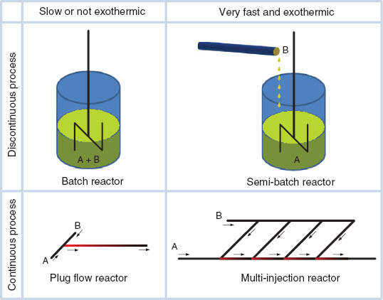
Using multiple injection points for improved thermal control during continuous processing of quasi-instantaneous exothermic reactions.
The aim of the present work is to enable process intensification of rapid and highly exothermic reactions with characteristic reaction times smaller than 1 s, referred to as quasi-instantaneous. To avoid the use of excessively small reactor diameters, a multi-injection reactor is developed. First, the task is addressed on a theoretical level by numerical simulations. Subsequently, the model reaction, i.e., the cyclization of pseudoionone to β-ionone, is studied. To prove the concept, the reactor is made of low temperature co-fired ceramics which enables non-intrusive monitoring of temperature via quantitative infrared thermal mapping. The temperature profiles obtained are correlated to the product distribution demonstrating the process intensification achieved due to enhanced thermal control in the multi-injection MSR.
2 Numerical simulations
To obtain a basic understanding of the key parameters for the design of a multi-injection MSR, its model is built up and solved by numerical simulation using Mathworks Matlab R2009b. The simplified model already described in detail in a previous review [8] is briefly introduced before addressing the benefits of the multiple injection points on the temperature profile. Finally, the critical points for the design of an efficient multi-injection reactor are highlighted.
2.1 Modeling of a multi-injection microreactor
For a multi-injection MSR with N injection points, the mass balance can be derived with a similar approach as for a single-injection MSR [8]. For simplification, the second order derivatives, i.e., axial dispersion of mass and heat are neglected in the following. Hence, a set of ordinary differential equations [see equations (1) and (2)] is obtained with the following main assumptions being done [8, 11]:
No axial conduction of mass and heat
No radial gradients of temperature and concentration within the reaction channel except for the boundary layer to the wall
Constant density and heat capacity for both ingoing educt and the outgoing product streams
Instantaneous mixing of the reactants at each injection point (overall transformation rate governed by the intrinsic reaction kinetics).
As opposed to the first three assumptions, the latter constitutes a simplification compared to a real system: the results obtained with the model represent an ideal situation of instantaneous mixing.
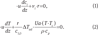
The parameter u is the average flow velocity in axial direction z, ci is the concentration of reactant i and νi is the stoichiometric coefficient. The initial concentration of reactants 1 in the reaction mixture is denoted by c1,0. The temperature is designated by T, the volumetric heat transfer coefficient is Ua, ρ is the density and cp the specific heat capacity. The given equations are solved separately after each injection point as more thoroughly described in a previews review [8].
The modeled multi-injection reactor as depicted in Figure 2 has a total of N=3 injection points with a cross sectional diameter of 500 μm. The injection points are located at a distance of Lj=0.3 m one from another, and the reactor has a total length of Ltot=2 m. The heat evacuation is homogeneous all over the reactor with a volumetric heat transfer coefficient of Ua=8.7×10⁶ W/(m3K).

Simplified scheme of the multi-injection reactor modeled.
The model reaction used for the simulation has to be 1) quasi-instantaneous with a characteristic reaction time below 1 second and 2) highly exothermic. For this reason, the synthesis of the ionic liquid 1-ethyl-3-methylimidazolium ethylsulfate at higher temperature was chosen, whose kinetics is well described in literature [12–14]. The adiabatic temperature rise of the reaction, i.e., the temperature rise obtained in absence of cooling, is ΔTad=166°C. The reaction parameters used for the simulations are summarized in Table 1 together with the default values of the other parameters.
Parameters used for the simulation of a multi-injection reactor [12].
| Parameter | Value |
|---|---|
| Volumetric flow rate, QR [m3/s] | 5×10⁻⁸ |
| Volumetric flow rate, QInj [m3/s] | 3.05×10⁻⁸ |
| Initial conc. of methylimidazole in flow “Inj”, cM,0 [ mol/m3] | 12,540 |
| Initial conc. of diethylsulfate in flow “R”, cD,0 [mol/m3] | 7633 |
| Frequency factor, k0 [m3/mol×s] | 1.28×10⁹ |
| Activation energy, EA [kJ/mol] | 89 |
| Reaction enthalpy, ΔHr [kJ/mol] | -100 |
| Initial and cooling temperature, T0=Tc [°C] | 127 |
| Reactor diameter, d [m] | 0.5×10⁻³ |
| Injection points, N [-] | 3 |
| Volumetric heat transfer coefficient, Ua [W/(m3×K)] | 8.7×10⁶ |
| Volumetric heat capacity, ρ⋅cp | 2.86×10⁶ |
2.2 Simulation results
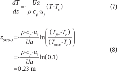
In the present section, the effect of an increasing amount of injection points is demonstrated. As expected, when carrying out the quasi-instantaneous model reaction with one single injection point as shown in Figure 3, a temperature rise close to adiabatic temperature is observed. Due to the short characteristic reaction time of 0.07 s (calculated at the first injection point according to equation 4), the heat is released so quickly that even in a microstructured reactor, the heat removal is too slow.
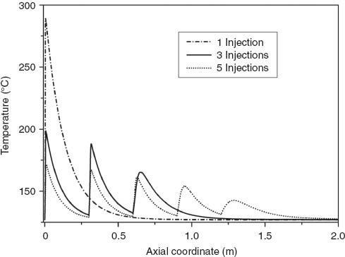
Temperature profile for multi-injection reactors with different amount of injection points.
When working with a total of three injection points, the maximal temperature rise is found to be about half of the one observed with one single injection point. As the heat can be evacuated in the channels in between the distinct injections, a better temperature control is achieved. In addition, the first injection point exhibits a higher temperature than the others, which has two main reasons:
Successive dilution of the reactants from one injection point to another leading to a diminished local adiabatic temperature rise (see [8]). The ratio between adiabatic temperature rise at the j-th injection point in a multi-injection MSR with N injection points and the adiabatic temperature rise in a single injection reactor (N=j=1) is (see [8]):
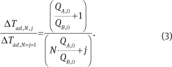
The dilution and the reaction lead to a diminished local characteristic reaction time from one injection point to another. The latter is defined as follows for a second order reaction:
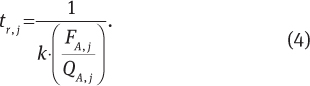
Thereby, the molar flow FA,j decreases due to reaction, and the volumetric flow rate QA,j increases with j:
In the present example with three injection points the characteristic reaction time approximately doubles after each injection.
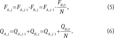
Finally, by increasing the total amount of injection points to five, the maximal temperature can be further reduced to 30% of the adiabatic temperature rise. As already pointed out by Roberge et al. [10], the advantage gained by increasing from one injection point to three injection points are more important compared to the ones obtained by moving from three to five injection points (see Figure 4). Therefore, in general, more than six injection points do not lead to a decisive gain as seen from Figure 4.
Maximal temperature at the first injection point of a multi-injection reactor with equal flow distribution as function of the total amount of injection points.
As opposed to equal dosing at each injection point, by rising the volumetric flow rate of injected fluid from one injection point to the next, the hot spot at the first injection point can be further reduced leading to three equal temperature peaks, as discussed in [8]. However, dosing different volumetric flow rates QB,j for each injection point with one single pump is technically difficult, as complex distribution units have to be designed which strongly depend on the fluidic properties of the reaction mixture. For this reason, in practice equal dosing is preferable.
2.3 Key design criteria for an efficient multi-injection reactor
To benefit from a reduced temperature while carrying out an exothermic reaction with quasi-instantaneous instrinsic kinetics, it is important to avoid insufficient cooling and accumulation of reactants due to poor mixing. While the insufficient cooling leads to an immediate rise in temperature, the accumulation of the reactants represents a safety hazard, as a runaway is likely to occur in downstream equipment.
The accumulation of the reactants can be prevented by using appropriate mixing structures. Many different types of structures are proposed in literature and summarized in a review by Hessel et al. [15]. To chose an efficient structure, one has to define the operation range in terms of Reynolds number (Re=u⋅dh/ν). For a range of 0<Re<100, it is advised to work with mixers based on the multi-lamination principle or with herringbone type structures, whereas for Re>100 one can chose structures whose mixing quality rely on the formation of vortices, such as the tangential or the SZ-mixer [16].
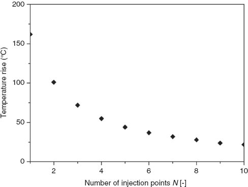
The accumulation of heat can be estimated by correlations of the heat transfer coefficient, which in turn is used to calculate the distance needed for sufficient evacuation of heat in a given reactor geometry [8, 17]. Thereby, one has to bear in mind that the complete evacuation of heat would take an infinitely long reactor, which is why one has to find a reasonable temperature level to be reached before the next injection. For the present case, it was decided that evacuating 90% of the heat produced at the previous injection point is sufficient. Therefore, the minimal evacuation length after the first injection point can be obtained as follows:
where uj is the flow velocity after the j-th injection point, which is equal to 0.31 m/s at j=1. Tmax is the hot spot temperature reached after the injection, and can be estimated for an instantaneous adiabatic temperature rise using equation (3) (Tmax=Tc+ΔTad,N,j). If one wishes to follow strictly the rule of design, the minimal heat removal length Lj increases from one injection point to another (z1=0.23; z2=0.27; z3=0.31), as uj growths with each injection. This concept is theoretically very interesting; however, as it depends on several parameters such as the flow ratio and the reactant properties, it is too complex to implement in practice. Hence, it is sufficient to design the reactor with constant distance between the injection points, setting Lj=const.=z90%,N≈0.3 m. Thereby, at least 90% of the heat is evacuated after each injection point, as the length is chosen according to the worst case, i.e., the last injection point.
In Figure 5, a properly designed multi-injection MSR (>90% of the heat evacuation) with the parameters as given in Table 1 is compared to the same multi-injection reactor with a 10-fold reduced volumetric heat transfer coefficient. Whereas in the first case the required cooling length is respected (Lj=const.=0.3 m>z90%,N), for the second reactor heat removal is insufficient. As a consequence, temperature rises gradually inside the reactor and reaches a temperature level almost 2-fold higher than the properly designed multi-injection MSR. Due to the elevated temperature level of the latter curve, the colder injections provide a sudden drop in temperature, which is immediately followed by a rise due to the reaction.
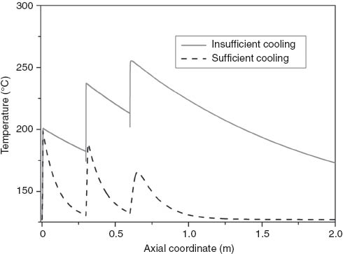
Comparison of a temperature profile with three injections with sufficient cooling and with insufficient cooling between the injection points (L1= L2=L3).
As already mentioned, the concepts of dosing different flow rates at each injection points and of different distances between the injection points have only theoretical value. For this reason, the reactor developed in the experimental part of the present study was designed with equal distances between the injection points and fed with equal flow rates at each injection point.
3 Experimental study
In the following, the model reaction used for the experimental evaluation of the multi-injection principle is described. Subsequently, the multi-injection MSR developed is presented. The quantitative monitoring of temperature profiles has been carried out by infrared thermal mapping and the composition of the outlet flow was determined by gas chromatographic analysis.
3.1 Model reaction
The cyclization of pseudoionone to α-ionone and β-ionone in the presence of sulfuric acid was chosen as model reaction. Due to their olfactory properties, the ionones are used for essential oils and in various other perfumery products [18]. Furthermore, β-ionone is an important compound in the synthesis of vitamin A.
Due to the fast and exothermic nature of this reaction, the cyclization of pseudoionone to α-ionone and β-ionone is the key step in the overall process aiming at high yields of β-ionone from pseudoionone. Thereby, the objective of the first process step is to maximize the combined yield of α-ionone and β-ionone while avoiding the highly exothermic subsequent polymerization, which is triggered by high temperatures and residence times. The mixture of α-ionone and β-ionone formed in the first step is led to the subsequent isomerization step, where α-ionone is almost athermally transformed into the thermodynamically more stable β-ionone. More details on the second process step can be found in a publication by Kashid et al. [18].
Even though the reaction presented in this section is more complex than the synthesis of ionic liquids whose parameters were used for the previously presented numerical simulations, the thermal behavior of both reactions in the multi-injection MSR is almost identical as both are quasi-instantaneous.
While the pure reactants (pseudoionone and sulfuric acid) form two separate phases by using an appropriate solvent (e.g., nitropropane or nitromethane), one can achieve a homogeneous system. In the following, only the studies carried out under homogeneous conditions are reviewed, as they give insight into the intrinsic kinetics. The reaction mechanism was first studied by Semenovskii et al. [19, 20]. They claimed that the rate of reaction is independent of the isomer configuration of pseudoionone. According to their findings, the cyclization leads mainly to the formation of α-ionone (90%) accompanied by a parallel formation of β-ionone (10%). Under certain reaction conditions, α-ionone can be transformed to β-ionone (isomerization). Kashid et al. [18, 21] recently published two studies giving deeper insight into the reaction mechanism of the cyclisation of pseudoionone to β-ionone. At first, they carried out kinetic measurements of the relatively slow and slightly endothermic isomerization reaction in a batch reactor with nitropropane as solvent maintaining the molar ratio of pseudoionone to H2SO4 at 1:4.8. An increase of this ratio led to a diminished yield of the sum of α-ionone and β-ionone. The isomerization follows first order kinetics with respect to α-ionone with an activation energy of EA=65 kJ/mol and a frequency factor of k0=5.4⋅1010 1/s [18]. Subsequently, the very exothermic cyclization of pseudoionone to the final product β-ionone was studied [21]. Due to the rapidity of the reaction, they switched from a batch vessel to a microreactor based system. This allows on the one hand, sampling after short residence time, and on the other hand, evacuation of the heat produced during the exothermic reaction steps. By introducing a non-miscible solvent (perfluorohexane) the authors obtained a narrow residence time distribution. The proposed reaction scheme is depicted in Figure 6. The first step is a quasi-instantaneous protonation of the pseudoionone molecule, followed by the very fast cyclization of the molecule to the intermediate (6). The low activation energy obtained for these reaction steps indicates a mixing influenced regime. Intermediate (6) is in equilibrium with the protonated α-ionone and γ-ionone, and a part of the intermediate is irreversibly transformed to the protonated form of β-ionone. In the last reaction step, quenching by the addition of water, the final products α-ionone, β-ionone and γ-ionone are obtained. Herein, the selectivity to γ-ionone is negligible in comparison to α-ionone and β-ionone due to the chosen conditions. When working at higher temperatures or higher residence times, the kinetically controlled consecutive polymerization of the products causes a loss of selectivity towards the sum of α-ionone and β-ionone [18, 22]. In a semi-batch reactor with a residence time of about 1 h, the critical temperature for the appearance of unwanted polymers was found to be 10°C.
![Figure 6 Reaction scheme of the cyclization of pseudoionone. Adapted from [21].](/document/doi/10.1515/gps-2013-0060/asset/graphic/gps-2013-0060_fig6.jpg)
Reaction scheme of the cyclization of pseudoionone. Adapted from [21].
Kashid et al. [18] also determined the enthalpies of the different reaction steps by combining calorimetric measurements with a theoretical method of group contribution. Herein, the protonation and the cyclization turned out to be extremely exothermic steps. Hence, in combination with high reaction rate this very fast and highly exothermic step (-128 kJ/mol) makes it particularly critical to carry out this reaction, as at elevated temperatures or residence times, the highly exothermic consecutive polymerization of the intermediate (6) is triggered. This reaction not only leads to a loss of yield, but in addition represents a serious safety hazard.
Despite the efforts that have been made in the past decades, the state of the art of industrial production of pseudoionone remains a semi-batch production with dosing times above 60 min at temperatures around 0°C. As a consequence, low space-time yields are achieved and a part of the product is lost due to consecutive polymerization.
For the experiments two inlet solutions were prepared using 1-nitropropane as solvent:
Pseudoionone solution: 1.5–1.25 m in 1-nitropropane
Sulfuric acid solution: 7.5 m sulfuric acid in 1-nitropropane.
The adiabatic temperature rise of the resulting mixture depends on the inlet concentrations and is ΔTad=48–37°C. The physical properties of the pure reactants at 25°C are summarized in Table 2 together with the estimated (assuming linear dependence) properties of the solutions (denoted by *). From the point of view of fluid mechanics, the high viscosity of sulfuric acid and of the target product β-ionone needs to be highlighted. In addition, both inlet solutions have a difference in density of about 400 kg/m3, which renders mixing of both fluids challenging.
Physical properties of the compounds at 25°C used for the homogeneous cyclization of pseudoionone [17]. The properties of α-ionone are assumed to be similar to β-ionone.
| Density (kg/m3) | Heat capacity [J/(kg K)] | Kinematic viscosity (m2/s) | |
|---|---|---|---|
| 1-Nitropropane | 998 | 1972 | 7.90×10⁻⁷ |
| Pseudoionone | 895.1 | 1930 | 6.38×10⁻⁶ |
| β-ionone | 940 | – | 1.15×10⁻⁵ |
| Sulfuric acid | 1840 | 1340 | 1.34×10⁻⁵ |
| Solution Aa | 970 | 1962 | 2.17×10⁻⁶ |
| Solution Ba | 1372 | 1596 | 8.28×10⁻⁶ |
| Product mixturea | 1169 | 1757 | 5.60×10⁻⁶ |
aCalculated properties assuming an initial solution of 1.25 m of pseudoionone and 7.5 m of sulfuric acid.
Hence, for the design of the reactor not only an efficient heat removal has to be integrated, but in addition structures allowing efficient mixing under the above described conditions.
3.2 Multi-injection reactor
Low temperature co-fired ceramics (LTCC) was chosen as a manufacturing technology to build up a ceramic multi-injection MSR to carry out the quasi-instantaneous cyclisation of pseudoionone. It is derived from the thick-film technology area (thicknesses of typically 10 μm) [23], where it has been used for the creation of electronic substrates for high frequency applications. The properties of the LTCC substrates render this material very attractive for the development of microstructured reactors: it is chemically inert even in harsh environments and one can easily create complex 3-D structures through punching, milling and laser cutting processes [24, 25]. The application of this technology to the field of microfluidics is very recent, and the use of LTCC for such a complex development as the present multi-injection reactor has not been reported so far [23, 26–30].
The development of an efficient multi-injection MSR using LTCC was mainly guided by two aspects:
Process intensification and optimization for the combined yield of α-ionone and β-ionone.
Quantitative monitoring of the temperature profile in a multi-injection MSR.
For an optimal heat management required for process intensification of the multi-injection MSR, the criterion elucidated in Section 2 was implemented (evacuation of more than 90% of the heat between the injection points). Thereby, the cross section of the channel was fixed (see below), and the channel length designed to provide sufficient residence time for the cooling of the reaction mixture. A heat transfer coefficient of Ua in the range of 4×10⁶ W/(m3‧K) was determined in preliminary non-reactive experiments, leading to a minimal required residence time of 1.17 s in order to sufficiently evacuate the heat. At the target volumetric flow rate of 3 ml/min, the channel volume of the selected design provides a residence time after the second injection point of τ2=2.5 s, thus, fulfilling the condition.
The second guideline for the development of the multi-injection MSR, i.e., the experimental visualization of the temperature profile using an infrared thermography based method sets some constraints to the reactor design. As the infrared (IR) camera has a limited field of vision (see upcoming section), the total size of the reactor is restrained to an area of 65 mm×32 mm. Furthermore, using IR thermal mapping, it is not possible to monitor temperature inside a reaction channel which is surrounded by liquid coolants [31]. For this reason, the reaction channel can only be cooled from the bottom side, whereas the temperature is monitored from the upper surface. To obtain a quantitative temperature profile with the calibration method described in the upcoming section, the reactor cover thickness should be below 500 μm [11, 31]. Using LTCC technology, a thickness as low as 133 μm could be readily achieved.
The reactor contains essentially two fluidic layers as depicted in Figure 7: the reaction layer containing the educts and products of the reaction and the cooling layer at the bottom, which is passed by isopropanol as heat exchange liquid.
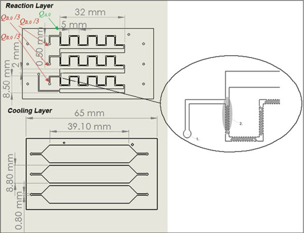
Scheme of the two main layers constituting the multi-injection reactor: the reaction layer (top) contains the herringbone mixing structures, and the cooling layer (bottom) is made up of three large cooling channels covering each one set of a mixing and residence time channel of the reaction layer.
The preheated inlet flow of the sulfuric acid solution is shown in Figure 7 (green arrow), and the first of three injections of pseudoionone solution (brown arrows) is added to the flow before entering the subsequent static mixer. The herringbone mixing structure [32–34] was chosen as static mixer as it was found to be efficient at low Reynolds numbers. In the experiments described in the present study, the Reynolds number were estimated to be in the range of Re≈20. The herringbone mixer was designed with 7 cycles of 10 grooves per half cycle. The groove thickness is 100 μm with a gap of 100 μm between the grooves (2π/q=200 μm). The channel cross section is 560 μm×500 μm (H×W) with the ratio between groove height and free channel height being α=0.30. After the mixing channels, the heat is removed in the larger residence time channels with a rectangular cross section area of 560 μm×2000 μm (H×W), before attaining the next injection.
The cooling layer is formed out of three separately fed large cooling channels with a cross section of 430 μm×8800 μm (H×W) at the widest location. One cooling channel covers one set of static mixer together with the subsequent residence time channel of the reaction layer.
To make the connections between the standard ⅛″ tubing used in the setup and the inlet of the ceramic microstructured reactors, a connection device was manufactured out of alumina. By fixing the reactor into this construction, leak proof connections can be made between the perfluoroalkoxy (PFA) tubes and the reactor openings by using commercially available ethylene tetrafluoroethylene (ETFE) flangeless ferrules. A snapshot of the device fabricated for the multi-injection reactor allowing the eleven connections to be done is given in Figure 8.
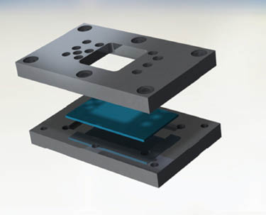
Device constructed to connect the LTCC multi-injection MSR to standard ⅛″ tubing using flangeless ferrules.
3.3 Experimental
In the present section, the experimental setup embedding the multi-injection MSR is presented. Two methods of analysis are used to characterize the reactor: quantitative IR thermography to monitor the axial temperature profiles, and the analysis of the product composition by gas chromatography.
3.3.1 Experimental setup
As previously mentioned, a total of 11 connections were made to connect the multi-injection MSR to its setup. Thereby, the cooling circuit containing isopropanol requires three inlet and three outlet connections. The rotary piston pump continuously feeds the thermal fluid with a minimum flow rate of 80 ml/min leading to a maximal temperature difference of 4°C between inlet and outlet of the multi-injection MSR when operating at 70°C (see Figure 9).
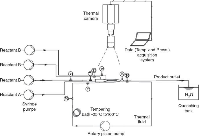
Setup for experimental characterization of the multi-injection MSR.
The reactants are fed using four separate syringe pumps (KDS 100) equipped with Hamilton gastight syringes (50 ml). Using this type of equipment, the pressure at the syringe outlets is limited to 1 bar. The products are quenched at the outlet with a 150 g/l solution of sodium carbonate at 0°C. Temperature at the inlets and outlets is measured by 0.5 mm thick K-type thermocouples and pressure is monitored at the first injection point using pressure gauges with a working range of 0–28 bar and a precision of ±0.15 bar.
The multi-injection MSR with integrated cooling unit was monitored by an IR camera under a constant convective flow of air. Thereby, the aim was to maintain the heat losses via the cover of the reactor to the environment constant by avoiding natural convection, which exhibits a strong dependence on temperature and disturbances from the outside. As the heat evacuation coefficient on the top surface of the channel is much lower than the heat transfer coefficient with the cooling channel, its effect on the overall heat balance is <15%.
3.3.2 Monitoring temperature by infrared thermography
To quantify data from infrared thermographs, a calibration of the setup has been carried out prior to the experiments. The method has already been described elsewhere [31]. For the multi-injection MSR, a slightly different procedure was adopted, which requires a uniform emissivity all over the reactor surface. Due to its flat and homogeneous surface, this assumption can be readily made for the developed multi-injection MSR. Hence, the calibration between liquid temperature inside the reactor channels and the signal measured on the reactor surface by the IR camera can be carried out at one single point, and subsequently applied to measure all over the reactor surface. To further validate the assumptions, the calibration was carried out at the three injection points, confirming that the same calibration curve isobtained at three different locations. Inert liquid (butanol) was fed at temperatures between 25°C and 50°C to one of the three injection points at high flow rates (see point 1 in Figure 7). The temperature was monitored by a thermocouple directly at the inlet (point 1) and compared to the average of the camera signal θ over 10 pixels located on top of the respective injection channel (point 2 in Figure 7). Due to the short distance between thermocouple and calibration pixels (≈4 mm), and because of the high flow rates (≈20 ml/min corresponding to 1.2 m/s), it can be assumed that the temperatures were identical at the two locations within ±0.25°C. The calibration plot in Figure 10 shows that a homogeneous emissivity of ε=1 can be readily applied all over the reactor allowing temperature to be monitored within an overall precision range of ±1°C and a resolution of 160 μm.
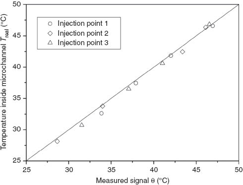
Calibration of the camera signal to the temperature measured by thermocouples at three injection points.
3.3.3 Product analysis by gas chromatography
After separating the organic phase from the aqueous phase, analysis of the product distribution is carried out in a Perkin-Elmer Auto System XL chromatograph equipped with a programmed split/splitless injector and a flame ionization detector employing a Stabilwax (Cross-bond Carbowax-PEG, Restek, USA) capillary column (i.d.=0.32 mm, length=30 m, film thickness=0.25 μm). The calibration of the chromatograph was carried out with 90% pseudoionone supplied by Aldrich, 96% β-ionone supplied by Acros, and 90% solution of α-ionone supplied by Aldrich. Thereby, the calibration curve was found to be quasi-identical for the three molecules. As internal standard, 99.5% butanol by Alfa Aesar is added to the sample before the injection into the chromatograph. To obtain a representative product composition, the analysis of each sample is performed three times.
4 Characterization of the reactor performance
The results presented in the following are divided according to the methods: first the results from IR thermal mapping are presented followed by the product distribution obtained at the outlet of the multi-injection MSR.
4.1 Temperature profiles in the multi-injection microreactor
The temperature profiles were determined while keeping the coolant temperature constant Tc=48°C with reactant concentrations of cH2SO4=7.5 m and cPI=1.5 m in both inlet solutions, respectively. The total flow rate was 3 ml/min with 0.5 ml/min of pseudoionone fed at each of the three injection points. Considering the adiabatic temperature rise of ΔTad=48°C, the maximal temperature to be expected is Tad=96°C. At first, in Figure 11, the temperature profiles obtained with one injection point (1.5 ml/min of pseudoionone solution via the first injection point) are compared to the temperature profiles measured with three injection points. The initial temperature is slightly lower (43°C) than the coolant temperature (48°C) due to the short preheating length. Within the static mixer, temperature rises up to about 60°C due to the quasi-instantaneous protonation and the fast consecutive cyclization. The maximum temperature of 62°C is reached at the exit of the herringbone mixer, where the cooling performance is lower than within the herringbone mixer. After reaching the hot spot temperature, temperature continuously diminishes as no more exothermic reaction is occurring. When working with three injection points, a similar behavior is observed after the first injection point: temperature continuously increases inside the herringbone mixer, and at the exit, a temperature maximum of 54°C is reached. The same profile is observed for the second injection point, whereas for the third injection point the maximal temperature reached is even lower.
![Figure 11 Temperature profile during the cyclization of pseudoionone in the multi-injection MSR with one injection point (left) and with three injection points (right). Initial concentration of the two inlet solutions: cH2SO4 =7.5 m and cPI =1.5 m; total flow rate: 3 ml/min (0.18 m/s); ΔTad=48°C; Tc=48°C [11].](/document/doi/10.1515/gps-2013-0060/asset/graphic/gps-2013-0060_fig11.jpg)
Temperature profile during the cyclization of pseudoionone in the multi-injection MSR with one injection point (left) and with three injection points (right). Initial concentration of the two inlet solutions: cH2SO4 =7.5 m and cPI =1.5 m; total flow rate: 3 ml/min (0.18 m/s); ΔTad=48°C; Tc=48°C [11].
As expected, the maximum temperature reached with one injection point is about 8°C higher than the hot spot temperature monitored while working with three injections. This corresponds to a temperature rise of 29% of the adiabatic temperature rise in the former case, and of about 12% in the latter case (using 48°C as reference temperature). Compared to the numerical simulations shown in Section 2, where the according values were 99% and 44% respectively, the hot spot temperature obtained in the experiments are much lower. This difference is because of the fact that while the simulation assumes quasi-instantaneous transformation of the reactants, this is not the case in the experiments. The gradual mixing of the reactants along the herringbone mixer leads to a reduced overall transformation rate, which facilitates temperature control.
As a consequence, the hot spot temperature is sensitive to the volumetric flow rate: the higher the flow rate, the faster is the overall transformation rate (the mixing), and in turn, the higher the maximal temperature in the microstructured reactor (as shown in Figure 12). Thereby, the hot spot temperature obtained in the numerical simulations always represents the worst case. Nevertheless, as already demonstrated in the simulations, a more than two-fold reduced temperature rise is achieved by increasing the amount of injection points from 1 to 3.
4.2 Product composition
As described in Section 3 of the present study, the objective of the multi-injection MSR is to maximize the combined yield of α-ionone and β-ionone, while preventing the temperature triggered polymerization of the molecules.
The results presented as follows were obtained at a total flow rate of 3 ml/min corresponding to a flow velocity of 0.18 m/s in a channel with the dimensions 560 μm×500 μm (H×W). The residence time of the molecules entering via the first injection point corresponds to 4.1 s, whereas the molecules entering the two subsequent injection points have residence times of 2.5 s and 1.1 s, respectively.
Besides the concentrations of pseudoionone, α-ionone and β-ionone, the yield of the 10-hydroxy derivates (isomers), denoted as intermediates (5) in Figure 6, was monitored. They were used as indicator for an incomplete reaction, as their appearance is coupled with the appearance of other peaks of intermediate molecules. The product compositions obtained as function of coolant temperature are given in Figure 13.
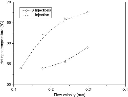
Maximum temperature while carrying out cyclization of pseudoionone in the multi-injection reactor with one injection point and with three injection points.
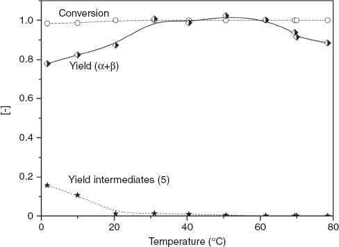
Yield and conversion at the outlet of the multi-injection reactor during cyclization of pseudoionone as function of coolant temperature. Thereby α and β denote α-ionone and β-ionone, and intermediates (5) are two isomers of 6,10-dimethylundeca-3,5-dione-10-hydroxy-2-one. Total flow rate: 3 ml/min (0.18 m/s), initial concentrations: cPI = 1.25 m; cH2SO4 =7.5 m.
The concentration of pseudoionone found in the outlet stream is very low, independent of the temperature. Hence, a conversion of the reactants close to 1 is obtained all over the temperature range from 0°C to 80°C. Despite the high conversion, in the range of 0°C–30°C, yields of α-ionone and βionone are considerably lower than 1. At the same time, the concentration of intermediates found in this temperature range is relatively high, indicating incomplete reaction, which can be brought back to an insufficient overall transformation rate at such low temperatures. It has to be stressed out at this point, that only the protonation of pseudoionone is quasi-instantaneous, while the subsequent reaction steps towards α-ionone and β-ionone can only be considered as slower. When working between 3°C and 60°C, the intermediates in the outlet stream disappear and a combined yield of α-ionone and β-ionone above 98% is observed. Hence, operating the reactor in this temperature range at 3 ml/min leads to an optimal result. If temperature is further increased to above 60°C, the yield of α-ionone and β-ionone drops. As the concentrations of intermediates remains negligible, this drop in yield is ascribed to the unwanted consecutive polymerization. Whereas the latter effect of yield loss is already observed at temperatures above 10°C in a semi-batch reactor [18], the multi-injection MSR allows operating at much higher temperatures as short residence times and good temperature control prevent the appearance of consecutive polymerization up to 60°C. Furthermore, the proportion of β-ionone continuously increases when moving towards higher temperatures.
4.3 Process intensification
The process intensification achieved with the multi-injection MSR is compared to a semi-batch reactor with a dosing time of 60 min. It is assumed that within τbatch=60 min, a yield of β-ionone of 0.98 is obtained in the semi-batch reactor, which is optimistic compared to the real case. To obtain pure β-ionone, a residence time loop has to be connected in series to the multi-injection reactor, where the isomerization from the remaining α-ionone to β-ionone is carried out. The maximal residence time in the multi-injection MSR is τ1=4.1 s. Assuming a working temperature of 40°C, converting 99% of the α-ionone left after the first step can be easily estimated by supposing an isothermal plug flow reactor [35]. The first order reaction kinetics of the isomerization have been recently published by Kashid et al. [18]:
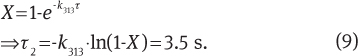
The intensification factor is then obtained by relating the residence time of both processes:
By moving from a conventional semi-batch process to the multi-injection MSR based process, a gain in space-time yield of a factor 500 can be achieved.
5 Conclusion
In the present study, multi-injection MSR concept for process intensification for quasi-instantaneous reactions has been studied theoretically and proved experimentally. The numerical simulation showed that the temperature rise in the multi-injection MSR can be well controlled by increasing the amount of injection points. However, when exceeding six injection points, the advantages of every additional injection points becomes marginal. For the practical reasons, it is crucial to avoid the accumulation of the reactants and heat. The former can be prevented by choosing an appropriate mixing structure, while the latter can be achieved by considering sufficient residence time for the heat exchange between the injection points (estimated from correlations).
For the monitoring of the temperature profile within the multi-injection MSR channels, a simple method of quantitative infrared thermography was applied with the calibration prior to the experiments. The temperature was determined with a precision of ±1°C and a resolution of 160 μm.
The experimental temperature profiles showed even better temperature control than predicted by the numerical simulation. This could be attributed to a gradual mixing of the reactants within the herringbone mixing structure as opposed to the instantaneous mixing supposed in the numerical simulation. Hence, the overall transformation rate of the quasi-instantaneous reactions is reduced, leading to a flatter temperature profile. Furthermore, it was shown that injecting pseudoionone via three injection point leads to a two-fold reduction in temperature rise as compared to a single injection MSR. Thus, operating with the presented multi-injection MSR leads to an eight-fold reduction of hot spot temperature as compared to adiabatic temperature rise in a conventional batch reactor.
In a temperature range of 30°C–60°C, a yield >98% towards α-ionone and β-ionone is achieved. The consecutive polymerization which occurs already at temperatures >10°C in semi-batch reactors can efficiently be suppressed up to a temperature of 60°C. Thus, using the multi-injection MSR, an improvement of space-time yield of a factor 500 is achieved compared to the conventional semi-batch reactor process.
Furthermore, the multi-injection MSR developed in the present work is not limited to the presented model reaction but has a general nature. It can be used for any quasi-instantaneous reaction as for this type of reaction the overall transformation rate is controlled by the mixing of the reactants.
About the authors

Julien Haber studied Process Engineering at the University of Bayreuth, Germany. In 2010 he joined the Group of Catalytic Reaction Engineering obtaining his PhD degree in 2013. His research work focused on continuous processing, particularly on the intensification of industrial chemical processes using microreactors. He now works as Senior Scientist at Novartis Pharma AG in Basel, Switzerland.

Bo Jiang received his Master of Materials Science from Alfred University, New York, USA, in 2009 for his work on high temperature X-ray diffraction characterization of chrome poisoning in cathode materials of solid oxide fuel cells. After working briefly at Hybrid Silica Technology Incorporated in Boston, MA, USA, where he was in charge of developing silica nanoparticles production, he moved to Lausanne, Switzerland in 2010. At Ecole Polytechnique Fédérale de Lausanne (EPFL) he is carrying out his doctoral research in area of thick film technology for developing microsystems under the supervision of Professor Paul Muralt and Dr. Thomas Maeder.

Thomas Maeder graduated in Materials Science and gained his PhD in the field of piezoelectric thin films at the Ecole Polytechnique Fédérale de Lausanne (EPFL), Lausanne, Switzerland. This was followed by postdoctoral studies in single-crystal conductive oxides at IBM Zurich Research Laboratory, Switzerland. He now heads the thick-film technology group at the EPFL. His main fields of research are thick-film and low-temperature cofired ceramic (LTCC) technology for advanced sensor and packaging applications, which take advantage of their unique properties: hermeticity, high-temperature resistance, integration of many functions, and ease of 3-D structuration.

Albert Renken studied chemistry at the University of Hannover, where he earned his Master’s (Diploma) degree in 1966 and his PhD in 1968. In 1973 he obtained the Habilitation in Chemical Engineering. From 1970 to 1977 he was a lecturer in Chemical Reaction Engineering at the University of Hannover, Germany, and worked from 1973 to 1977 at Hoechst Limited, Frankfurt am Main, Germany, as a group leader in the Department of Chemical Engineering. In 1977 he became a Professor in Chemical Reaction Engineering at the Swiss Federal Institute of Technology in Lausanne, Switzerland, and retired in 2006. His scientific interests are: Heterogeneous catalytic engineering, unsteady-state operation of chemical reactors, structured catalytic reactors, and micro-structured reactors. Albert Renken was a member of the research council of the Swiss National Science Foundation (Division of Mathematics, Natural Science and Engineering) from 1992 until 2000, a member of the Swiss Innovation Promotion Agency (CTI) from 1999 to 2006. He is a Swiss delegate of the working party on Chemical Reaction Engineering (Chairman 1996–2003) of the European Federation of Chemical Engineering, and a member of the European Network of Excellence: “Integrated Design of Catalytic Nanomaterials for a Sustainable Production (IDECAT)”. He organized the 7th International Conference on Microreaction Technology (IMRET 7) in Lausanne in 2003 and the 19th International Symposium on Chemical Reaction Engineering (ISCRE 19) in Berlin/Potsdam, Germany in 2006. In 2007 he was awarded the DECHEMA-Medal for his engagement and pioneering contributions to Chemical Reaction Engineering and Microreaction Technology. He is the author/co-author of more than 400 scientific publications, 16 patents and two textbooks in chemical reaction engineering.

Lioubov Kiwi-Minsker is a Professor at the Swiss Federal Institute of Technology in Lausanne (EPFL) where she has been working since 1994. She is currently a head of the group of Catalytic Reaction Engineering at EPFL. Her research interests are in the fields of novel catalytic materials and microreactor technology for process intensification. She is a co-author of more than 200 peer reviewed publications, six book contributions and seven patents (H-index=33).
The authors acknowledge the financial support from the 7th European Framework Program COPIRIDE Project (Grant agreement number: CP-IP 228853-2).
References
[1] Hessel V. Chem. Eng. Technol. 2009, 32, 1655–1681.Suche in Google Scholar
[2] Stankiewicz AI, Moulijn JA. Ind. Eng. Chem. Res. 2002, 41, 1920–1924.Suche in Google Scholar
[3] Stankiewicz AI, Moulijn JA. Chem. Eng. Prog. 2000, 96, 8–8.Suche in Google Scholar
[4] Roberge DM, Gottsponer M, Eyholzer M, Kockmann N. Industrial Design, Scale-up, and Use of Microreactors. Teknoscienze: Milan, Italy, 2009.Suche in Google Scholar
[5] Jähnisch K, Hessel V, Löwe H, Baerns M. Angew. Chem. Int. Ed. 2004, 43, 406–446.Suche in Google Scholar
[6] Kockmann N, Gottsponer M, Zimmermann B, Roberge DM. Chem. Eur. J. 2008, 14, 7470–7477.Suche in Google Scholar
[7] Kiwi-Minsker L, Renken A. Catalysis Today. 2005, 110, 2–14.Suche in Google Scholar
[8] Haber J, Kashid MN, Renken A, Kiwi-Minsker L. Ind. Eng. Chem. Res. 2012, 51, 1474–1489.Suche in Google Scholar
[9] Fukuda T, Sawada M, Maki T, Mae K. Chem. Eng. Technol. 2013, 36, 968–974.Suche in Google Scholar
[10] Roberge DM, Bieler N, Mathier M, Eyholzer M, Zimmermann B, Barthe P, Guermeur C, Lobet O, Moreno M, Woehl P. Chem. Eng. Technol. 2008, 31, 1155–1161.Suche in Google Scholar
[11] Haber J. Heat Management for Process Intensification of Fast Exothermic Reactions in Microstructured Reactors, EPF Lausanne: Lausanne, 2013.Suche in Google Scholar
[12] Große Böwing A, Jess A. Chem. Eng. Sci. 2007, 62, 1760–1769.Suche in Google Scholar
[13] Renken A, Hessel V, Löb P, Miszczuk R, Uerdingen M, Kiwi-Minsker L. Chem. Eng. Process. 2007, 46, 840–845.Suche in Google Scholar
[14] Willmes S, Jess A. Chem. Eng. J. 2013, 222, 198–208.Suche in Google Scholar
[15] Hessel V, Lowe H, Schonfeld F. Chem. Eng. Sci. 2005, 60, 2479–2501.Suche in Google Scholar
[16] Holvey CP, Roberge DM, Gottsponer M, Kockmann N, Macchi A. Chem. Eng. Proc. Intensif. 2011, 50, 1069–1075.Suche in Google Scholar
[17] Verein Deutscher Ingenieure, VDI-Wäarmeatlas, VDI-Verlag GmbH, Düsseldorf, Germany, 2002.Suche in Google Scholar
[18] Kashid MN, Yuranov I, Raspail P, Prechtl P, Membrez J, Renken A, Kiwi-Minsker L. Ind. Eng. Chem. Res. 2011, 50, 7920–7926.Suche in Google Scholar
[19] Semenovskii AV, Smith VA, Kucherov VF. Dokl. Akad. Nauk. SSSR+. 1960, 132, 1107 –1107.Suche in Google Scholar
[20] Smith VA, Semenovskii AV, Medvedeva VM, Kucherov VF. Dokl. Akad. Nauk. SSSR+. 1959, 124.Suche in Google Scholar
[21] Kashid M, Detraz O, Moya MS, Yuranov I, Prechtl P, Membrez J, Renken A, Kiwi-Minsker L. Chem. Eng. J. 2013, 214, 149–156.Suche in Google Scholar
[22] Royals EE. Ind. Eng. Chem. 1946, 38, 546–548.Suche in Google Scholar
[23] Birol H, Fabrication of Low Temperature Co-fired Ceramic (LTCC)-based Sensor and Micro-fluidic Structures, EPFL: Lausanne, Switzerland, 2007.Suche in Google Scholar
[24] Jiang B, Maeder T, Muralt P. PowerMEMS 2010, 10th International Workshop on Micro and Nanotechnology for Power Generation and Energy Conversion Applications, Leuven, Belgium, 2010.Suche in Google Scholar
[25] Valant M, Suvorov D. J. Am. Ceram. Soc. 2000, 83, 2721–2729.Suche in Google Scholar
[26] Golonka LJ. Bull. Pol. Acad. Sci.2006, 54, 221–231.Suche in Google Scholar
[27] Golonka LJ, Roguszczak H, Zawada T, Radojewski J, Grabowska I, Chudy M, Dybko A, Brzozka Z, Stadnik D. Sens. Actuators, B, 2005, 111–112, 396–402.10.1016/j.snb.2005.03.065Suche in Google Scholar
[28] Golonka LJ, Zawada T, Radojewski J, Roguszczak H, Stefanow M. Int. J. Appl. Ceram. Technol. 2006, 3, 150–156.Suche in Google Scholar
[29] Groß GA, Thelemann T, Schneider S, Boskovic D, Köhler JM. Chem. Eng. Sci. 2008, 63, 2773–2784.Suche in Google Scholar
[30] Smith B, Pleskach M, Gamlen C, in, 2003, pp. 217–222.Suche in Google Scholar
[31] Haber J, Kashid MN, Borhani N, Thome J, Krtschil U, Renken A, Kiwi-Minsker L. Chem. Eng. J. 2013, 214, 97–105.Suche in Google Scholar
[32] Cantu-Perez A, Barrass S, Gavriilidis A. Chem. Eng. J. 2010, 160, 834–844.Suche in Google Scholar
[33] Williams MS, Longmuir KJ, Yager P. Lab Chip. 2008, 8, 1121–1129.Suche in Google Scholar
[34] Stroock AD, Dertinger SKW, Ajdari A, Mezić I, Stone HA, Whitesides GM. Science. 2002, 295, 647–651.Suche in Google Scholar
[35] Levenspiel O. 3rd ed., Chemical Reaction Engineering, 1999.Suche in Google Scholar
©2013 by Walter de Gruyter Berlin Boston
This article is distributed under the terms of the Creative Commons Attribution Non-Commercial License, which permits unrestricted non-commercial use, distribution, and reproduction in any medium, provided the original work is properly cited.
Artikel in diesem Heft
- Masthead
- Masthead
- Graphical abstracts
- In this issue
- Editorial
- “Teamed Science” – the Future, and is 1+1=3?
- CoPIRIDE
- EU FP7 Project CoPIRIDE – towards new production and factory concepts for a sustainable and competitive European chemical industry
- Investigations on the anionic polymerization of butadiene in capillaries by kinetic measurements and reactor simulation
- Supercritical fluid technology in biodiesel production: pilot plant design and operation
- Supercritical fluid technology in biodiesel production
- Selective epoxidation of soybean oil with performic acid catalyzed by acidic ionic exchange resins
- Multi-injection microstructured reactor for intensification of fast exothermic reactions: proof of concept
- Novel manufacturing techniques for microstructured reactors in industrial dimensions
- Bridging sustainability and intensified flow processing within process design for sustainable future factories
- Process intensification in gas-to-liquid reactions: plasma promoted Fischer-Tropsch synthesis for hydrocarbons at low temperatures and ambient pressure
- Original articles
- Atom- and step-economic synthesis of biaryl-substituted furocoumarins, furoquinolones and furopyrimidines by multicomponent reactions and one-pot synthesis
- Development of a continuous emulsification process for a highly viscous dispersed phase using microstructured devices
- Conference announcements
- Ecochem: Free Conference & Exhibition on Sustainable Chemistry & Engineering (MCH Congress Center, Basel, Switzerland, November 19–21, 2013)
- 3rd Industrial Green Chemistry World: Convention & Ecosystem (IGCW-2013; Mumbai, India, December 6–8, 2013)
- 52nd Eastern Analytical Symposium and Exposition (EAS2013): Analytical in Motion: Knowledge, Network, and Career (Somerset, NJ, USA, November 18–20, 2013)
- 2nd International Flow Chemistry Asia Conference and Tradeshow, held in association with the Flow Chemistry Society (Singapore, November 14–15, 2013)
- 15th Brazilian Meeting on Organic Synthesis (15th BMOS): Applied Organic Synthesis in Action: Strategies and Process Development (Campos do Jordão, Brazil, November 10–13, 2013)
- 1st International Symposium on Nanoparticles/Nanomaterials and Applications (ISN2A-2014; Costa de Caparica, Portugal, January 20–22, 2014) and 1st International Conference on Ultrasonic-based Applications: from Analysis to Synthesis. (ULTRASONICS2014; Costa de Caparica, Portugal, September 15–17, 2014)
- Sustainable Oil and Gas 2013 (Edinburgh, Scotland, November 25–26, 2013)
- Conferences 2013–2017
- Book reviews
- Biomimetics: a molecular perspective
- Right first time in fine-chemical process scale-up
- Chemical photocatalysis
- Industrial separation processes: fundamentals