Characterization of Fabric-to-Fabric Friction: Application to Medical Compression Bandages
-
Fanette Chassagne
 ,
Emilie Benoist
,
Emilie Benoist

Abstract
Fabric-to-fabric friction is involved in the action mechanism of medical compression devices such as compression bandages or lumbar belts. To better understand the action of such devices, it is essential to characterize, in their use conditions (mainly pressure and stretch), the frictional properties of the fabrics they are composed of. A characterization method of fabric-to-fabric friction was developed. This method was based on the customization of the fourth instrument of the Kawabata Evaluation System, initially designed for fabric roughness and friction characterization. A friction contactor was developed so that the stretch of the fabric and the applied load can vary to replicate the use conditions. This methodology was implemented to measure the friction coefficient of several medical compression bandages. In the ranges of pressure and bandage stretch investigated in the study, bandage-to-bandage friction coefficient showed very little variation. This simple and reliable method, which was tested for commercially available medical compression bandages, could be used for other medical compression fabrics.
1 Introduction
Fabric-to-fabric friction is involved as one of the underlying mechanisms in many medical devices. In these applications, friction is sometimes only a negligible phenomenon, whereas in others, it is a salient feature directly impacting the function of the device. In such cases, an accurate understanding and characterization of friction is of highest importance and deserves specific studies. One of these applications is medical compression bandage therapy in which a textile bandage is wrapped with two or three overlaps around the lower limb within the aim to apply controlled pressure onto the skin. Pressure itself is the active principle of the therapy; however, when wrapped around a leg for instance, static friction prevents bandage slippage [1] while dynamic friction involved during the wrapping process is likely to influence the final pressure distribution on the limb, hence being a key feature to ensure the desired function.
Friction between two materials was, and is still, very widely studied in conventional material science, like metallic material science. Literature and experimental equipment dedicated to textile material friction properties are slightly less abundant [2].
The simplest description of frictional behavior is Amonton’s law (which includes Coulomb’s), which states that:
with F and N, respectively, the tangential and normal contact forces. The friction coefficient, μ, is generally different in static situation, prior to movement initiation and in dynamic situation when sliding between both surfaces occurs. Experimental studies have shown that for viscoelastic material-like fabrics, the relationship between the normal and tangential forces was not linear. Even though other more refined, but more complex, friction laws exist, this simple law is very widely used in modeling and especially numerical simulation.
Interest in studying the geometry of fabric surfaces by developing experimental characterization of friction coefficient can be dated to 1955, when Butler et al. [3] described their “cloth profile recorder”. Development of numerous methods most often involving a linear planar motion of a body on another one are named “contact measurement method” [2]. For the measurement of static coefficient, the inclined plane is the simplest method. To obtain the dynamic coefficient, sled-type techniques, based on a planar body surface and a device to control the displacement of the other body surface are the most common. Note that alternative techniques exist like Capstan’s method, in which fabric is wrapped and rolled around a cylindrical surface, or the twist method in which two fabrics are twisted together [2]. The selection of the appropriate characterization technique and associated equipment should ideally depend not only on the nature of the studied contact (point, line, surface), the environment (temperature, humidity, etc.) [4], the type of fabric, but also the method used to control the normal force and the displacement, and to measure the friction force [2].
Characterizing the touch of fabrics or fabric-to-fabric friction was another motivation that led to several previous studies. A work by Ramkumar et al. [5] aimed to develop a polymeric human finger sensor used in a sled-type friction measurement device. Similarly, though more simple, one of the modules of the system developed by Kawabata [6] was designed to characterize friction related to the hand of fabrics and was used in previous studies [7]. This module relies upon a point-plane friction principle, in which a metallic contactor devised to reproduce a fingertip is rubbed over a plane fabric while applying a constant predefined pressure. Fabric-to-fabric friction usually yields different, higher, friction coefficients. Moorthy et al. [8] used a plane-plane system to determine static and dynamic friction coefficients between fabrics made of non-conventional fibers and focused on the influence of the fibers, their blend and proportion. Because fabric-to-fabric friction coefficient also depends on the geometrical structure of the fabric (e.g., yarn structure, crimp height, etc.), the studies by Ajayi [9, 10] aimed at detailing such relationships. An in-house plane-plane friction bench test was used to shed light on precise mechanisms underlying fabric friction properties. In particular, the evolution of hairiness and its influence on friction coefficients were studied, showing that hairiness decreased with increased contact pressure and with increased number of movements, hence reducing the friction coefficient. Relationships between fabric structure and frictional properties could also be addressed demonstrating, for instance, that yarn density directly influences the friction coefficient of a fabric due to protruding yarns effects.
To sum up this short overview of the literature, each method was specifically designed either for measurements related to an application or for characterizations of friction mechanisms. However, none of them addressed the problem of fabric-to-fabric friction characterization in use conditions, like use under tension (and thus stretched), which is typical of many medical applications, for instance. To address this lack, the objective of the present study was to develop an experimental technique based on the existing and recognized equipment of Kawabata. The system presented in this article includes adjustment of both fabric stretch and contact pressure to evaluate their respective influence on the measured fabric-to-fabric dynamic friction coefficient. An application is proposed through an experimental campaign carried out on medical compression bandages.
2 Methods
Tests were conducted under standard conditions: 20°C ± 2°C and 65% ± 2% R.H. according to ISO standard 139:2005 [11].
2.1 Compression bandages
Compression bandages are textile medical devices designed for the treatment of some venous or lymphatic pathologies. The treatment consists in wrapping a stretched bandage around the limb, hence applying an interface pressure on the limb thanks to the tension in the fabric. The interface pressure, which is the active principle of the therapeutic treatment, depends on several parameters such as the bandage tension, the leg geometry, the number of layers, and other parameters such as bandage-to-bandage contact interactions [12]. Moreover, bandage-to-bandage frictional properties prevent bandage slippage and are thought to have an impact on interface pressure variation between rest state and exercise.
First, the frictional properties of several medical compression bandages were investigated under conditions close to their use conditions. The selected bandages were the Biflex® 16, the Biflex® 17, the Flexideal®, the Biflexideal® and the Cotton bandage, all manufactured by Thuasne (Levallois Perret, France), but also the bandage Rosidal® K, manufactured by L&R (Rengsdorf, Germany). Their characteristics are given in Table 1. These bandages consisted in a representative sample of commercially available bandages, with different textile structures. It is expected that the characterization of their frictional properties will provide a range variation of friction coefficient.
Characteristics of the bandages
| Biflex® 16 | Biflex® 17 | Flexideal® | Biflexideal® | Cotton Bandage | Rosidal® K | ||
|---|---|---|---|---|---|---|---|
| Type of weave | Leno weave | Leno weave | Plain weave | Plain weave | tubular knitted Jersey | Plain weave | |
| Composition* | 51/40/5/4 Vi/PES/Pa/El | 54/31/3/12 Vi/PES/Pa/El | 47/35/17/1 Pa/Vi/PES/El | 65/33/2 Co/Vi/El | 100 Co | 100 Co | |
| Area density [g/m2] | 389 | 511 | 223 | 248 | 200 | 350 | |
| Number of yarn/cm, warp | 22 | 22 | 20 | 16 | 14 courses/cm | 17 | |
| Number of yarn/cm, weft | 15 | 20 | 9 | 11 | 14 | ||
| Force-to-stretch a 10 cm bandage width at stretch = 1.3 [N] | 7 | 13 | 3.2 | 1.3 | 19 | 2.2 (27 at stretch = 1.72) | |
| Yarn count [Tex] | Elastic warp yarn | 135 | 125 | 8 | 29 | N/A | N/A |
| Nonelastic warp yarn 1 | 26 | 26 | 16 | N/A | 20 | 40 | |
| Nonelastic warp yarn 2 | 16 | 16 | N/A | N/A | N/A | N/A | |
| Weft yarn | 40 | 40 | 33 | 71 | N/A | 72 | |
- *
Composition: Vi = Viscose, PES = Polyester, Pa = Polyamide, El = Elastane, Co = Cotton
In a second phase, the impact of applied pressure and stretch on frictional properties was evaluated for only two bandages: the Biflex® 16 (B16) and the Biflex® 17 (B17) (Figure 1), which were selected because they have a very similar fabric structure but different mechanical properties (stiffness). They mainly differ in their core elastic yarn, whose force at stretch = 1.3 is higher for the B17 (12.3 cN) than for the B16 (5.7 cN). According to the manufacturer’s recommendations, these bandages should be applied on the lower limb with a 1.3 stretch (stretch = L/L0, with L the post-application length of the bandage and L0 its initial length).

Cross-sectional images of bandages B16 (top) and B17 (bottom) obtained in X-ray micro-tomography (Phoenix Nanotom® S) in the weft (left) and warp (right) planes and at three different stretch levels (1.0, 1.2, and 1.4).
2.2 Kawabata Evaluation System (KES)
The Kawabata Evaluation System (KES) was designed for the standard evaluation of fabric hand [6]. It is composed of four instruments [13]. Six characterization tests can be performed thanks to these different devices: tensile and shear tests, pure bending test, compression test, and friction and roughness measurements. Only the last of these four systems was of interest in the present study: the KES-FB4. In this study, it was partly redesigned to characterize fabric-to-fabric dynamic friction coefficient.
2.2.1 Characterization of fabric frictional properties
2.2.1.1 KES-FB 4
The purpose of this device is to mimic a human finger touching the fabric. For this, a 5mm long friction contactor, composed of ten 0.5 mm diameter steel piano strings (mimicking the finger ridges), is in contact with the fabric (Figure 2). This contactor is linked to the frictional force sensor and a normal load (49.8 cN) is applied on the contactor (equivalent to a 50 g weight). Then, the fabric underwent a 3 cm translation motion, with return, under the friction contactor, at a constant speed equal to 1 mm/s. The instantaneous dynamic friction coefficient is computed thanks to the following equation (Amonton’s law):
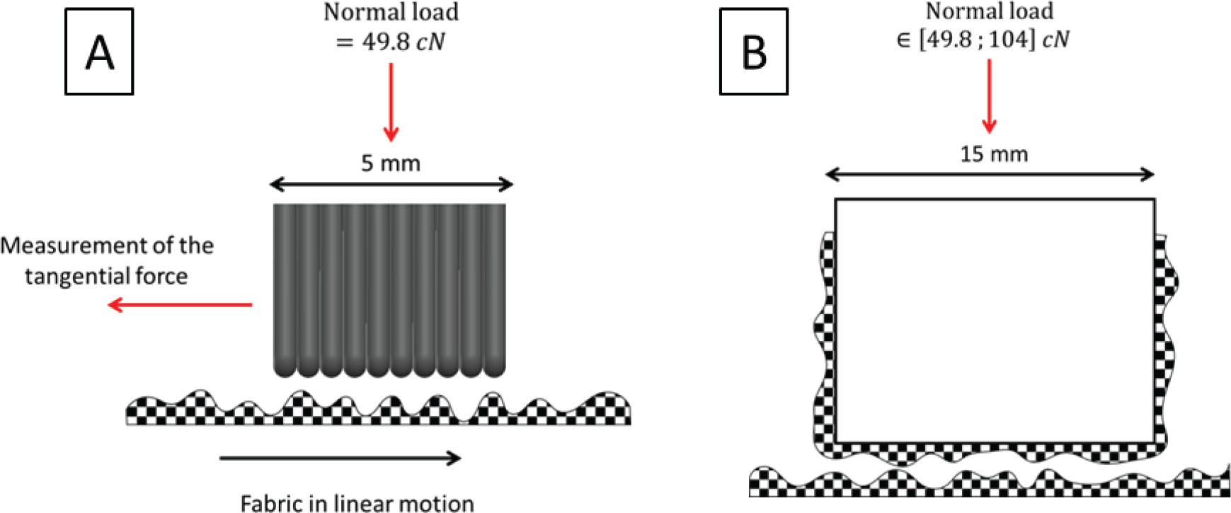
Illustration of the two friction contactors: A, the initial one from the KES and B, the one designed for fabric to fabric friction characterization.
It is then averaged over the fabric displacement, the first and last half centimeter of the translation motion (i.e., the acceleration and deceleration phases) not being taken into account for this computation (Figure 7). Consequently, the friction coefficient obtained and provided by the device is the dynamic friction coefficient.
The KES is only suitable for fabrics to metal friction characterization. Moreover, the contact area of the sensor could be quite small with respect to the fabric pattern. However, it is a reliable and simple measurement tool [14], hence the idea to use this module but to design a new friction contactor.
2.2.1.2 Fabric-to-fabric friction contactor
Within the aim of proposing a simple characterization method of fabric-to-fabric friction, a new friction contactor was designed (Figure 2B and Figure 3B). It was composed of a metal cube on which the fabric was fully taped with the required stretch (to prevent any slippage between the fabric and the friction contactor on which it was set on). Different weights could be set on the contactor to adapt the normal load within the experimentally observed range of pressure [12] (Table 2).

(A) Stretching frame: the fabric is set in the jaws with no stretch, then the translation of the jaw stretches in a homogeneous way the fabric. Once stretched, the fabric is fixed in the holding frame and removed from the jaws. (B) Holding frame and friction contactor used for the measurement of fabric to fabric friction coefficient.
Different normal loads applied for the characterization of friction coefficient
| Applied weight (g) | Normal force (cN) | Pressure (kPa) | Pressure (mm Hg) |
|---|---|---|---|
| 50.8 | 49.8 | 2.22 | 16.6 |
| 65.4 | 64.2 | 2.85 | 21.4 |
| 80.5 | 79.0 | 3.51 | 26.3 |
| 95.2 | 93.4 | 4.15 | 31.1 |
| 106.1 | 104.1 | 4.63 | 34.7 |
The contactor was linked to the KES-FB4 frictional force transducer. However, the automatic data postprocessing was based on the assumption that the normal load was 48.9 cN (corresponding to a 50 g weight). Therefore, a correction of the data given by the KES-FB4 was required:
2.2.1.3 Tensioning and holding frames
The pressure applied on the limb by compression bandages is the direct consequence of fabric stretch, and it is the active principle of the therapeutic treatment. Thus, it was primordial to perform the experiments on stretched bandages. For that purpose, a stretching frame was designed to set the fabric with a homogeneous stretch (Figure 3A). The fabric was set in a pair of jaws without any stretch. The translation of one of the jaws stretched the fabrics in a homogeneous way, until the expected stretch was reached. Then, the fabric was fixed (and fully taped) in the holding frame (Figure 3A and 3B), which maintained the fabric at the desired stretch. The fabric was then removed from the jaws and the frame was set on the KES moving platform.
2.3 Experimental protocols
2.3.1 Measurement precision
Repeatability conditions of measurements were chosen among the classical specified conditions for the estimation of measurement precision. They are defined as “conditions of measurement, out of a set of conditions that includes the same measurement procedure, same operators, same measuring system, same operating conditions and same location, and replicate measurements on the same or similar objects over a short period of time” [15].
The frictional test could slightly degrade the contact area of the fabric, thus frictional measurements were performed by the same operator using the same equipment and measuring facility within a short interval of time, but on different measurement items. Ten tests were run for each bandage B16 and B17, with no stretch and along the warp direction. The applied load was 49.8 cN (50 g), which corresponded to a pressure equal to 16.6 mmHg (within the range of pressure in use).
From the 10 test repetitions, with 10 samples from the same bandage, the mean value
The coefficient of variation CV [%] was, respectively, equal to 2.4% and 4.3% for the B16 and the B17. The repeatability was considered as acceptable if the coefficient of variation CV [%] was lower than 5%. Consequently, the measurement of bandage-to-bandage frictional coefficient can be considered as “repeatable.”
2.3.2 Frictional properties of different medical compression bandages
The friction coefficient was measured for six different commercially available medical compression bandages with various structures (Table 1). The applied stretch was chosen to be in accordance with the actual bandage application:
stretch = 1.3 for the Biflex® 16 and Biflex® 17
stretch = 1.5 for the Flexideal®, Biflexideal® and Rosidal® K
no stretch for the Cotton bandage.
The cotton bandage is not a compression bandage but a padding layer (applied under a compression bandage) and is usually applied with very little stretch. The applied load was set to 2.85 kPa (21.4 mm Hg, i.e., similar to use conditions) and friction was measured along the warp direction. Five measurements, with five different samples, were performed for each bandage.
2.3.3 Influence of applied pressure
A previous study investigated the level of interface pressure (onto the skin) applied by two bandages (B16 and B17), with different application techniques and on different subject’s morphologies [12]. The pressure investigated in the present study ranged from 2.22 kPa to 4.63 kPa (16.6 mmHg to 32.3 mmHg), in accordance with the actual pressure applied by medical compression bandages measured in this previous study [12]. To modulate the applied pressure, different masses could be set up onto the friction contactor (Table 2 and Figure 3B).
For all frictional tests performed to evaluate the influence of applied pressure, the bandage sample taped on the friction contactor and the one in the holding frame had a 1.3 stretch. The tests were repeated five times in a row with different bandage samples.
2.3.4 Influence of fabric stretch
The actual stretch of applied bandages may significantly vary [12]. Thus, it was essential to address the influence of the fabric stretch on frictional properties. In the case of bandages Biflex® 16 and Biflex® 17, the stretch recommended by the manufacturer is 1.3. For both bandages, the friction coefficient was measured for five different stretches varying from 1.1 to 1.5.
To evaluate the impact of fabric stretch on bandage frictional properties, the stretch of the bandage taped on the friction contactor was kept to 1.3, whereas the stretch of the bandage in the holding frame varied. The applied pressure was set to 2.85 kPa (21.4 mm Hg).
All frictional tests were performed five times in a row with different bandage samples.
2.4 Statistical analysis
All mean results are given with their 95% CI.
The significance of the difference between the friction coefficients at different stretch levels or pressure levels was assessed with the Kruskal–Wallis nonparametric test, as the samples were very small (n = 5). Then, the individual effects were tested with a Mann–Withney U-test corrected with the Bonferroni method (
3 Results and discussion
3.1 Friction coefficient for different bandages
Bandage-to-bandage friction coefficients were measured for six commercially available bandages (Figure 4). The range of variation of the measured friction coefficient was between 0.5 and 0.7. For bandages with similar structures, Biflex® 16 and Biflex® 17 but also BiflexIdeal® and FlexIdeal®, increasing the fabric density tended to increase the friction coefficient. Indeed, the friction coefficient was higher for the Biflex® 17 (0.57±0.03) than for the Biflex® 16 (0.53±0.02) and the same trend was observed for the BiflexIdeal® (0.51±0.01) and the Flexideal® (0.63±0.03). The maximum friction coefficient was observed for the bandage Rosidal® K (0.65±0.03).

Bandage-to-Bandage friction coefficient for different medical compression bandages (mean value ± 95% CI).
3.2 Influence of applied pressure
Dynamic friction coefficient μ was measured with varying applied pressure for two bandages with very similar structures, Biflex® 16 (B16) and Biflex® 17 (B17). The results are presented in Figure 5. For bandage Biflex® 16, the friction coefficient tended to decrease at the initiation of pressure increase and then was stable. For bandage Biflex® 17, a trend of decrease in the friction coefficient was also observed when pressure increased. Significant differences were observed in friction coefficient for varying pressure (p = 0.03 for the B16 and p = 0.01 for the B17), only between applied pressures equal to 2.22 kPa and 4.15 kPa (Figure 5).

Evolution of friction coefficient with regards to applied pressure (*significant difference).
3.3 Influence of bandage stretch
Frictional behavior of both bandages B16 and B17 was characterized at different levels of stretch. The results, presented in Figure 6, showed that stretch had no significant impact on friction coefficient of bandage B17 (p = 0.58), but it had a significant impact for the bandage B16 (p = 0.006) between stretches equal to 1.2 and 1.3.

Evolution of friction coefficient with regards to bandage stretch (*significant difference).
4 Discussion
A new and simple method was developed to characterize fabric-to-fabric frictional behavior, adapted from the KES. As a first approximation, this behavior was modeled with Amonton’s law. Thanks to this methodology, the impact of fabric stretch and applied pressure on the friction coefficient was investigated.
This method showed a good repeatability for the measurement of bandage-to-bandage friction coefficient. Despite the fact that only six types of compression bandage were tested, this methodology could very likely be used for a wide range of fabric.
4.1 Bandage structure
Following the KES protocol, the friction coefficient was the mean of that measured for a 20 mm displacement forward and backward. This friction coefficient varied quite periodically within the displacement range (Figure 7). As it was previously observed by Ajayi et al. [16], it is possible to correlate the obtained pattern (Figure 7) with the fabric surface topography (weft yarn density).
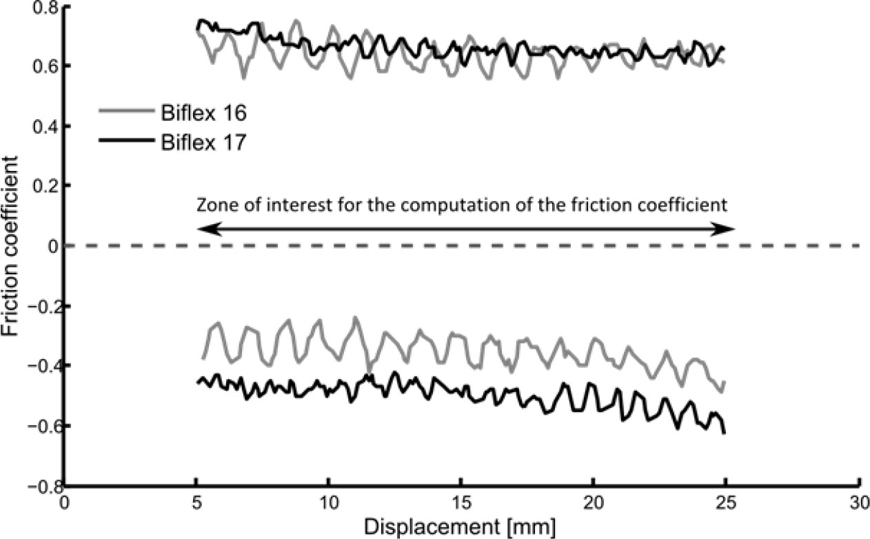
Examples of curves for two bandages samples B16 and B17, along the warp direction.
These experiments were not designed to investigate the impact of fabric structure on frictional properties. However, the measurements performed for the six bandages tend to be in agreement with a previous study [17], which noticed that an increase in fabric construction (i.e., the number of weft yarn per centimeter) led to an increase in the friction coefficient. Further investigations would be needed to conclude about a real impact of fabric structure on friction coefficient.
4.2 Influence of applied pressure
In the range of the tested applied pressures, very little changes in the friction coefficient were observed. Even if most of the changes were nonsignificant, increasing normal load seemed to result in a decrease of friction coefficient. This has already been observed by Ajayi [16] and Das et al. [4], where the relationship between the normal load and the frictional was found to be logarithmic. Here, the variability in the friction coefficient makes this logarithmic model impossible to verify and friction coefficient must be considered as constant.
4.3 Influence of fabric stretch
Contrary to applied pressure, stretch had an impact on bandage thickness. According to the tomographic images (Figure 1), the structure of the fabrics was subject to important changes along the warp direction but did not vary along the weft direction. Indeed, these bandages showed no Poisson effect once stretched (i.e., the width of the bandage remains stable whatever its stretch) as shown on Figure 1. However, stretching the fabric tended to decrease its density. It could have been expected that the friction coefficient decreased when stretch increased, as the number of weft yarn per cm decreased, but it was not the case. Figure 1 also clearly shows that stretching the fabric changed the period of the structure, but did not change the pattern. A simple geometrical model based on moiré description was built to quantify the average interaction area between the fabric with a 1.3 stretch (on the movable pad) and the one with variable stretch (from 1.1 to 1.5). This model shows that, because of the small pad dimension, the interaction area is almost constant independently of the stretch.
4.4 Limitations
In the present study, the frictional behavior of fabric was approximated with Amonton’s law. This represents a strong hypothesis as it is known that fabric frictional behavior is more complex. Nonetheless, this law is very commonly used in numerical simulation.
To compute the friction coefficient, the KES removed the first and last 5 mm of the translation (which corresponds to the initiation of the translation motion). Thus, the computed friction coefficient was the dynamic friction coefficient. This system did not permit to characterize the static fabric-to-fabric friction coefficient. Another limitation of the KES was the translation speed. Even though previous studies did not observe any significant effect of the sliding speed on the dynamic friction coefficient [16, 18], it was not possible to characterize the frictional properties at varying speeds with the KES.
The area of the friction contactor should be designed with regards to the weaving pattern of the fabric. If the pattern is too large, the friction contactor area has to be enlarged. This may be the cause of difficulties depending on the normal load, which would be required for the characterization. Indeed, increasing the contact area also means increasing the applied weight, which might disturb the translation motion of the KES.
Finally, the fabrics tested in the present study were mostly woven fabrics. But it was proven that the fabric structure and its fibers components impact on the friction coefficient [8, 19].
5 Conclusion
A simple and reliable method was designed to characterize the fabric-to-fabric friction coefficient of medical bandages used for compression therapy. This method, based on the surface tester of the KES enable the measurement of the friction coefficient for varying fabric stretches and normal loads and provided the frictional properties of compression bandages in use conditions. This method is not limited to bandage compression characterization but could be suitable for the characterization of the friction coefficient of other compression textiles.
References
[1] Ghosh, S., Mukhopadhyay, A., Sikka, M., Nagla, K. S. (2008). Pressure mapping and performance of the compression bandage/garment for venous leg ulcer treatment. Journal of Tissue Viability, 17(3), 82–94.10.1016/j.jtv.2007.09.013Suche in Google Scholar PubMed
[2] Gupta, B. S., (2008). Textile institute, editors. Friction in textile materials. CRC Press, Woodhead Publishing in Textiles (Cambridge), 462 p.Suche in Google Scholar
[3] Butler, K. J., Cowhig, W. T., Morris, W. J. (1955). A cloth profile recorder. Silk and Rayon Record.Suche in Google Scholar
[4] Das, A., Kothari, V. K., Vandana, N. (2005). A study of frictional characteristics of woven fabrics. AUTEX Research Journal, 5(3).10.1515/aut-2005-050303Suche in Google Scholar
[5] Ramkumar, S. S., Wood, D. J., Fox, K., Harlock, S. C. (2003). Developing a polymeric human finger sensor to study the frictional properties of textiles: part I: artificial finger development. Textile Research Journal, 73(6), 469–473.10.1177/004051750307300601Suche in Google Scholar
[6] Kawabata, S. (1980). The standardization and analysis of hand evaluation, 2nd edition. Textile Machinery Society of JapanSuche in Google Scholar
[7] Bertaux, E., Lewandowski, M., Derler, S. (2007). Relationship between friction and tactile properties for woven and knitted fabrics. Textile Research Journal, 77(6), 387–396.10.1177/0040517507074165Suche in Google Scholar
[8] Moorthy, R. R. (2015). Surface friction characteristics of woven fabrics with nonconventional fibers and their blends. Journal of Textile and Apparel, Technology and Management, 9(3).Suche in Google Scholar
[9] Ajayi, J. (1992). Effects of fabric structure on frictional properties. Textile Research Journal, 62(2), 87–93.10.1177/004051759206200205Suche in Google Scholar
[10] Ajayi, J. (1992). Fabric smoothness, friction, and handle. Textile Research Journal, 62(1), 52–59.10.1177/004051759206200108Suche in Google Scholar
[11] ISO 139:2005. (2005). Textiles – standard atmospheres for conditioning and testing.Suche in Google Scholar
[12] Chassagne, F., Martin, F., Badel, P., Convert, R., Giraux, P., et al. (2015). Experimental investigation of pressure applied on the lower leg by elastic compression bandage. Annals of Biomedical Engineering, 43(12), 2967–2977.10.1007/s10439-015-1352-1Suche in Google Scholar PubMed
[13] Harwood, R. J., Weedall, P. J., Carr, C. (2008). The use of the Kawabata Evaluation System for product development and quality control. Journal of the Society of Dyers and Colourists. 106(2), 64–68.10.1111/j.1478-4408.1990.tb01244.xSuche in Google Scholar
[14] Hu, J. (2004). Structure and mechanics of woven fabrics. Boca Raton, FL : Cambridge: CRC Press, Woodhead Pub, (Woodhead Publishing in textiles), 307 p.Suche in Google Scholar
[15] BIPM. (2008). International vocabulary of metrology – basic and general concepts and associated terms (VIM). JCGM, 200, 2008.Suche in Google Scholar
[16] Ajayi, J. O. (1992). Fabric smoothness, friction, and handle. Textile Research Journal, 62(1), 52–59.10.1177/004051759206200108Suche in Google Scholar
[17] Ajayi, J., Elder, H. (1997). Effects of surface geometry on fabric friction. Journal of Testing and Evaluation, 25(2), 182.10.1520/JTE11476JSuche in Google Scholar
[18] Hermann, D., Ramkumar, S. S., Seshaiyer, P., Parameswaran, S. (2004). Frictional study of woven fabrics: the relationship between the friction and velocity of testing. Journal of Applied Polymer Science, 92(4), 2420–2424.10.1002/app.20213Suche in Google Scholar
[19] Ajayi, J. O. (1992). Effects of fabric structure on frictional properties. Textile Research Journal, 62(2), 87–93.10.1177/004051759206200205Suche in Google Scholar
© 2020 Fanette Chassagne et al., published by Sciendo
This work is licensed under the Creative Commons Attribution 4.0 International License.
Artikel in diesem Heft
- Compressive Property of an Auxetic-Knitted Composite Tube Under Quasi-Static Loading
- Investigation of the Tribological Behaviors of Upholstery Woven Fabrics after Abrasion
- Microstructural Damage Characteristic of a Layer-to-Layer Three-Dimensional Angle-Interlock Woven Composite Under Quasi-Static Tensile Loading
- Initial Investigation Into Real 3D Body Scanning Versus Avatars for the Virtual Fitting of Garments
- Mathematical Model Predicting the Heat and Power Dissipated in an Electro-Conductive Contact in a Hybrid Woven Fabric
- A Method of 1D UVC Radiation Dose Measurement using a Novel Tablet Dosimeter
- Introducing a Newly Developed Fabric for Air Filtration
- A New Approach to Evaluate Fabric Hand Based on Three-Dimensional Drape Model
- Study on the use of Aerogel on the Surface of Basalt Fabric
- Analysis of Factors Affecting Thermal Comfort Properties of Woven Compression Bandages
- Country-Specific Determinants of Textile Industry Development in Poland: Comparative Analysis of the Years 2007 and 2017
- Comparative Study of Needle Penetration Forces in Sewing Hems on Toweling Terry Fabrics: Influence of Needle Type and Size
- Numerical and Experimental Comparative Analysis of Ballistic Performance of Packages Made of Biaxial and Triaxial Kevlar 29 Fabrics
- Characterization of Fabric-to-Fabric Friction: Application to Medical Compression Bandages