Gesture and force sensing based on dielectric elastomers for intelligent gloves in the digital production
-
Sebastian Gratz-Kelly
Sebastian Gratz-Kelly is a Ph D. student at the intelligent Material Systems Lab of the Saarland university. He received his B.Sc. in 2014 and M.Sc. in 2017 from Saarland University, Department of Systems Engineering. His main topic are sensor and actuator systems based on dielectric elastomers, smart textiles and textile integration as well as user interaction.

 ,
Daniel Philippi
,
Daniel Philippi

Abstract
Due to recent progress in human-machine interaction the development of interfaces ensuring a safe collaboration between handling devices and workers is gaining in importance and impact to the industry field. For an adequate operation, combined sensing and actuation capabilities are sufficient for interaction units. Smart materials like dielectric elastomers (DEs) are predestinated for integrated multi-functional applications. DEs are lightweight, high energy density and highly stretchable transducers suitable for many different operation areas, like movement tracking, force sensing, haptic feedback and sound generation and can be used to develop highly integrated textile-based user interfaces. This paper shows first results on the development of a novel intelligent glove prototype based on DE elements. The main focus of this investigation lies on DE-based integrated joint angle and force measurement units as well on a cost-efficient and slim sensing electronic. By embedding the resulting system in an Industry 4.0 environment, an adaptive assistance tool can be developed. The resulting system can be used to monitor the desired motion of a worker and to respond with a corresponding haptic feedback, which depends on the specific interaction task. This makes the resulting system a novel, portable assistant tool for industrial environments.
1 Introduction
In many different areas in the production line a communication possibility between a worker and the industry environment during the process chain is very important. On the one hand, it is necessary to give an easy-to-use and very intuitive possibility for information disclosure, on the other hand it is also important that the user of the assistance tool can get a feedback from the communication partners or the environment. For these requirements the characteristics of dielectric elastomers (DEs) promise a number of application scenarios. For the use in an interactive, haptic assistance tool, especially the combination of actuation and sensing is decisive. Additionally, the high energy density, flexible geometry, high inherent flexibility/stretch, simple structure and low weight [1] are characteristics that perfectly match the use in mobile usage and integration into textiles. In Figure 1, the possible features of the smart glove are presented. The presented assistance tool is intended to detect the motion of the worker and serve as an information assistant in the production environment. The information feedback to the worker can be haptic (e.g. vibration, force pulse), kinesthetic (e.g. restriction of certain degrees of freedom of the hand), visual or acoustic. The multifunctionality of DEs for user interaction are already proposed in [2], [3], where the DE is simultaneously used for sensing, haptic feedback (low-frequency actuation) and acoustic feedback (high-frequency actuation). In this paper, the main focus is on the sensing features of a smart glove. The two major interesting measurement variables are the hand position respectively gesture as well as the applied force, which is supplied to a component or tool, for example gripping forces, pushing forces or even torques. It is possible to calculate tightening forces and moments for screws or clamps. Another use case is to estimate a desired movement via the acting forces and give an intelligent help by the handling device. In addition, the measurement of grasping forces can give an assessment whether the ergonomic conditions are met. The finger movement and position can be important to classify and validate certain tasks of the worker or identify dangerous situations, like squeezing the fingers in a machine as well as ergonomic aspects of the worker activity.

Possible features of the smart glove.
Force measurement based on DEs has been already presented in the literature [4], [5], [6] and DE-based gesture and body movement sensing is developed in [7], [8], [9]. This paper presents an upscalable way to integrate sensors directly into textiles and develop an integrated low-cost electronics for the use with DE sensors based on cheap components proven in industrial environment. The DE sensors are mainly used as capacitive strain sensors, although it is possible to use the DE electrodes as resistance sensors, but this results in non-monotonic strain responses [10]. The concept of the sensing glove is validated with capacitance measurements of the single DE elements.
The integration of different DE-based elements in textiles has been demonstrated in [11], [12]. For sensor applications, different institutes are developing and researching textile integrated sensors, like the Research Center E. Piaggio, University of Pisa [13], the Department of Biomedical Engineering and Biomaterials, Queen Mary University of London [14], the Biomimetics Laboratory of the Auckland Bioengineering Institute [7], [8], [9], the John A. Paulson School of Engineering and Applied Sciences, Harvard University [15] and Kyushu Institute of Technology [16]. Many research articles deal with intelligent sensor gloves, but in most cases these are based on single sensors without textile-integrated, flexible and wearable electronics. In addition, the integration of sensors for gesture recognition and force recognition is not presented simultaneously and with correspondingly adapted common electronics. In [17], [18], [19], [20], [21], [22], [23], [24], [25], [26], [27], [28] different developed smart gloves are shown as example, [29] compares different commercially available smart gloves.
2 Functional principle of dielectric elastomer sensors
Dielectric elastomers consist of an elastomer membrane with flexible electrodes on each side of the membrane (Figure 2). Electrically a DE is a capacitor with flexible area and thickness. The capacitance can be calculated with:
where Q is the charge on the capacitor, U the voltage at the electrodes, ɛ 0 the vacuum permittivity and ɛ r the relative permittivity. A is the surface area of the electrode material and d is the thickness of the polymer dependent on a variation along the z-axis. There are different ways to use DE sensor properties for stroke and force measurement, by adapting the geometry and the mechanical setup of the subsystem, and even use them in actuator applications or for self-sensing [8], [30], [31].

Working principle of dielectric elastomer sensors: (a) DE construction, (b) deformation of the DE by external stimuli, (c) sensor configuration for measurement of stretch, force or angle.
For the dielectric material of the DE we used PDMS Elastosil 2030 film by Wacker, with initial thickness of 50 µm. The electrode material were made of PDMAS (SilGel 612 by Wacker) loaded with carbon black particles (Orion Printex XE2) applied to the silicone-film by screen-printing [32]. In practice, the flexible electrodes have a relatively high resistance, which affects the performance and sensor behavior of the DE [32], [33]. The equivalent circuit diagram of a dielectric elastomer is accordingly, in a simplified way, a capacitance in series with a resistor. The parallel membrane resistor is on the order of several MΩ and can be neglected. In Figure 3, the resulting equivalent circuit of a DE sensor is shown. The serial resistor of the DE R s represents the surface resistance of the flexible electrode and the contact resistance of the electrical connections. The serial resistance of the used carbon black electrodes is in the region of several kΩ depending on the geometry and the manufacturing process. The capacitance of an ideal DE can be calculated by the geometry-depending Equation (1). Due to the relatively high resistance of the electrode material a real DE can not be sufficiently modeled with a simple RC circuit. A better representation of the real DE can be achieved by cascading more RC circuits in series [34], [35].

Equivalent circuit of DE sensor with (a) simplification of the basic DE structure and (b) a cascade of the simplified RC circuits.
For a model of three RC elements like in Figure 3(b) the impedance can be calculated for symmetric model values (R = R DE1 = R DE2 = R DE3 and C = C DE1 = C DE2 = C DE3 ) with:
Equation (2) shows that even for a relatively easy assumption of a DE model, with just three separation levels, the electrical behavior of a DE is not trivial, which also leads to difficulties for the electronic measurement of the DE capacitance. With that in mind, the capacitance measured with standard measurement equipment (which is accurate for an ideal capacitance) is an approximation of a simplified DE model.
3 Design of the intelligent glove
The developed glove consists of two different types of DE sensors. Stretch sensors are used for sensing of the joint angles of the fingers and DE based force sensors are used to measure the gripping or handling force of the user. The two different sensor types require different constructional and mechanical boundary conditions and manufacturing processes. For this reason the design, functional principle and manufacturing is presented in the following.
3.1 Design of gesture recognition sensors
For the recognition of single finger joints a selection of the most important finger joints is measured. The human hand itself has already all together 29 degrees of freedom (with free space positioning of the hand) [36]. To reduce the complexity of the sensor layout, but still measure the most important positions of the fingers, nine finger joints are individually measured. For the nine sensors a separate sensing-electrode and two ground electrodes are designed in a way that they exactly overlap at the areas where the joints of the fingers are measured. With the used electrode design it is possible to sense more single sensors with less electrical connections like a sensor matrix element (compare [37]). The absolute position of the hand in space can be measured with an inertial measurement unit (IMU) which can be placed at the backhand of the glove for example.
To increase the capacitance change of the DE and additionally shield the DE electrode from surrounding interferences, a ground layer is applied on both sides. In Figure 4, the structure of the glove with three DE layers and specifically adapted sensing electronics is shown. The three layers are glued together during the screen-printing process. The electrodes are designed in a way that they fit to the desired joint positions of the hand and the connection lines are realized by screen-printed carbon black electrode material.

Structure of the sensing glove with three-layer DE and matching electronics.
Compared to other solutions in literature we use one single low-cost sensing electronic system with multiplexers to switch between the different sensors. By using a DE design with two different ground areas it is possible to use only five connection pads between the DE electrodes and the electronics board and small size multiplexers to measure all nine joints.
With this procedure, a manufacturing process for the DE element itself and the layering of more elements as well as the connections to the electronics is possible. Furthermore, with a similar procedure, the DE stack can be directly applied onto a textile. In that case, the textile (80 % polyamide, 20 % elastane; 210 g/m2) first gets pre-laminated with an adhesive layer and then the staked DE element is bonded to the textile.
During the manufacturing it is also possible to integrate electrical connections and electrical boards to the silicone film. By using flexible printed circuit boards (PCB) they can be connected with a conductive adhesive connection. With the flexible connection it is possible to reduce the mechanical stress in the electrical contact. Additionally, a silicone film can be added to further reduce the mechanical stress and realize an independent mechanical and electrical connection. Due to the very low thickness of the DE element (around 150–170 µm) it is possible to integrate the DE element and the textile to a composite. In Figure 5, the production process of a textile integrated DE sensor is shown.

Textile integration of DE based sensing element.
3.2 Design of force sensors
A second sensing component to complement the glove are force sensing elements. These elements can be integrated at different regions in the inner hand part of the glove. Depending on the position either gripping forces or pushing forces, i.e. the processing forces of working steps, can be measured. For force sensing, different concepts are developed and compared [5]. For the integration into the glove a structure shown in Figure 6, designed in a similar way to [6], [38], is used. It is not possible to directly measure the force exerted on the DE, which means that it is always necessary to convert the exerted force into a deformation. Depending on the mechanism used to transfer the applied force into a measurable deformation, the system behavior changes [5]. In the force sensors used, a mechanism for converting the force applied to the electrode surface into a change in the strain of the DE is realized by using interlocking silicone structures on the DE electrode (Figure 6(a)). The force range can be adjusted by changing the geometry of the interlocking silicone structure (e.g. height h of the structure elements and radial distance of the structures Δr) which is applied to electrodes of the DE

Force measurement sensor based on DEs with possibility of directional force measurement. With (a) design and pictures of the force sensor with interlocking silicone structure and (b) electrode design for four segment sensor with picture and marked sensor areas.
By structuring the electrode it is possible to also detect the direction of the applied force. With a 4-segment electrode (see Figure 6(b)) it is possible to detect which segment is pressed more than the others to calculate the force direction. The integration of the force sensors can be done in a similar way like for the joint angle sensors (Figure 5). In addition, the interlocking silicone structure for the specific force-deformation transformation has to be integrated. Firstly, the interlocking silicone structure was glued to the textile part at the desired position and afterwards the DE layers was adhered to the textile and the silicone structure. In a last step the second part of the silicone structure is applied to the silicone film. In that way it is possible to integrate the force sensors during the lamination of the DE elements to the textile.
3.3 Electronics design
The electronics design is shown in Figure 4. With a different electrode shape for the ground electrode and the sensing electrode it is possible to lower the needed number of electrical connections from the DE to the sensing electronic (Figure 4). Two multiplexers switch between the different sensors. One multiplexer just switches between two states of the ground electrode to change between the metacarpophalangeal joint (first/lower joint) and the proximal interphalangeal joint (second/middle joint) of the specific fingers, the second multiplexer differentiates between the single five fingers. To realize a real – time measurement of the all nine sensors, the electronics needs to be able to measure every single sensor in less than three ms.
The capacitance measurement itself is realized with a custom electronics based on inexpensive, commercially available and reliable components. The capacitance-sensing measurement concept is based on cyclic charging and discharging time measurement. In Figure 7, the corresponding equivalent electric circuit is shown. The DE is charged and discharged over a loading resistor. In the picture, C DE,N represents the partly defined DE capacitance (variable) and R DE,N the surface resistance of the electrodes and R 1, R 2 are resistors involved in the charging/discharging phases of the sensing cycle respectively, U supp is a constant voltage provided by a supply source. To simplify the circuit diagram, the real DE equivalent circuit is considered to be a simple capacitance.

Capacitance measurement principle with (a) equivalent circuit and (b) charging and discharging time measurement.
The DE sensor is cyclically charged to voltage U max and then discharged to voltage U min (with U min < U max < U supp ), and the duration t r of the resulting cycle time as sum of charging time t c and discharging time t d , t r = t c + t d is measured. By varying geometry and thickness due to stretch or deformation of the DE, the capacitance of the DE changes and the resulting time t r for the full charge-discharge cycle also changes. The current flowing in the circuit during the charging transient is
where t is time, U min the voltage on the DE at t = 0 and I(t) = (U supp − U min)/R 1 the initial current.
The charging time is calculated by setting
corresponding to a condition where the voltage on the DE sensing layer is U max, which leads to:
Similarly, the discharging time during which the DE voltage is decreased from U max to U min through resistor R 2 is
The total cycle time is thus proportional to C DE :
While in practice more complicated relationships between t r and C DE might apply (owing, e.g., to the DE’s compliant electrode resistance with a more complex DE circuit like Figure 7), a monotonic relationship between cycle time t r and capacitance C DE is expected to hold. The DE is combined with electronics that produce an frequency dependent PWM output signal where the output frequency is inversely proportional to the cycle time t r [3].
To integrate the sensing-electronics, peripheral elements like programing units, voltage supply and a battery are needed. These components are integrated in a flexible silicone housing with additional flexible PCB connections. The silicone housing can be integrated into the glove shaft or worn like a wristband. The silicone frame is casted in two parts in a mold, adapted to the electronics, and can be glued together to fix the single electronics elements.
Figure 8 shows the construction of the electronics assembly and integration into the silicone frame. Two similar sensor electronic components can be used for the backhand (stretch sensors for finger position measurement) and the palm of the hand (force measurement).
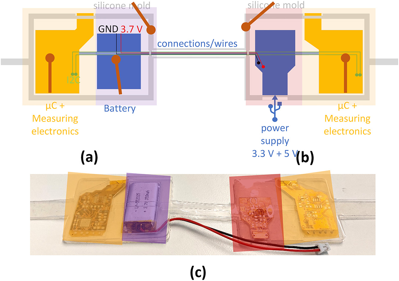
Electronics assembly with silicone holder, battery, voltage supply and programming unit and sensing-electronic. (a) Measurement unit with battery element, (b) power supply and second measurement unit and (c) picture of assembled electronics with silicone holder.
4 Test rig design and measurement results
4.1 Test rig
To measure the movement of the glove in a repeatable and controllable way a specific test rig for the joint angle measurements was designed (Figure 9). For that the used glove is fixed to a 3D-printed element based on thermoplastic polyurethane (TPU) material. With the flexible material and 3D-printed fixing elements specific joints of the glove can be deformed correspondingly to the human anatomy. The clamping elements for each finger can be connected to a motor, which pulls on cables to move the finger down. The amount of movement can be controlled by the rotation angle of the motor (NEMA 17 with 0.9° per step).

Test rig setup for (a) hand movement sensors and (b) force sensors of the glove.
To evaluate the real angle of the desired joint a camera ESP32-CAM Development Board with OV2640 camera module by APKLVSR is used with image processing to recalculate the actual angle of the joint (processed with Matlab). To realize a synchronous and symmetric movement of the finger joints, springs are integrated to pull the finger back to the original position. To control the motor and the sensing-electronic a corresponding validation unit is included in a 3D-printed housing.
For the DE-based force sensors a linear motor (Aerotech ANT – 25 LA) with a 10 N load cell KD40s (ME – Meßsysteme) is used to measure the force applied to the sensor. The DE element is clamped with a 3D-printed frame and the deformation is measured by the axis position validated by the linear motor directly. The force measurement test rig is controlled via a National Instruments FPGA programmed with LabView.
4.2 Results
To evaluate the ability of the prototype to measure the finger movements and gestures, measurements for the different fingers are performed. The motor is pulling on one finger and all sensors are measured in real time with the custom-made electronics. The multiplexer is switching at 500 Hz and can measure all joint data within 18 ms. The measurement values are filtered with a moving average filter (Matlab smooth()-function with a span of 2.5 % of the total number of data points and ‘rloess’ smoothing method).
In Figure 10, an exemplative measurement of the different sensors for a movement of the index finger (proximal interphalangeal joint) can be seen. It can clearly be seen that the movement of the index finger can be fitted to the measured angle with the camera. The other sensors are staying constant. Only the second sensor for the index finger (metacarpophalangeal joint) is slightly influenced by the movement of the finger, which leads to a change in the measured capacitance value. The signal of the base joint can be explained by the stretch supplied to the textile by the deformation of the respective finger middle joint.

Exemplative capacitance measurement of nine hand joints (5 base joints + 4 saddle joints) for a moving angle of 50° on the index finger. With the measured capacitance of (a) the pinky middle joint, (b) the ring finger middle joint, (c) the middle finger middle joint, (d) the motor trajectory measured with the camera and the index finger middle joint capacitance, (e) tumb base joint measurement and (f) the base joint measurements for the fingers (ring, middle and index finger) and the thumb saddle joint.
Table 1 presents the capacitance change during the measurement for all measured joints. On the diagonal the capacitance change of the articulated joint is set to 100 % and the measured difference for the not articulated finger joints is additionally shown. The capacitance difference is measured by taking the mean value of the capacitance for a time period before the actuation and subtract it from the mean value of the capacitance in the complete elongated state for the same time frame.
Measurement for all articulated finger joints with relative ΔC (compared to ΔC of the articulated sensor) and absolute change of the not articulated finger joints. The vertical axis represents the cause (moving joint) and the horizontal axis represents the measured axis (measured capacity at the respective sensor). Darker shading means higher measured capacitance values.

|
The value for the capacitance change of the not articulated joints is measured with the same two time frames. It can be seen that for the actuation of the middle joints only a noticeable capacitance change of the corresponding base joints at the same finger appears. The capacitance change of the other elements is always below 10 % of the deformed sensor. These capacitance changes can be explained by the stretch field, which is applied to the textile and are a combination of real stretch of the sensors and noise of the electric measurement.
The mechanical stretch of the whole textile-silicon composite has a much higher influence by articulating the respective base joints. This can be further influenced by the change of the lead resistance to the measured sensor if the base sensor is deformed. With these two influence parameters, the recalculation of the exact joint positions is more complicated by deforming the base joints of the fingers. In a real application not a single joint is moved but a gesture or movement of the whole hand is performed. In this case, the stress in the deformed area of the base joint will be reduced and also the incorrect measurements are dropping.
For the force measuring sensor, different geometries had been compared to show that the force behavior can be influenced and fitted to the specific need. Additionally, the pre-stretch of the silicone membrane has an influence to the sensor behavior. In Figure 11, the capacitance for different geometries and pre-stretches of the DE membrane is displayed. Presented are the mean values of 3 measurements each. It is to be expected that the measurable force will be higher for higher pretensions of the silicone membrane and that the force will also increase when the gap of the intersection silicone structures becomes narrower. Increasing the height of the silicone structure should increase the linear range and thus the overall measurement range of the sensors. The force is larger for smaller space between the interlocking silicone structure elements on the opposite side of the DE membrane (compare with Figure 6). The sensitivity for the quasi-linear region is higher with higher pre-stretch. If the silicone structure is completely pressed into the negative (lower) part of the silicone structure (deformation > h; see Figure 6) the sensitivity decreases and the force increases significantly. The different geometries are characterized by the radial distance between the structural elements (in this case 0.75 mm; 1.5 mm; and 2.25 mm distance) which corresponds to Δr in Figure 6.

Influence oft the structure geometry and pre-stretch of the DE membrane to the capacitance-force performance. (a) 30 % biaxial pre-stretch and (b) 20 biaxial pre-stretch of the membrane. The different structure values characterize the distance Δr between the intersection structures on opposite side of the DE.
Moreover, by using structured/patterned electrodes (see Figure 6) the direction of the force respectively the pressed area can be determined. Therefore, in the test setup a plunger, moved by a linear motor, presses just on one element of the four-segmented DE sensors. All four segments of the sensor are read out and simultaneously the applied force is recorded with a load cell.
In Figure 12(a) and (b), the deformation profile of the motor and the resulting force measured with the load cell is illustrated. For the one segment, which is directly deformed, the force-displacement and displacement-capacitance curves are shown. In the force measurement, a stiffness kink when reaching the sensor ‘end position’, can be recognized at an indentation of approximately 2.8 mm. However, due to the flexibility of the covering silicone and the resulting deformation of the DE membrane the force can be further increased and measured also after reaching the ‘end position’ of the sensor. This can either be used to specifically choose the height of the silicone structures in a way that two stiffness regions can be applied to the sensor (for example a high sensitive region for finer working steps and a region were macroscopic gripping forces are measured) or the higher stiffness region can be used as a safety region to not break the sensor by applying higher forces.

Measured deformation of one segment of the force sensor with (a) force and deformation of the pressed sensor segment and (b) capacitance change for the pressed segment and comparison with the capacitance change of the three other segments. (c) Capacitance variation for different geometries and pre-stretch of the silicone foil for different sensors.
The capacitance change of the not directly deformed segments are around 12 % of the capacitance change of the pressed segment (for a maximum force of 10 N), which can be explained by the slight deformation of the whole sensor. The capacitance change of the undeformed segments reaches a plateau at deformations higher than the appeared force kink, because the upper and lower silicone frames are pressed together and the resulting deformation of the structure itself is negligible. In Figure 12(c) the capacitance change of different sensors with different geometries and pre-stretch of the DE membrane are compared. The capacitance change increases with higher pre-stretch and decreases with higher gaps between the silicone structure. The capacitance variation is shown in a boxplot with median (red line) and lower and higher quartile (blue box).
5 Conclusions
We described the development of an integrated sensory glove with different sensor structures. The focus of the development is the manufacturability, low cost and robust construction as well as a custom made integrated, low cost electronics. The design of the dielectric elastomer sensors is fitted to the geometry of the glove and can be adapted to other body parts. The manufacturing process for the DE-textile composite is presented and can be implemented during the standard production process of DEs. To show the functionality and validate the performance of the glove and the electronics, measurements of the sensors are described. With the developed sensors and electronics it is possible to detect the finger position with 9 joint angles in real-time speed and forces in different customizable force ranges from low forces to higher forces (several 10 N).
With the further integration of actuators for haptic feedback for example, a unique interaction interface and assistance tool could be realized. With the shown concepts, manufacturing processes and developments, textile-integrated sensors and actuators for many different applications are feasible and the user interaction can be more intuitively designed.
Funding source: European Union’ EFRE research and innovation program
Award Identifier / Grant number: VProSaar
Award Identifier / Grant number: iSMAT
About the authors

Sebastian Gratz-Kelly is a Ph D. student at the intelligent Material Systems Lab of the Saarland university. He received his B.Sc. in 2014 and M.Sc. in 2017 from Saarland University, Department of Systems Engineering. His main topic are sensor and actuator systems based on dielectric elastomers, smart textiles and textile integration as well as user interaction.

Daniel Philippi is student researcher at the intelligent Material Systems Lab of the Saarland University. He received his B.Sc. in 2023 from Saarland University, Department of Systems Engineering. His main topic are sensor systems based on dielectric elastomers.

Bettina Fasolt graduated with a master degree in chemical engineering from TU Berlin in 1993. After graduation, she worked with DEPOGAS and Ingea Tec, Berlin, and from 2001, as senior chemist with Redox Tech, Cary, USA. In 2013, she joined the Center for Mechatronics and Automation Technologies (ZeMA), Saarbrücken, where she has been director of cleanroom operations and material development since 2016. Her main research focus is on the development of DE membrane sensors and actuators and their experimental characterization.

Dr.-Ing. Sophie Nalbach is the Head of the research division “Smart Material Systems” at the Center for Mechatronics and Automation Technology (ZeMA gGmbH) in Saarbrücken, Germany. At Saarland University, Germany, she graduated with a B.Sc., M.Sc. and PhD degrees in Mechatronics and Systems Engineering. The focus of her PhD thesis at the intelligent Material Systems Lab was on dynamic applications based on dielectric elastomers. Her current research includes smart materials, e.g., electroactive polymers and shape memory alloys, in actuator-sensor systems.

Prof. Dr.-Ing. Paul Motzki is the Director of the research division “Smart Material Systems” at ZeMA, Saarbrücken, Germany. He received his PhD degree in Systems Engineering from Saarland University in 2018. In 2022, he was appointed the professorship “Smart Material Systems for innovative Production” by the Department of Systems Engineering of Saarland University. He is the Chair of the VDI/VDE Technical Committee GMA 2.16: “Smart Materials and Systems”, Director on the board of ASM SMST, Senate Member of AMSE SMASIS.
Acknowledgments
The Authors thank Tobias Willian for manufacturing support of the sensing elements and Bendikt Holz and Thomas Würtz for support of the electronic development. We thank Prof. Dr. Stefan Seelecke for his expertise and useful discussions.
-
Research ethics: Not applicable.
-
Author contributions: S.G. designed the sensors and system structure. S.G. and B.F. manufacture the sensing elements and textile integration. S.G. and D.P. designed the test setup and performed the experiments and computation. P.M. and S.N. acquired the founding and supervised the project. S.G took lead in writing the manuscript, P.M. and S.N. reviewed the first manuscript draft. All authors discussed the results and contributed to the final manuscript.
-
Competing interests: The authors states no competing interests.
-
Research funding: Promotionskolleg – Digitalisierung der Produktion and EFRE: VProSaar, iSMAT.
-
Data availability: The raw data can be obtained on request from the corresponding author.
References
[1] A. York, et al.., “Towards self-sensing of DEAP actuators: capacitive sensing experimental analysis,” in Proc. of the ASME 2010 Conf. on Smart Materials, Adaptive Structures and Intelligent Systems. Volume 1. Philadelphia, PA, USA, 2010. pp. 307–314. https://doi.org/10.1115/SMASIS2010-3847.Search in Google Scholar
[2] S. Gratz-Kelly, G. Rizzello, M. Fontana, S. Seelecke, and G. Moretti, “A multi-mode, multi-frequency dielectric elastomer actuator,” Adv. Funct. Mater., vol. 32, no. 34, pp. 1–12, 2022, https://doi.org/10.1002/adfm.202201889.Search in Google Scholar
[3] S. Gratz-Kelly, T. Krüger, G. Rizzello, S. Seelecke, and G. Moretti, “An audio-tactile interface based on dielectric elastomer actuators,” Smart Mater. Struct., vol. 32, no. 3, p. 034005, 2023. https://doi.org/10.1088/1361-665X/ACB6DA.Search in Google Scholar
[4] P. Loew, et al.., “Pressure monitoring inside a polymer tube based on a dielectric elastomer membrane sensor,” in SPIE Smart Structures + Nondestructive Evaluation, Electroactive Polymer Actuators and Devices, 2018, p. 53.10.1117/12.2296332Search in Google Scholar
[5] S. Gratz-Kelly, et al.., “Force measurement based on dielectric elastomers for an intelligent glove providing worker assessment in the digital production,” in SPIE Smart Structures + Nondestructive Evaluation, Electroactive Polymer Actuators and Devices, SPIE, 2020, pp. 242–251.10.1117/12.2558442Search in Google Scholar
[6] H. Böse, et al.., “Applications of pressure-sensitive dielectric elastomer sensors,” in SPIE Smart Structures + Nondestructive Evaluation, Electroactive Polymer Actuators and Devices, vol. 9798, 2016, p. 97982C.10.1117/12.2220808Search in Google Scholar
[7] A. D. W. Orbaugh, et al.., “The challenges of hand gesture recognition using dielectric elastomer sensors,” in SPIE Smart Structures + Nondestructive Evaluation, Electroactive Polymer Actuators and Devices, SPIE, 2020, pp. 231–241.10.1117/12.2558388Search in Google Scholar
[8] B. O’Brien, et al.., “Stretch sensors for human body motion,” in SPIE Smart Structures + Nondestructive Evaluation, Electroactive Polymer Actuators and Devices, Y. Bar-Cohen, Ed., 2014, p. 905618.10.1117/12.2046143Search in Google Scholar
[9] C. R. Walker, et al.., “Monitoring diver kinematics with dielectric elastomer sensors,” in SPIE Smart Structures + Nondestructive Evaluation, Electroactive Polymer Actuators and Devices, SPIE, 2017, pp. 11–21.10.1117/12.2260394Search in Google Scholar
[10] J. Mersch, H. Winger, A. Nocke, C. Cherif, and G. Gerlach, “Experimental investigation and modeling of the dynamic resistance response of carbon particle-filled polymers,” Macromol. Mater. Eng., vol. 305, no. 10, p. 2000361, 2020. https://doi.org/10.1002/MAME.202000361.Search in Google Scholar
[11] D. De Rossi, F. Carpi, and F. Galantini, “Functional materials for wearable sensing, actuating and energy harvesting,” Adv. Sci. Technol., vol. 57, pp. 247–256, 2008. https://doi.org/10.4028/www.scientific.net/AST.57.247.Search in Google Scholar
[12] F. Carpi and D. DeRossi, “Electroactive polymer-based devices for e-textiles in biomedicine,” IEEE Trans. Inf. Technol. Biomed., vol. 9, no. 3, pp. 295–318, 2005. https://doi.org/10.1109/TITB.2005.854514.Search in Google Scholar PubMed
[13] D. De Rossi, et al.., “Electroactive fabrics and wearable biomonitoring devices,” AUTEX Res. J., vol. 3, no. 4, pp. 180–185, 2003. https://doi.org/10.1515/aut-2003-030404.Search in Google Scholar
[14] G. Frediani, L. Bocchi, F. Vannetti, G. Zonfrillo, and F. Carpi, “Wearable detection of trunk flexions: capacitive elastomeric sensors compared to inertial sensors,” MDPI – Sensors, vol. 21, no. 16, p. 5453, 2021. https://doi.org/10.3390/s21165453.Search in Google Scholar PubMed PubMed Central
[15] A. Atalay, et al.., “Batch fabrication of customizable silicone-textile composite capacitive strain sensors for human motion tracking,” Adv. Mater. Technol., vol. 2, no. 9, p. 1700136, 2017. https://doi.org/10.1002/ADMT.201700136.Search in Google Scholar
[16] N. Kumar Singh, et al.., “Dielectric elastomer based stretchable textile sensor for capturing motion,” in SPIE Smart Structures + Nondestructive Evaluation, Proceedings Volume 11375, Electroactive Polymer Actuators and Devices (EAPAD) XXII, SPIE, 2020, pp. 301–308.10.1117/12.2565743Search in Google Scholar
[17] T. Linn, et al.., “Smart glove for visually impaired,” in Computing Conference, London, 2017, pp. 1323–1329.10.1109/SAI.2017.8252262Search in Google Scholar
[18] C. Scheuermann, et al.., “Increasing the support to humans in factory environments using a smart glove: an evaluation,” in IEEE Conferences on Ubiquitous Intelligence & Computing, Advanced and Trusted Computing, Scalable Computing and Communications, Cloud and Big Data Computing, Internet of People, and Smart World Congress, 2016.10.1109/UIC-ATC-ScalCom-CBDCom-IoP-SmartWorld.2016.0134Search in Google Scholar
[19] T. M. Vu, et al.., “Smart glove for augmented and virtual reality,” IJITIS, vol. 4, no. 2, pp. 663–671, 2021. https://doi.org/10.15157/IJITIS.2021.4.2.663-671.Search in Google Scholar
[20] M. Zhu, et al.., “Haptic-feedback smart glove as a creative human-machine interface (HMI) for virtual/augmented reality applications,” Sci. Adv., vol. 6, no. 19, pp. 1–14, 2020, https://doi.org/10.1126/SCIADV.AAZ8693/SUPPL_FILE/AAZ8693_SM.PDF.Search in Google Scholar
[21] L. Santos, et al.., “Dynamic gesture recognition using a smart glove in hand-assisted laparoscopic surgery,” MDPI – Technologies, vol. 6, no. 6, p. 8, 2017. https://doi.org/10.3390/technologies6010008.Search in Google Scholar
[22] Y. Luo, et al.., “Triboelectric bending sensor based smart glove towards intuitive multi-dimensional human-machine interfaces,” Nano Energy, vol. 89, p. 106330, 2021. https://doi.org/10.1016/j.nanoen.2021.106330.Search in Google Scholar
[23] W. Dong, L. Yang, and G. Fortino, “Stretchable human machine interface based on smart glove embedded with PDMS-CB strain sensors,” IEEE Sens. J., vol. 20, no. 14, pp. 8073–8081, 2020. https://doi.org/10.1109/JSEN.2020.2982070.Search in Google Scholar
[24] Y. Zou, D. Wang, S. Hong, R. Ruby, D. Zhang, and K. Wu, “A low-cost smart glove system for real-time fitness coaching,” IEEE Internet Things J., vol. 7, no. 8, pp. 7377–7391, 2020. https://doi.org/10.1109/JIOT.2020.2983124.Search in Google Scholar
[25] K. Niazmand, et al.., “Quantitative evaluation of Parkinson’s disease using sensor based smart glove,” in 2011 24th International Symposium on Computer-Based Medical Systems (CBMS), Bristol, UK, 2011, pp. 1–8.10.1109/CBMS.2011.5999113Search in Google Scholar
[26] N. Praveen, et al.., “Sign Language interpreter using A smart glove,” in International Conference on Advances in Electronics, Computers and Communicators, Bangalore, 2014.10.1109/ICAECC.2014.7002401Search in Google Scholar
[27] B. O’Flynn, et al.., Novel Smart Glove Technology as a Biomechanical Monitoring Tool, [Online], 2015. Available at: https://www.sensorsportal.com/HTML/DIGEST/P_2731.htmhttp://www.sensorsportal.com.Search in Google Scholar
[28] C. Tushar, et al..,“Smart glove with gesture recognition ability for the hearing and speech impaired,” IEEE Global Humanitarian Technology Conf. - South Asia Sate (GHTC-SAS), Trivandrum, India, 2014, pp. 105–110.10.1109/GHTC-SAS.2014.6967567Search in Google Scholar
[29] M. Caeiro-Rodríguez, I. Otero-González, F. A. Mikic-Fonte, and M. Llamas-Nistal, “A systematic review of commercial smart gloves: current status and applications,” MDPI- Sensors, vol. 21, no. 8, p. 2667, 2021. https://doi.org/10.3390/s21082667.Search in Google Scholar PubMed PubMed Central
[30] D. Pyo, S. Ryu, K. U. Kyung, S. Yun, and D. S. Kwon, “High-pressure endurable flexible tactile actuator based on microstructured dielectric elastomer,” Appl. Phys. Lett., vol. 112, no. 6, p. 1–5, 2018, https://doi.org/10.1063/1.5016385.Search in Google Scholar
[31] G. Rizzello, D. Naso, A. York, and S. Seelecke, “A self-sensing approach for dielectric elastomer actuators based on online estimation algorithms,” IEEE/ASME Trans. Mechatron., vol. 22, no. 2, pp. 728–738, 2017. https://doi.org/10.1109/TMECH.2016.2638638.Search in Google Scholar
[32] B. Fasolt, M. Hodgins, G. Rizzello, and S. Seelecke, “Effect of screen printing parameters on sensor and actuator performance of dielectric elastomer (DE) membranes,” Sens. Actuator A Phys., vol. 265, pp. 10–19, 2017. https://doi.org/10.1016/J.SNA.2017.08.028.Search in Google Scholar
[33] B. Fasolt, et al.., “Characterization of screen-printed electrodes for dielectric elastomer (DE) membranes: influence of screen dimensions and electrode thickness on actuator performance,” in SPIE Smart Structures + Nondestructive Evaluation and Health Monitoring, Electroactive Polymer Actuators and Devices, 2016, p. 97983E.10.1117/12.2222095Search in Google Scholar
[34] D. Xu, A. Tairych, and I. A. Anderson, “Localised strain sensing of dielectric elastomers in a stretchable soft-touch musical keyboard,” in SPIE Smart Structures + Nondestructive Evaluation, Electroactive Polymer Actuators and Devices, vol. 9430, 2015, p. 943025.10.1117/12.2084770Search in Google Scholar
[35] D. Xu, S. Michel, T. McKay, B. O’Brien, T. Gisby, and I. Anderson, “Sensing frequency design for capacitance feedback of dielectric elastomers,” Sens. Actuator A Phys., vol. 232, pp. 195–201, 2015. https://doi.org/10.1016/j.sna.2015.05.010.Search in Google Scholar
[36] S. Gratz-Kelly, et al.., “Intelligente Handschuhe zur Werkerunterstützung in der digitalisierten Produktion,” in Dritte transdisziplinäre Konferenz Technische Unterstützungssysteme, die die Menschen wirklich wollen 59, Hamburg, Helmut-Schmidt-Universität, 2018, pp. 59–66.Search in Google Scholar
[37] A. Meyer, et al.., “Experimental characterization of a smart dielectric elastomer multi-sensor grid,” in SPIE Smart Structures + Nondestructive Evaluation, Electroactive Polymer Actuators and Devices, SPIE, 2020, pp. 262–268.10.1117/12.2558433Search in Google Scholar
[38] H. Böse, et al.., “Operation tools with dielectric elastomer pressure sensors,” in Proceedings Volume 10163, Electroactive Polymer Actuators and Devices (EAPAD), Oregon, SPIE Smart Structures and Materials + Nondestructive Evaluation and Health Monitoring, 2017, p. 1016309.10.1117/12.2261494Search in Google Scholar
© 2024 the author(s), published by De Gruyter, Berlin/Boston
This work is licensed under the Creative Commons Attribution 4.0 International License.
Articles in the same Issue
- Frontmatter
- Editorial
- Editorial
- Research Articles
- Textile-based piezoelectric impact sensors for fibre-reinforced plastic composites
- Textile-based strain sensors for fiber-reinforced composites under tension, compression and bending
- Distributed fiber optic sensors for structural health monitoring of composite pressure vessels
- Temperature-dependent calibration and temperature compensation of elastic shape-memory alloy strain sensors for fiber-reinforced composite applications
- Gesture and force sensing based on dielectric elastomers for intelligent gloves in the digital production
- What kind of phonation causes the strongest vocal fold collision? – A hemi-larynx phonation contact pressure study
- Concept studies and application development of textile integrated dielectric elastomer sensors for smart shoe technologies