Damage detection of three-dimensional braided composite materials using carbon nanotube thread
-
Zhenkai Wan
 ,
Jianmin Guo
,
Jianmin Guo

Abstract
Structural health monitoring (SHM) takes advantage of the recent advances in structural behavior monitoring to assess the performance of a structure, identifying the damage in the early stage. In this study, a carbon nanotube thread strain sensor was fabricated into a three-dimensional (3D) braided composite preform for the strain sensing of SHM. We present the results of an investigation on a carbon nanotube thread network in 3D composites for damage detection, in which the variation of the electrical resistance of the carbon nanotube thread embedded into 3D composites was recorded. Based on the variation of the electrical resistance, the location and size of damages were estimated by the response surface method, providing an effective solution for the estimation of the location and size of damages in 3D composites.
1 Introduction
Three-dimensional (3D) braided composites have excellent out-of-plane mechanical properties, low delamination tendency, high-energy absorbing capability and outstanding fatigue resistance [1, 2], which make them strong candidates in the fields of aerospace industry, automobile industry and biomedical engineering. Furthermore, the most attractive of the 3D braided method is the net-shape capability to manufacture composites with special geometric shapes. The improved performance enables 3D composites to outweigh their relatively high costs. However, there are a variety of damage modes in 3D braided composites which are more complex than the well-known ones in conventional metal alloys. Furthermore, damage which typically occurs in the much earlier life of a structure is usually invisible in material. Therefore, it is critical for the development of structural health monitoring (SHM) diagnostics [3].
Carbon nanotubes (CNTs) were used as in situ sensors to detect the initiation of micro-cracks and their accumulation in fiber-reinforced polymer composites [4]. The electrically conductive networks formed by CNTs throughout the polymer matrix are dispersed in composites, the breakage of which enables the micro-cracks to be sensed. This methodology is applied to 3D braided composites with the aim of investigating the feasibility of the matrix failure detection and analysis of the damage behavior.
At present, the popular sensors embedded in composite materials contain piezoelectric crystals, fiber optic cables and piezoresistive sensors [5]. Optical fibers can either be embedded inside the composite structure or bonded on its surface, but the strain gauge can only be attached on the surface of the composite structure and cannot be embedded within it. While these sensors can be used for SHM, they themselves add stress concentrations in the composites, which in turn lead to failure of the material more quickly than if the sensors are not embedded in the first place. To mitigate this effect, the carbon fiber itself has been used as a piezoresistive sensor in continuous fiber composites.
Self-sensing methods have been applied to fatigue damage detection by several researchers [6, 7]. All applied processes are similar to the monotonic tensile test to measure the change in electrical resistance in carbon fiber reinforced plastic (CFRP) specimens. These tests are applied to unidirectional CFRP and cross-ply CFRP laminates. A decrease in electrical conductivity could be related to carbon fiber breakage. The electrical resistance increased with a decrease in specimen stiffness. The increase in the electrical resistance of the unidirectional CFRP indicates that the self-sensing method detects fiber breakages [8].
The electric resistance change method was first used by Schulte and Baron [9] for the sensing of SHM, by means of identifying internal damage of CFRP laminates. Many research studies have employed the electrical resistance change method for such purposes to composite materials [10]. The main advantage of this method is that it does not require expensive equipment for instrumentation. The electrical conductivity of carbon fibers was first used to monitor damage in the 3D composite, which could be related to fiber breakage. Electrical methods have been extensively used to study a variety of damage mechanisms [11, 12]. Wu et al. [13] studied the ability of a CNT network to sense crack filling during resin injection, thus providing the scientific basis required for sensing healing in advanced composites. Two methods for qualitatively assessing healing were employed and compared: elastic modulus/strain energy recovery and FTIR spectroscopy. Electrically conductive networks that act as in situ impact damage sensors were formed by well-dispersed CNTs. Relations between resistance change, absorbed energy, accumulated acoustic emission counts and damage area of the composite have been established [14]. In [15], an electric time domain reflectometry-based sensing approach with an external parallel plate transmission line has been developed to evaluate high-frequency electromagnetic changes in composites due to applied load and internal damage. A model system of cross-ply glass fiber/vinyl ester composites with and without the selective integration of localized CNT networks was studied where microcracking and delamination are introduced during tensile loading. De Villoria and Yamamoto report here a novel approach where structural advanced composites containing electrically conductive aligned CNTs are ohmically heated via simple electrical contacts, and damage is visualized via thermographic imaging. Damage, in the form of cracks and other discontinuities, usefully increases resistance to both electrical and thermal transport in these materials, which enables tomographic full-field damage assessment in many cases [16]. Naghashpour and Hoa present a new, practical and real-time SHM technique for detecting, locating and quantifying damages in large polymer composite structures (LPCSs) made of carbon fibers and CNT networks [17]. They provided a way to measure the through-thickness strain in composite laminates. In their work, multiwalled CNTs were added into epoxy resin to make the resin electrically conductive. It was found that the electrical resistance across the laminate thickness is sensitive to the axial load along the length of the sample [18]. A technique for real-time detection, location and quantification of damages in large polymer composite structures made of electrically non-conductive fibers and carbon nanotube networks was developed [19].
It is essential to measure the strain throughout a component or structure for determination of stress state and integrity. A novel tension sensor consisting of a CNT thread is embedded in 3D composite materials for strain monitoring and damage detection. It is an extremely lightweight sensor that can be easily integrated into entire components or structures even if the geometry is complex. Therefore, it is feasible to monitor the structural health of 3D composite materials by exploiting the inherent conductivity of the carbon fiber.
2 Fabrication of self-sensing composites
A schematic setup for the four-step 1×1 braiding procedure is shown in Figure 1 [20]. A braiding preform is hung above the machine bed, on which yarn carriers are arranged in a prescribed pattern. Braiding is realized through the movements of the yarn carriers on the machine bed. Figure 2 illustrates the carrier pattern and movement steps in one braiding cycle. There are four carrier movement steps in one braiding cycle; in each carrier movement step, the carriers move only one position along either the column or the row directions. Specifically, step 1 involves carrier motions in alternate rows and step 2 involves carrier motions that should be changed to carrier motions; step 3 involves row motions that reverse those in step 1, and step 4 involves column motions that reverse those in step 2. Note that the yarn carrier pattern after step 4 returns to the initial pattern, thus completing a cycle. After each cycle of braiding, the yarns are generally subjected to jamming action so the yarns are closely packed, and a finite length of the preform is realized, known as a pitch. Uniform jamming after each braiding cycle will result in a constant pitch along the length of the preform. Clearly, the exact yarn carrier pattern dictates the cross-sectional shape of the preform. A rectangular pattern is commonly denoted by [m×n], m being the number of rows and n the number of columns of the yarn carriers on the machine bed. The total number of yarns N in the preform is

Schematic setup for the four-step 1×1 braiding procedure.

Four-step process.
Assume that the carbon thread braiding spacing is K; then the number of carbon threads is
The length of the carbon thread is
Tianjin Polytechnic University developed a 3D computer controlled braiding machine. The CNT thread sensors were embedded into 3D braided composites by the machine.
3 The system architecture and data processing system
3.1 The circuit of data collected
The excellent repeatability of resistance-strain behavior under loading was also related to the large contact area between the CNTs. The close contact with a large contact area along the whole CNT length, the large van der Waals force between CNTs and the radial inward force produced during loading provide good structural stability for yarns during the loading and unloading in the elastic region, which gives the yarns excellent resistance-strain repeatability. The CNT threads in the 3D braided composite preform have their resistance values. The sensitivity of the strain gauge is termed as the gauge factor (GF) [21], and is described as
The gauge factor of pure fibers was around 0.5. Single nanotubes have a gauge factor of hundreds depending on the structure of the nanotube. Fibers are made of billions of short individual CNTs with the length of around several hundred micrometers. Contact resistances between nanotubes are much larger than the resistance of nanotubes themselves. Therefore, the gauge factor of fibers made of individual nanotubes was much lower than single nanotubes.
The longitudinal GF of the strain sensor was about 0.38 and remained constant over the whole strain range. The transverse GF ranged from 0.02 to 0.04. Compared to the longitudinal resistance change, the transverse resistance change could be neglected [21].
There are 64 CNT thread sensors in rows and columns. They are divided into eight groups. They form a large-scale sensor network with a matrix shape. Figure 3 shows the block diagram of dynamic measurements.

Schematic illustration of the experimental setup for dynamic measurements.
The two-probe or four-probe method is a good method of static resistance measurement for the composites. It is not used in health monitoring materials for the long term. In this study, strain measurements were performed using a bridge circuit. The change in the CNT thread resistance will be converted into a voltage signal. The voltage signal is amplified by a DC amplifier. Carbon nanotube threads made by Suzhou Institute of Nano-Tech and Nano-Bionics (Suzghou, China). The bridge circuit used a dynamic strain gauge (Model TST5911, made by Jingjiang test electronics Co., Ltd., Jiangsu, china). DC amplifier used model YF-6 made by Shanghai Group Co., Ltd. (China). Band-pass filter used CM3608™ made by Beijing Quatronix Electronics Co., Ltd. (China). The signal will be transferred to the digital pressure measurement system (DSM 3400, Scanivalve, USA) after it is filtered. MATLAB 7.0 was applied for data processing in the system.
3.2 The algorithm of data processed
Figure 4 reveals the schematic representation of the damage monitoring system proposed. All of the CNT threads are placed on a single side of the specimen. Usually it is impossible to place CNT threads and lead wires outside of aircraft structures. The electric resistance change of each row between CNT threads is measured with a conventional electric resistance bridge circuit as shown in Figure 3. The electric resistance changes between all of the rows are measured for various cases of the location and size of damages. Using the measured data and a tool of inverse problems such as response surfaces, relations between electric resistance change and damage (location and size of damage) are obtained [22]. The location and size of damage can be estimated with the response surfaces from the measured electric resistance changes.

Schematic representation method using an electric resistance change method.
Let us consider the case of Figure 5. It is a mechanical structure of a regular braiding machine (Tianjin Polytechnic University). There are 300 drive shafts in a column. There are 180 drive shafts in a row. The rows and columns were divided into eight groups (They are called row 1, row 2 ... and column 1, column 2 ..., respectively). The distance between the adjacent drive shafts is 25 mm, called a “space”. In this case, eight electric resistance changes are measured in the rows. To create the response surfaces, a lot of experiments or calculations must be performed. From the experiments, a lot of data sets of damage location (row location, column location), size and electric resistance changes are obtained. When quadratic polynomials are adopted, the response surfaces to estimate the damage location (row X, column Y) and size (a) are as follows:

The mechanical structure of a regular braiding machine.
where βi (i=0–8) and βij (i=1–8: j=1–8) are regression coefficients which are obtained with the least-squares error method [12]. The measured electric resistance changes can be regarded as a vector of eight elements: εi (i=1–8). The length of the vector η is defined as follows:
All of the elements are divided by η to obtain the standardized electric resistance change vector (V) as follows:
With the standardized electric resistances, the response surface to estimate the damage location is obtained as follows:
For the estimations of the damage size, the length of the vector is also of significant effect. Thus, the total number of variables of the response surface is increased by 1 as follows:
4 Experimental studies
As-spun CNT yarns with diameters of 3–30 μm can be utilized as superior novel piezoresistive sensors with excellent repeatability and stability for SHM. Both the resistance and the stress of the CNT yarn have a linear behavior with strains up to 1% [21].
In the study, specimens were made using four-step braiding technology. The diameter of CNT threads was about 23 μm. Yarns were covered by a plastic film to protect them from deposition, and the exposed parts were coated with a 10-μm-thick copper coating. The technique may also be useful for composites made of an electrically non-conductive fiber such as glass fiber. In the study, a carbon nanotube thread was placed at every three carbon fiber carrier. In the test, the T300-6K carbon fiber was adopted. The surface braiding angle of the preform was 32.1°. The fiber volume fraction was 51.8%. The matrix was an epoxy resin TDE-86. The specimens were cured by RTM (resin transfer molding). RTM processing was completed using a radius engineering pneumatic injector with an injection pressure of 300 kPa into matched metal tools. The pressure was increased to 650 kPa and the tool was heated at a rate of 3°C/min to 250°C. The temperature was held at 250°C for 240 min. The specimen was further heated at 3°C/min to 300°C, and cured at 300°C for 120 min.
Two preforms of 3D braided composite produced by the four-step procedure are shown in Figure 6. All experiments were carried out in a SHIMADZU AG-250KNE test machine. A schematic of the test setup is illustrated in Figure 7.

The image of 3D braided composite preforms.
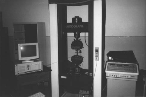
Experimental setup of tension-tension testing.
The specimens with the CNT thread were cut from the material plates according to the ASTM D3039-76 specification. The dimensions of the testing specimens were length×width=250 mm×25 mm. The two ends of each CNT thread were covered with silver paste; two cable connectors were added again with silver paste in order to attach the bridge circuit for the resistance measurement. The conventional fixture was used for fatigue testing.
Tension-tension fatigue tests were performed at frequencies of 5 Hz for fatigue stresses ranging from 55 to 620 MPa. The SEM micrograph (see Figure 8) shows typical fatigue cracks of a composite occurred under tension-tension loading, in which one can obviously see the crack damage zone. The crack seems to be somewhat blunt, beyond which only little damage is observed. The voids are localized beyond the crack and along the crack lips.

SEM micrograph of the interior of braided composites.
In the present study, only the location of the X and Y directions of the 3D composite is discussed. The average resistance value of the CNT thread measured before loading is 197.4 kΩ in a row and 196.1 kΩ in a column.
The electric resistance changes in rows of the specimen under static tension loading 0.05% are shown in Figure 9A and B. The electric resistance changes in columns of the specimen are shown in Figure 10.

The electric resistance changes of sensors in rows and columns.

Damage exists at columns 2, space=38, a=35.
The bridge circuit can measure the resistance of the CNT thread in rows and columns of the specimen in real time. In Figures 11 and 12, the distribution of resistance changes of the CNT thread in rows and columns using the bridge circuit is plotted. The reason of different electrical resistance values at different positions is that the position of stress for the CNT thread inside the material is different.

Resistance changes of the carbon nanotube thread in a row.

Resistance changes of the carbon nanotube thread in a column.
In Figure 11, one can see that the internal defects of the composite material are relatively concentrated. Figure 12 shows that abnormal data mutations are more dispersed. Moreover, in the process of loading, the longitudinal damage is sustained.
Based on Figures 11 and 12, it is demonstrated that the damage distribution and detection results using CNT thread sensors are consistent.
5 Conclusions
We propose a method for embedding a CNT thread as an internal sensor into a 3D braided composite material preform. The results show that the CNT thread has crack monitoring capability during dynamic loading and failure prediction before the damage occurs. This method can also be proposed for precise failure location prediction in 3D braided composites.
We present an algorithm which improves the accuracy of damage detection. The new method using standardizations shows the excellently high performance of estimations of damage size and locations.
As a result, it would be necessary to prove the practicality of an embedded SHM approach for 3D braided composite materials in SHM research, which will improve its reliability and may result in new and improved safety standards for inspections.
References
[1] Liu ZL, Liu LF, Yu JY. Text. Res. J. 2012, 82, 1870–1879.10.1177/0040517512438129Search in Google Scholar
[2] Kim KJ, Yu WR, Lee JS, Gao LM, Thostenson ET, Chou TW. Composites 2010, 41, 1531–1537.10.1016/j.compositesa.2010.06.016Search in Google Scholar
[3] Kang I, Schulz MJ, Kim JH, Shanov VD. Smart Mater. Struct. 2006, 15, 737–748.10.1088/0964-1726/15/3/009Search in Google Scholar
[4] Li CY, Chou TW. Compos. Sci. Technol. 2008, 68, 3373–3379.10.1016/j.compscitech.2008.09.025Search in Google Scholar
[5] Wang Q, Wu N. Smart Mater. Struct. 2012, 21, 013001.10.1088/0964-1726/21/1/013001Search in Google Scholar
[6] Muto N, Yanagida H, Nakatsuji T, Sugita M, Ohtsuka Y, Arai Y, Takada K. J. Ceram. Soc. Jpn. 1993, 101, 860–866.10.2109/jcersj.101.860Search in Google Scholar
[7] Seo DC, Lee JJ. Compos. Struct. 1999, 47, 525–530.10.1016/S0263-8223(00)00016-7Search in Google Scholar
[8] Akira T. Int. J. Aeronaut. Space Sci. 2010, 11, 155–166.10.5139/IJASS.2010.11.3.155Search in Google Scholar
[9] Schulte K, Baron C. Compos. Sci. Technol. 1989, 36, 63–76.10.1016/0266-3538(89)90016-XSearch in Google Scholar
[10] Yoshiyasu H, Akira T. J. Intell. Mater. Syst. Struct. 2007, 18, 253–263.10.1177/1045389X06065467Search in Google Scholar
[11] Shu Y, Yan JN, Li ZY. Drill. Fluid Completion Fluid 2008, 25, 17–19.Search in Google Scholar
[12] Yang J, Huang XL. J. Compos. Mater. Sept. 2009, 43, 2223–2238.10.1177/0021998309339219Search in Google Scholar
[13] Wu AS, Coppola AM, Sinnott M, Chou TW, Thostenson ET, Byun JH, Kim BS. Compos. Sci. Technol. 2012, 72, 1618–1626.10.1016/j.compscitech.2012.06.012Search in Google Scholar
[14] Gao L, Chou TW, Thostenson ET, Zhang ZG, Coulaud M. Carbon 2011, 49, 3382–3385.10.1016/j.carbon.2011.04.003Search in Google Scholar
[15] Pandey G, Wolters M, Thostenson ET, Heider D. Carbon 2012, 50, 3816–3825.10.1016/j.carbon.2012.04.008Search in Google Scholar
[16] De Villoria RG, Yamamoto N, Miravete A, Wardle B. Nanotechnology 2011, 22, 185502.10.1088/0957-4484/22/18/185502Search in Google Scholar PubMed
[17] Naghashpour A, Hoa SV. Struct. Health Monitor. 2015, 14, 35–45.10.1177/1475921714546063Search in Google Scholar
[18] Naghashpour A, Hoa SV. Compos. Sci. Technol. 2013, 78, 41–47.10.1016/j.compscitech.2013.01.017Search in Google Scholar
[19] Naghashpour A, Hoa SV. Nanotechnology 2014, 24, 455502.10.1088/0957-4484/24/45/455502Search in Google Scholar PubMed
[20] Song YS, Chung K, Kang TJ, Youn JR. Compos. Sci. Technol. 2004, 64, 1629–1636.10.1016/j.compscitech.2003.11.008Search in Google Scholar
[21] Zhao HB, Zhang YY, Bradford PD, Zhou Q, Jia QX. Nanotechnology 2010, 21, 305502.10.1088/0957-4484/21/30/305502Search in Google Scholar PubMed
[22] Akira T. J. Intell. Mater. Syst. Struct. 2008, 19, 291–298.10.1177/1045389X07084154Search in Google Scholar
©2017 Walter de Gruyter GmbH, Berlin/Boston
This article is distributed under the terms of the Creative Commons Attribution Non-Commercial License, which permits unrestricted non-commercial use, distribution, and reproduction in any medium, provided the original work is properly cited.
Articles in the same Issue
- Frontmatter
- Original articles
- Effects of multiwalled carbon nanotube mass fraction on microstructures and electrical resistivity of polycarbonate-based conductive composites
- Preparation and fluid drag reduction properties of superhydrophobic paper-based films comprising carbon nanotubes and fluoropolymers
- Studies on the structural, thermal, and dielectric properties of fabricated Nylon 6,9/CaCu3Ti4O12 nanocomposites
- Metal-matrix composite fabricated with gas tungsten arc melt injection and precoated with NiCrBSi alloy to increase the volume fraction of WC particles
- Construction of polypropylene composite multifilaments filled with sodium perborate trihydrate-treated jute microparticles
- Damage detection of three-dimensional braided composite materials using carbon nanotube thread
- An exact solution for improved metal-composite joints reinforced by FG inter-layers
- Effect of chemical treatment on thermal properties of bagasse fiber-reinforced epoxy composite
- The superior ductility of fine SiCp/Al2014 composites after extrusion
- Optical properties and photocatalytic activity of CdS-TiO2/graphite composite
- Effects of bottom ash and granulated blast furnace slag as fine aggregate on abrasion resistance of concrete
- Surface modification of diamond and its effect on the mechanical properties of diamond/epoxy composites
- Numerical simulation of strain rate effect on the inelastic behavior of metal matrix composites
- Electromechanical characterization of multilayer graphene-reinforced cellulose composite containing 1-ethyl-3-methylimidazolium diethylphosphonate ionic liquid
- The effect of hydroxyapatite reinforcement and preparation methods on the structure and mechanical properties of Mg-HA composites
- The effect of yttrium incorporation on the formation and properties of α-Al2O3 coatings