
Pressure assisted sintering of Al2O3–Y2O3 glass microspheres: sintering conditions, grain size, and mechanical properties of sintered ceramics
-
Anna Prnová

 ,
Jana Valúchová
,
Jana Valúchová

Abstract
Glass microspheres with yttria-alumina eutectic composition (76.8 mol% Al2O3 and 23.2 mol% Y2O3) were prepared by sol-gel Pechini method and flame synthesis with or without subsequent milling. Prepared amorphous powders were studied by X-ray powder diffraction (XRD), particle size analysis (PSA), scanning electron microscopy (SEM) and differential thermal analysis (DTA). Hot pressing (HP), rapid hot pressing (RHP) and spark plasma sintering (SPS) were used to sinter amorphous precursor powders at 1600 °C without holding time (0 min). The preparation process including milling step resulted in amorphous powders with narrower particle size distribution and smaller particle size. All applied pressure assisted sintering techniques resulted in dense bulk samples with fine grained microstructure consisting of irregular α-Al2O3 and Y3Al5O12 (YAG) grains. Milling was beneficial in terms of final microstructure refinement and mechanical properties of sintered materials. A material with the Vickers hardness of HV = (17.1 ± 0.3) GPa and indentation fracture resistance of (4.2 ± 0.2) MPa.m1/2 was prepared from the powder milled for 12 h.
Introduction
Oxide materials in the system Al2O3–Y3Al5O12 with eutectic microstructure are currently intensively investigated mainly due to their excellent mechanical properties, which are to a large extent influenced by their final microstructure. For example, Vickers hardness in the range from 10 to 19 GPa [1], [2], [3], [4], [5], [6], [7], fracture toughness KIC from 1.9 to 4.6 MPa.m1/2 [2], [3], [4, 6], and fracture strength from 0.7 to 1.9 GPa were reported [2]. Moreover, these materials have high chemical and thermal resistance (low oxidation at high temperatures). These properties result from the strong interfaces in eutectic systems and predetermine these materials for ultra-high temperature applications, such as gas turbine blades, aircraft engine components, space crafts and others [8], [9], [10]. Many materials prepared by various methods (traditional directional solidification, Bridgman method, micro pulling-down – µPD method, laser heated zone re-melting – LHFZ method, edge -defined film fed growth EFG method) have been described and examined [8], [9], [10], [11], [12], [13], [14], [15], [16]. Most of these methods allow preparation of only small pieces of materials. Hot press sintering (HP) combined with controlled crystallization of glassy powders in the system Al2O3–Y2O3 is a promising method for preparation of ceramic materials with very fine eutectic microstructure from two points of view. The first is a possibility to obtain bigger parts. The second one is a more economical preparation due to much lower temperatures required in the process.
In our previous work, we decided to take the advantage of a specific property of glass, i.e. the glass transition temperature: above this temperature glass can be solidified by viscous flow at significantly lower temperatures when compared with sintering of ceramic powders. Preparation of ceramic materials by sintering of glass microspheres in the system Al2O3–Y2O3 with satisfactory hardness (HV = 16.3 GPa) [17], but imperfect microstructure with numerous processing-related defects was described. In this case, the precursor powders for the flame synthesis of the glass microspheres were prepared by precipitation method: the prepared glass microspheres were of insufficient homogeneity, which resulted in a coarse-grained and irregular microstructure of the final product [17]. Improved chemical homogeneity and narrower particle size distribution of glass microspheres were achieved by using sol-gel Pechini method where high homogeneity of powder on atomic level was obtained [18, 19]. However, during sol-gel Pechini method residual carbon is incorporated into the structure of prepared precursor powder. During flame synthesis, carbon acts as the blowing agent, resulting in creation of hollow glass microspheres. The presence of such microspheres prevents complete densification during viscous flow sintering. Therefore, milling of prepared glass microspheres offers the possibility to reduce the number of pores in the final microstructure and to further improve their mechanical properties. Milling (and therefore decreasing the particle size of powder before sintering) could offer another advantage, i.e. promote heterogeneous nucleation and crystallization during synthesis. Formation of smaller particles – fragments – during milling, creates new crystallisation or nucleation centres which may result in finer final microstructure.
The impact of particle size on mechanical properties of HP sintered Al2O3/YAG ceramics was studied [20]. The eutectic precursor materials with different particle sizes (<4 µm, 4–10 µm, <25 µm), prepared by pulverizing Al2O3/YAG eutectic rods solidified by laser floating zone, were sintered at temperatures 1450–1650 °C. The dense eutectic ceramics – 99.1 % (for particle size 4–10 µm) and 99.5 % (for the particle size <4 µm and <25 µm) were obtained. After sintering at 1600 °C the eutectic microstructure with several obvious isolated pores distributed in the areas between eutectic colonies was obtained. When the temperature was raised up to 1650 °C, the pores were eliminated.
Mechanical properties of a material strongly depend on the microstructure. Only pore-free and fine-grained microstructure can provide homogenous properties over the whole bulk of the material. Therefore, the present work deals with the preparation of the ceramics with fine eutectic microstructure. Refinement of the final microstructure was achieved by two approaches: (1) shortening of the sintering time by sintering without isothermal dwell, and (2) the use of higher heating and cooling rate (100 °C/min), using SPS and rapid hot-press sintering techniques. Furthemore, the particle size of the used glass powder was reduced by milling and, subsequently, conventional hot-press sintering was applied. High energy milling was also used after preparation of precursors by sol-gel method with following flame synthesis to obtain powders with smaller particle size and narrower particle size distribution. The influence of both particle size distribution and sintering conditions (applied pressure, heating rate) on microstructure and properties of Al2O3–Y2O3 glass microspheres sintered under applied pressure was studied. The resulting precursor systems as well as sintered materials were characterised and mechanical properties as Vickers hardness HV and indentation fracture resistance were determined.
Experimental part
The glassy powders in the system Al2O3–Y2O3 with eutectic composition (76.8 mol% Al2O3 and 23.2 mol% Y2O3) were prepared by combination of three methods: sol-gel Pechini synthesis [18] and flame synthesis [17], with or without subsequent milling. The sample prepared without milling is denoted as O, the milled samples are denoted as M1–M4.
The 99.9 % Al(NO3)3. 9H2O (Sigma Aldrich, Germany) and 99.9 % Y2O3 (Treibacher Industry, Austria) were used as starting materials for the sol-gel Pechini synthesis. The detailed procedure is described in the work [19] and flow chart of the process is shown in Fig. 1. Flame synthesis is also described in our previous works [17, 19, 21] and a schematic drawing with detailed description of individual parts of the used equipment is shown in Fig. 2.
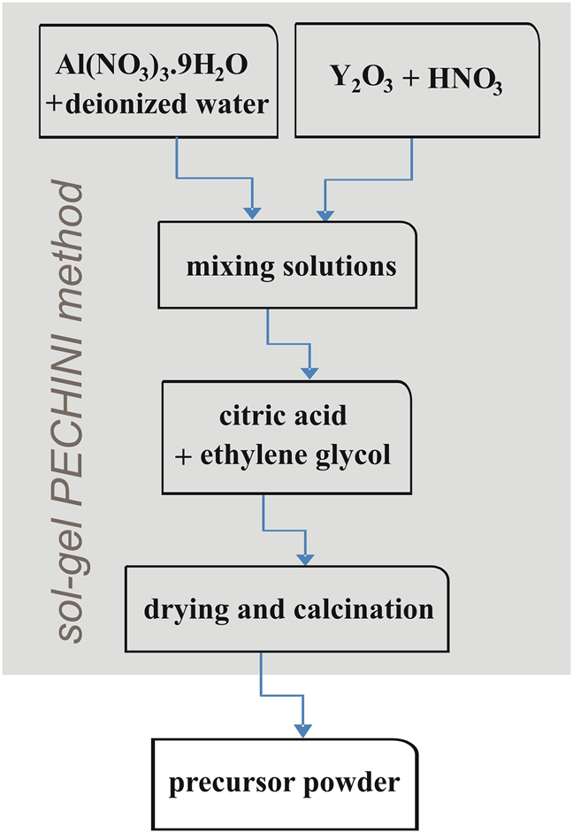
The schematic drawing of the sol-gel Pechini synthesis.
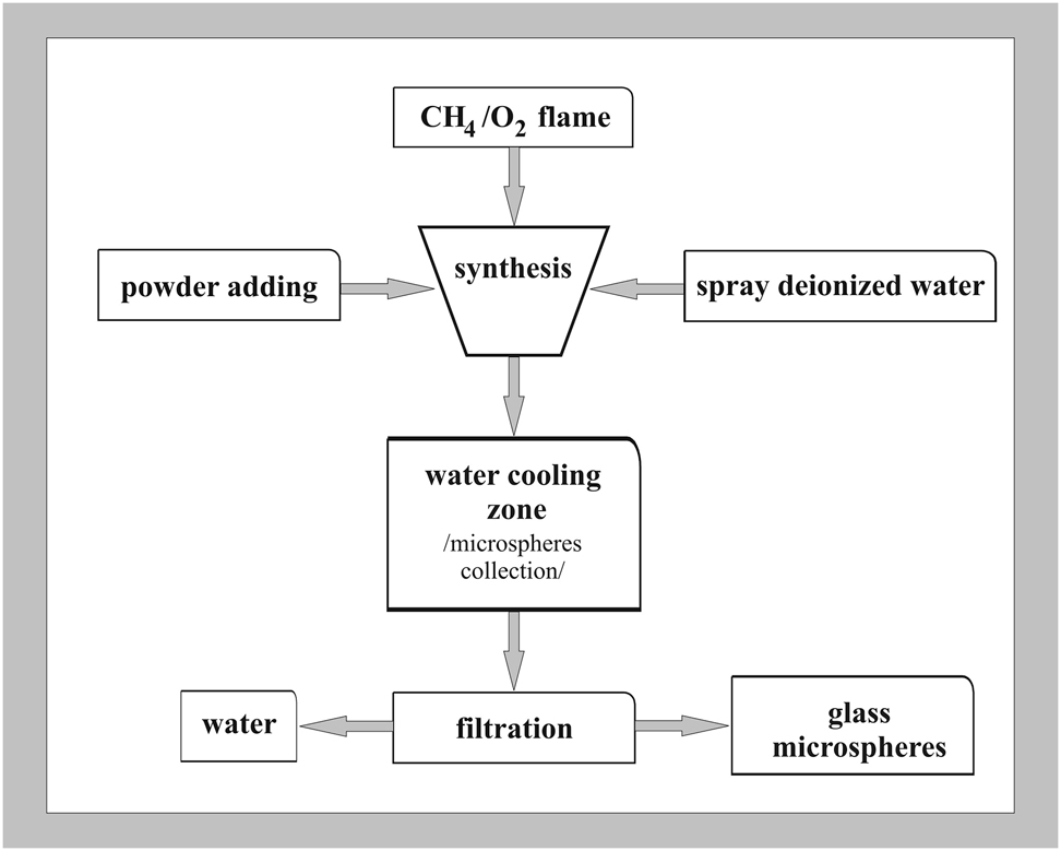
The schematic of preparation of glass microspheres by flame synthesis.
The vibratory micro mill Pulverisette 0 (Fritzsch GmbH, Germany) with agate bowl and one ball with the diameter of 5 cm was used for milling samples for different times (6, 9, 12 and 15 h). Grinding bowl oscillations were set to 3000 min−1, with 1 mm amplitude; the weight of the powder was 10 g.
X-ray powder diffraction analysis (Panalytical Empyrean, 45 kV accelerating voltage, CuKα radiation with λ = 1.5405 Å) was used to verify amorphous nature of prepared systems and for qualitative phase analysis of sintered bodies. Individual XRD patterns were recorded in 2Θ interval 10–80°. The measured data were analyzed using Rietveld refinement. Particle size analysis (Mastersizer 2000 Malvern Panalytical) were carried out to obtain information about particle size distribution of prepared systems. Thermal analysis (DTA/TG) was performed in nitrogen atmosphere in the temperature interval 35–1200 °C at a heating rate of 10 °C/min−1 using the Netzsch STA 449 F1 Jupiter analyser. DTA/TG records were evaluated by Netzsch Proteus 6.0.0 analysis software.
The morphology of glass microspheres and microstructure of hot-pressed specimens was examined by SEM (JEOL 7600F) at the accelerating voltage of 20 kV. Prior to the measurement the samples were embedded in a polymeric resin (Simplimet 1000, Buehler), carefully polished to prepare cross sections (Ecomet 300, Buehler) and then carbon sputtered to prevent charging. The grain size analysis of microstructure of sintered samples was obtained by the analysis of five different SEM images recorded in low-energy imaging (LEI) mode at a 5000× magnification, by measuring the size of at least 500 particles, using the software module NIS Elements Advanced Research for image analysis.
The prepared glassy powders were sintered by three different pressure-assisted sintering techniques: HP, RHP and SPS.
Laboratory hot-press Classic 0220 ZL was used for hot-press sintering experiments. Boron nitride coated graphite dies with the inner diameter of 12 mm were filled with prepared glass microspheres (∼1 g) and sintered under vacuum at 1600 °C with 0 min dwell time. The pressure of 30 or 40 MPa was applied. The final height of HP sintered samples was about 1.5 mm.
Rapid hot-pressing experiments were carried out using a DSP-507 rapid hot press (Dr. Fritsch GmBH, Germany). The prepared glass microspheres were poured into a graphite die (Ø 20 mm) lined with flexible graphite foil (0.5 mm thick) to prevent the direct contact between the sample and graphite die. The sintering was performed in vacuum without holding time at the constant temperature of 1600 °C. A constant heating rate of 100 °C/min with uniaxial pressure of 80 MPa was applied. Cooling rate was set to 70 °C/min. Sintering was performed under vacuum (5 Pa).
A Dr Sinter SPS-625 (Fuji Electronic Industrial CO., LTD.) was used for the SPS experiments. Carbon foil (0.2 mm thick) cladded graphite dies with inner diameter of 12 mm were filled with ∼1 g of prepared glass microspheres and sintered under vacuum (5–9 Pa). The samples were sintered at the heating rate of 100 °C/min to 1600 °C with 0 min dwell time. Cooling rate was 50 °C/min and the pressure applied during sintering was 80 MPa. The pulse patterns of the ON/OFF ratio were 12:2. The final height of SPS sintered samples was around 1.5 mm.
The densities of the prepared pellets were measured by the Archimedes method on OHAUS-type analytical balances at 25 °C in deionized water. The sintered bodies were dried before measurement (100 °C for 24 h). The resulting value was calculated as the mean of 10 measurements.
Vickers hardness (HV) and indentation fracture resistance measurements of polished samples were carried out using a Micro Hardness Tester, WIKI 200, at an indentation load force 9.8 N (1 kgf) using observation objective with 500× magnification and a high-resolution CCD camera with auto focus and auto reading function. The indentation dwell time was 10 s. The HV value was obtained from auto-measurement of indent size and hardness calculation. The indentation fracture resistance was calculated from the length of radial cracks created in the corners of imprints after indentation by the Anstis method [22]. The HV and indentation fracture resistance values for each sample were obtained as a mean from 10 measurements.
Results and discussion
Glass powder preparation and characterisation
The list of prepared glass powders is shown in Table 1. The sample O, original glass microspheres, was prepared by sol-gel Pechini method followed by flame synthesis.
The list of prepared precursor powders and PSA analysis results.
| Sample name | Milling time [h] | XRD | D(10) [µm] | D(50) [µm] | D(90) [µm] | SPAN | PSD |
|---|---|---|---|---|---|---|---|
| O | 0 | a | 8.129 | 19.844 | 39.410 | 1.576 | m |
| M1 | 6 | a | 2.940 | 9.701 | 24.572 | 2.230 | m |
| M2 | 9 | a | 2.505 | 8.660 | 22.904 | 2.356 | m |
| M3 | 12 | a | 2.337 | 8.605 | 22.841 | 2.383 | b |
| M4 | 15 | a | 2.056 | 7.944 | 21.733 | 2.477 | b |
-
a – amorphous, D(10), D(50), D(90) – parameters which inform that 10, 50 and 90 vol% of particles are smaller than the respective values, SPAN = (D90 – D10)/D50, PSD – particle size distribution (m – monomodal distribution of particle size, b – bimodal distribution of particle size), O – original glass microspheres, M – milled microspheres.
The samples M1–M4 were additionally milled for different times (6, 9, 12 and 15 h). These milling times selection was based of our previous work [22]. All prepared powders after flame synthesis were X-ray amorphous. For better explanation of changes in prepared samples, the main parameters D(10), D(50), D(90), and also SPAN parameters, calculated as SPAN = (D90 – D10)/D50, are listed in Table 1. The particle size distributions of individual samples are shown in Fig. 3. The samples M1 and M2 have fine monomodal particle size distribution with the SPAN values of 2.230 (sample M1) and 2.356 (sample M2). In samples O, M3 and M4 bimodal particle size distribution with the SPAN values of 1.576 (sample O), 2.383 (sample M3) and 2.477 (sample M4) was observed.
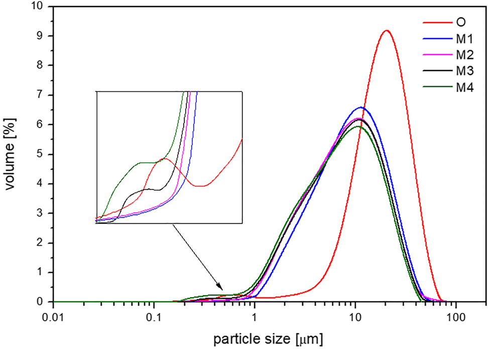
The influence of milling on particle size distribution of glass particles.
The particle size in prepared systems decreased sharply from D(90) = 39.410 µm in the case of sample O to D(90) = 21.733 µm for the sample M4. The highest values of D(10), D(50), and D(90) parameters, and the lowest value of SPAN were obtained in the sample O. Milling procedure has significant impact on the particle size and particle size distribution of prepared systems. The subsequent SEM examination of prepared samples revealed the presence of fully re-melted spherical particles in all samples. In case of the sample O, apart from solid glass microspheres, the presence of hollow microspheres was also observed (Fig. 4a, marked by arrows). Such microspheres can act as defects in microstructure of final material after sintering. In the milled samples, only fragments of such hollow microspheres were observed (Fig. 4b). The durability of solid glass microspheres was so high that they remained preserved in the powder after milling and were responsible for higher D(90) values.
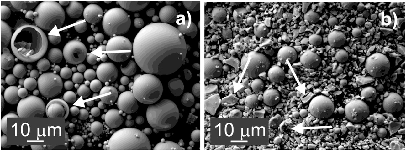
SEM micrographs of a) the sample O – the presence of hollow microspheres was observed (marked by arrows), b) sample M3 milled for 12 h milled – only fragments of the hollow microspheres were observed (marked by arrows).
Table 2 and Fig. 5 summarise the results of thermal analysis of the prepared systems. All measured curves contained two exothermic effect in the temperature intervals ∼936–958 °C and ∼997–1021 °C, respectively, which were attributed to a two-step crystallisation of yttrium-aluminium garnet (YAG) phase [23]. Only small differences in individual curves were observed.
The results of thermal analysis.
| Sample name | Tx1 [°C] | Tp1 [°C] | Te1 [°C] | Area 1. effect [µ vs. mg−1] | Tx2 [°C] | Tp2 [°C] | Te2 [°C] | Area 2. effect [µ vs. mg−1] |
|---|---|---|---|---|---|---|---|---|
| O | 937 | 942 | 953 | 34 | 1000 | 1007 | 1019 | 30 |
| M1 | 936 | 945 | 960 | 38 | 997 | 1009 | 1021 | 19 |
| M2 | 936 | 945 | 958 | 40 | 999 | 1010 | 1021 | 16 |
| M3 | 937 | 944 | 957 | 40 | 1000 | 1010 | 1021 | 16 |
| M4 | 936 | 943 | 958 | 40 | 998 | 1008 | 1021 | 14 |
-
Tx – onset of crystallisation temperature, Tp – maximum of peak temperature, Te – end of crystallisation temperature.
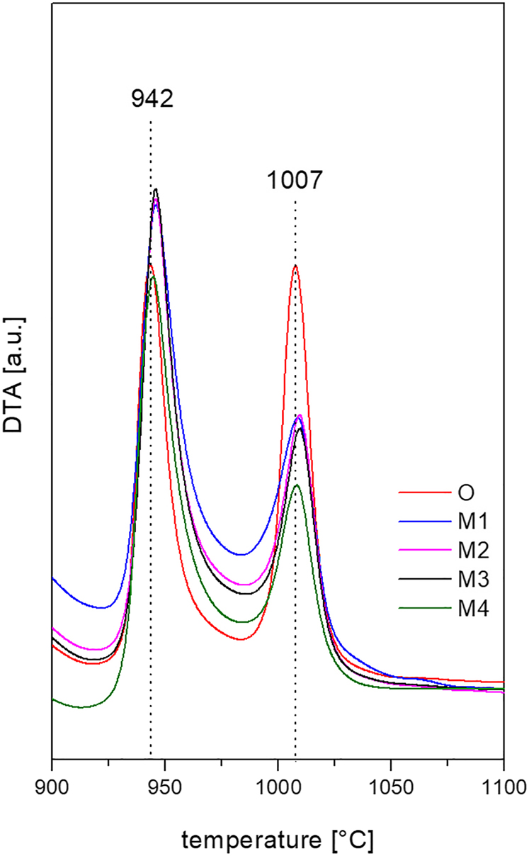
DTA of milled (M) and un-milled (O) precursors.
For sample O, the exothermic peaks were taller and slimmer, with approximately the same area, which indicated, that comparable amounts of the crystalline phase were created in both steps. The measured DTA curves of milled samples (M1-M4) contained two dissimilar peaks. The peaks were lower and broader, indicating slower crystallisation in comparison with the system O. Also, the first effects in the DTA curves of milled samples were more pronounced than the second ones, which could indicate a more pronounced formation of the YAG phase in the first temperature interval (∼936–958 °C).
Sintering of glass powders and ceramics materials characterisation
The list of prepared sintered samples and applied sintering conditions are shown in Table 3. As the extension of the time of sintering at high temperatures results in coarsening of the microstructure, all samples were sintered without isothermal dwell [17, 19, 21]. The maximum temperature of sintering 1600 °C was used in all cases. The heating rate 20 °C/min was used in the case of conventional HP experiments. The heating rate of 100 °C/min was applied in the case of RHP and SPS sintering experiments. Due to the very high heating rate and therefore short sintering time of RHP and SPS sintering the pressure of 80 MPa was applied so the samples could densify easily during the viscous flow densification period. However, it was found that increasing the heating rate from 20 to 100 °C/min impaired the density of the final material. HP sintered material achieved the relative density of 98.9 % while SPS and RHP sintered sample were only 96.8 and 97.2 % dense, respectively. The decrease in material compaction is both in SPS and RHP approximately at the same level: in can be therefore concluded that the influence of the heating method (resistive heating of the graphite die vs. pulse DC heating) on the compaction is negligible. Due to higher final density achieved by conventional hot pressing, only this technique was used for further experiments with milled samples with the heating rate of 20 °C/min.
The list of prepared samples sintered at 1600 °C without dwell time.
| Name of sintered sample | Sintering | Powder | Density [g.cm−3] | MC [%] | HV [GPa] | KIC [MPa.m1/2] | Rietveld refinement YAG:Al2O3 ratio [wt%] | |
|---|---|---|---|---|---|---|---|---|
| Method | Pressure [MPa] | |||||||
| S1 | HP | 30 | O | 4.35 ± 0.02 | 98.9 | 17.6 ± 0.7 | 3.8 ± 0.3 | 68.0:32.0 |
| S2 | RHP | 80 | O | 4.27 ± 0.01 | 97.2 | 15.4 ± 0.9 | 4.2 ± 0.3 | 68.3:31.7 |
| S3 | HP | 30 | M1 6 h | 4.36 ± 0.01 | 99.3 | 17.2 ± 0.4 | 3.8 ± 0.3 | 67.9:32.1 |
| S4 | HP | 30 | M2 9 h | 4.36 ± 0.03 | 99.4 | 17.3 ± 0.2 | 3.8 ± 0.2 | 68.4:31.6 |
| S5 | HP | 30 | M3 12 h | 4.35 ± 0.01 | 99.1 | 17.1 ± 0.3 | 4.2 ± 0.4 | 68.2:31.8 |
| S6 | HP | 30 | M4 15 h | 4.34 ± 0.02 | 98.7 | 15.8 ± 1.3 | 4.4 ± 0.5 | 68.2:31.8 |
| S7 | SPS | 80 | O | 4.25 ± 0.01 | 96.8 | 16.9 ± 0.4 | 3.5 ± 0.3 | 69.2:30.8 |
-
MC – material compaction.
Since the systems both with monomodal and bimodal PSD were used, three possible arrangements of particles in green bodies were considered. In the first arrangement Fig. 6a, the powder with high particle uniformity and monomodal distribution is needed. In the second one, Fig. 6b, powder with bimodal PSD is considered, when the small particles fill the cavities between the larger particles, thus minimizing the amount of pores in sintered materials. Based on the SEM analysis of milled samples, the model in Fig. 6c is characteristic for the systems prepared by milling in this work, in which small particles, formed by grinding, surround the large ones, reducing the amount of pores in sintered materials.
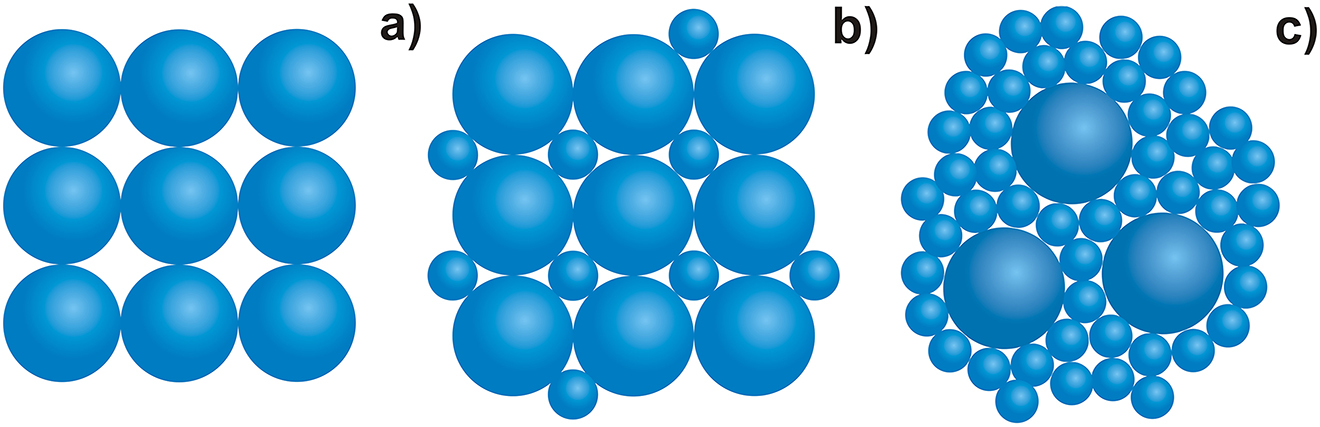
Suggested distribution of particles in sintered materials a) in monomodal particle size distribution; b) and c) in bimodal particle size distribution.
XRD analysis of powdered sintered pellets confirmed polycrystalline nature of all sintered samples and the presence of corundum – α-Al2O3 (COD 96-900-9672), yttrium aluminate garnet – Y3Al5O12 (COD 96-200-3067) and carbon (COD 96-901-2706) was observed, Fig. 7.
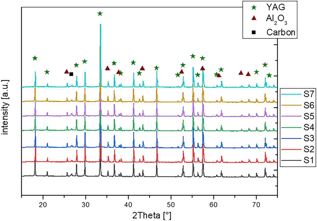
XRD patterns of sintered samples. Identified phases: YAG COD 96-200-3067; Al2O3 COD 96-900-9672; carbon COD 96-901-2706.
The presence of carbon is caused by sintering of samples in graphite die. The ratio between alumina and YAG defined by Rietveld refinement (Table 3) is almost identical in all samples. The use of different sintering technique does not influence the phase composition of sintered materials.
The density measurements revealed some differences among individual samples. In case of sample S2 (RHP of the powder O) and sample S7 (SPS of the powder O) the lowest densities 4.27 and 4.25 g.cm−3 were obtained. In other samples, the density values varied from 4.335 to 4.364 g.cm−3. The level of material compaction was calculated as a ratio of measured density and theoretical density of fully crystallised material (4.39 g.cm−3) [19]. The best results of sample compaction were obtained in samples sintered by conventional HP, using milled powders (experiments S3–S5). Satisfactory values of HV and indentation fracture resistance were achieved in all samples except of S2, S6 and S7. The best results were determined for samples S3–S5 (HV ∼ 17.1 ± 0.2 to 17.3 ± 0.2 GPa; fracture resistance ∼3.8 ± 0.4 to 4.2 ± 0.2 MPa.m1/2), Fig. 8.
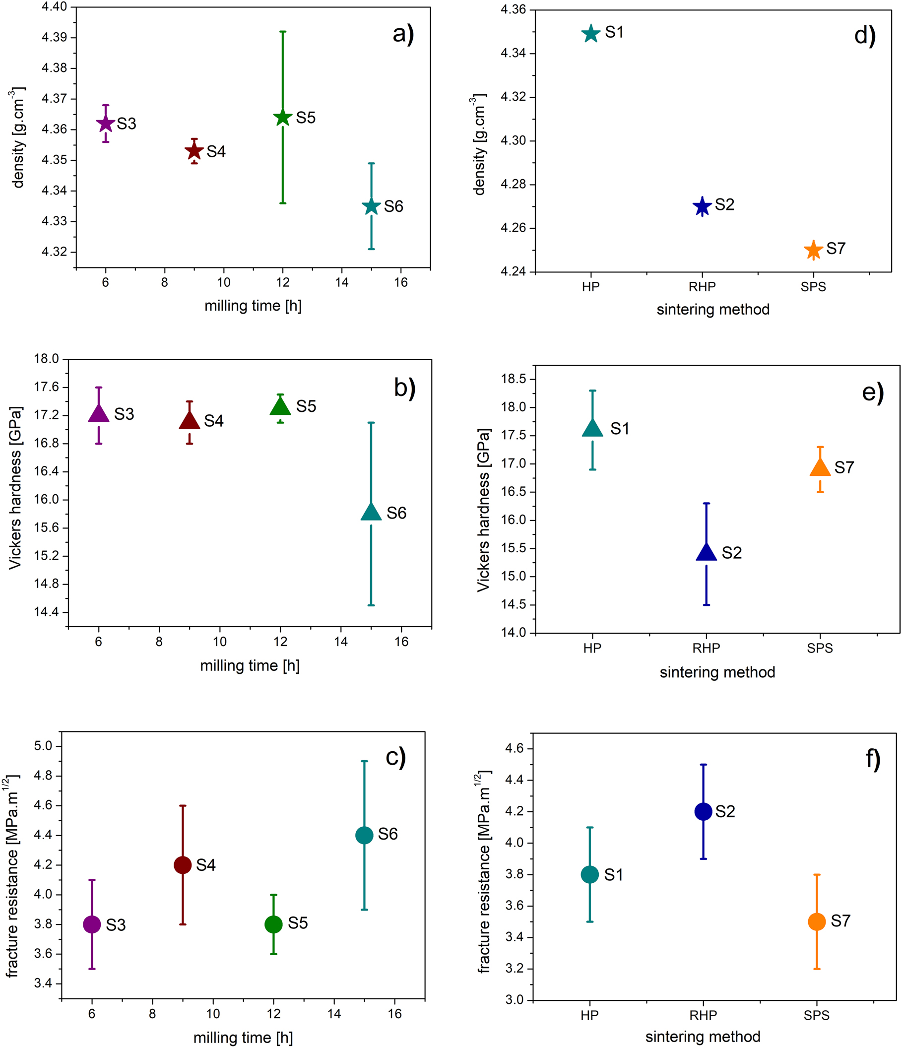
Physical properties of prepared materials (a) densities, (b) Vickers hardness and (c) indentation fracture resistance of samples prepared from milled powders, (d) densities, (e) Vickers hardness and (f) indentation fracture resistance of HP, RHP and SPS sintered O powders.
The values of the standard deviations of HV and indentation fracture resistance measurements of samples S3–S5, which range between 0.2 and 0.4 indicate homogeneous microstructure and homogeneous properties in the whole volume of prepared materials. This assumption was confirmed by SEM examination, which showed a homogeneous, almost defect-free microstructure of sintered materials S3–S5. The microstructure of all prepared materials consists of Al2O3 rich grains (dark areas) enclosed in YAG matrix (white grains) Fig. 9. A detailed SEM examination and subsequent grain size measurements revealed the presence of a fine microstructure with grain size in sub-micron region (∼90 % of grains had grain size lower than 0.7 µm) in sintered materials prepared from milled powders M2 and M3 (Fig. 9 samples S4 and S5). Although sample S6 has very fine microstructure, it contains inhomogeneities, defects, and pores, which impair mechanical properties. The presence of inhomogeneities, is also reflected in higher deviation of measured HV as and KIC values. However, the presence of such defects can inhibit and arrest the crack propagation in the material, so higher KIC values were achieved. These results confirm that the particle size and particle size distribution influence the final properties and microstructure of sintered materials. The obtained values are comparable with the results reported in our previous work, where the temperature of 1600 °C, pressure 30 MPa and the dwell time of 30 min were applied (HV = 16.3 ± 0.8 GPa, indentation fracture resistance = 5.5 ± 0.5 MPa.m1/2) [12]. The Vickers hardness values were higher, with smaller standard deviation, in the samples prepared from milled powders.
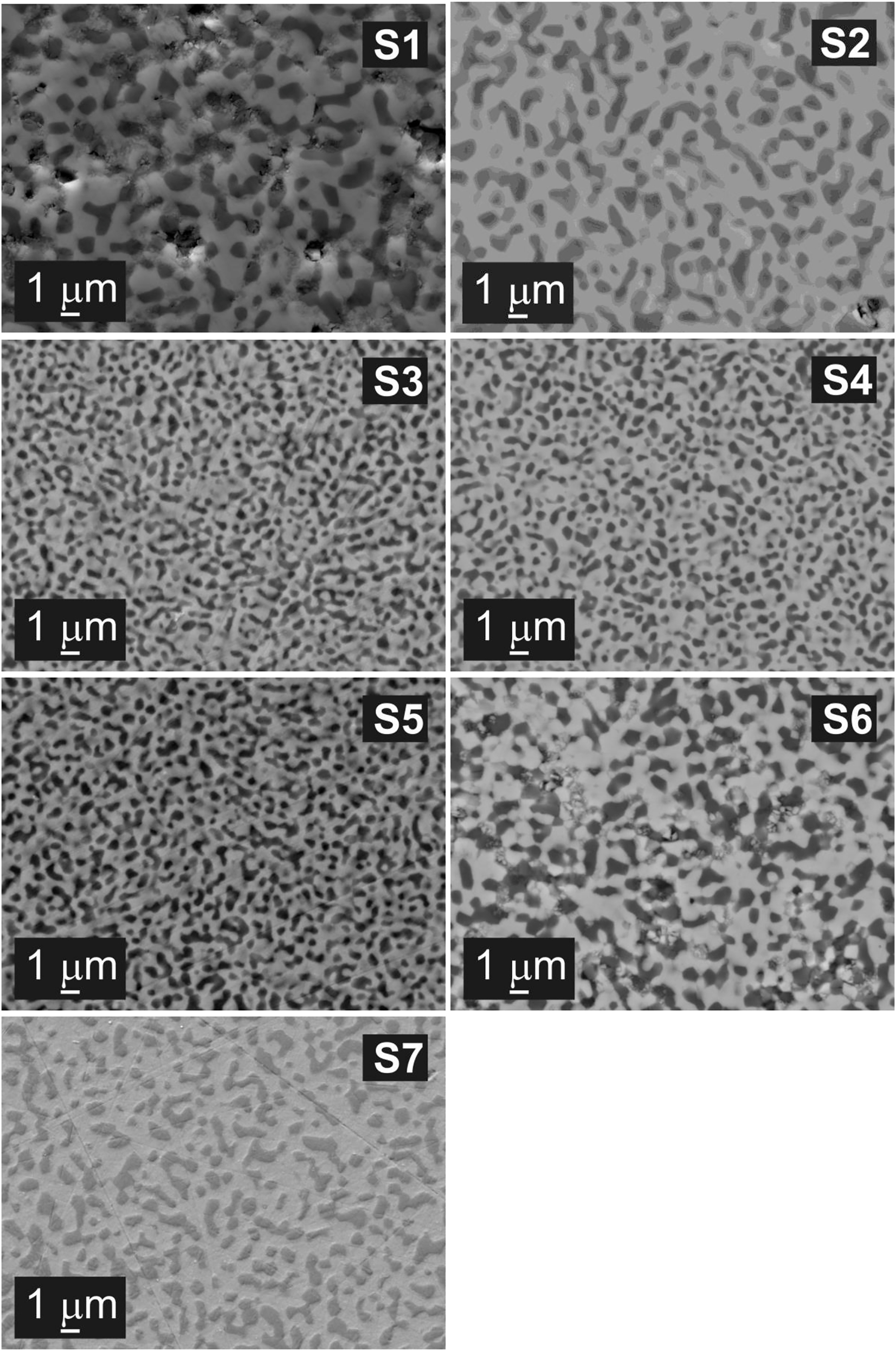
SEM microstructure of samples S1 - HP-O; S2 - RHP-O; S3 - HP-M1-6h; S4 - HP-M2-9h; S5 - HP-M3-12h; S6 - HP-M4-15h; S7 - SPS-O.
Despite significantly higher compaction pressure, rapid hot-pressing and spark plasma sintering led to lower values of measured mechanical properties and lower densities when compared to only original, un-milled powder. Although additional RHP and SPS experiments have to be carried out with milled powders to confirm the assumption, the already obtained results imply that using higher heating rates could have negative impact on the densification by viscous flow. Further optimization of precursor powder preparation is necessary for further improvement of mechanical properties and microstructure of sintered materials.
Conclusions
Five glassy powders of the same eutectic composition (76.8 mol% Al2O3 and 23.2 mol% Y2O3) were prepared by combination of sol-gel Pechini synthesis, flame synthesis and milling. HP, RHP and SPS were used for sintering of the powders at the temperature of 1600 °C, pressures 30 and 80 MPa, without holding time and with heating rates 20 and 100 °C/min. The density of prepared pellets ranged from 4.250 to 4.364 g.cm−3 which corresponds to the relative density between 96.8 and 99.4 %. The best mechanical properties HV = (17.1 ± 0.3) GPa, indentation fracture resistance (4.2 ± 0.2) MPa.m1/2 and finest eutectic microstructure with grain size in sub-micron range (∼90 % of grains have grain size lower than 0.7 µm) was obtained in the material prepared by HP of the powder milled for 12 h.
Article note:
A collection of invited papers based on presentations at the 14th International Conference on Solid State Chemistry (SSC 2021) held in Trencin, Slovakia, June 13–17, 2021.
Funding source: Agentúra na Podporu Výskumu a Vývoja
Award Identifier / Grant number: 17-0049, 19-0010
Funding source: Vedecká Grantová Agentúra MŠVVaŠ SR a SAV
Award Identifier / Grant number: 1/0527/18, 2/0026/17
Acknowledgment
This paper is a part of dissemination activities of project FunGlass. This project has received funding from the European Union’s Horizon 2020, research and innovation programme under grant agreement No 739566. The financial support of this work by the projects APVV-17-0049, APVV-19-0010, VEGA 2/0026/17 and VEGA 1/0527/18 is gratefully acknowledged. We also thank the support from the project Centre for Functional and Surface Functionalized Glass (CEGLASS), ITMS code is 313011R453, operational program Research and innovation, co-funded from European Regional Development Fund.
-
Research funding: This work was funded by Agentúra na Podporu Výskumu a Vývoja (17-0049, 19-0010) and Vedecká Grantová Agentúra MŠVVaŠ SR a SAV (1/0527/18, 2/0026/17).
References
[1] F. J. Paneto, J. L. Pereira, J. O. Lima, E. J. Jesus, L. A. Silva, E. Sousa Lima, R. F. Cabral, C. Santos. Int. J. Refract. Metals Hard Mater. 48, 365 (2015), https://doi.org/10.1016/j.ijrmhm.2014.09.010.Search in Google Scholar
[2] T. Isobe, M. Omori, S. Uchida, T. Sato, T. Hirai. Sci. Technol. Adv. Mater. 3, 239 (2002), https://doi.org/10.1016/S1468-6996(02)00021-9.Search in Google Scholar
[3] P. B. Oliete, M. J. López-Robledo, J. I. Peña, J. Silva. Ceram. Int. 43, 16270 (2017), https://doi.org/10.1016/j.ceramint.2017.08.212.Search in Google Scholar
[4] F. Niu, D. Wu, G. Ma, J. Wang, J. Zhuang, Z. Jin. Procedia CIRP 42, 91 (2016), https://doi.org/10.1016/j.procir.2016.02.196.Search in Google Scholar
[5] J. Z. Yu, J. Zhang, H. J. Su, K. Song, L. Liu, H. Z. Fu. J. Inorg. Mater. 27, 843 (2012), https://doi.org/10.3724/SP.J.1077.2012.11627.Search in Google Scholar
[6] H. Su, J. Zhang, Ch. Cui, L. Liu, H. Fu. Mater. Sci. Eng. A 479, 380 (2008), https://doi.org/10.1016/j.msea.2007.06.080.Search in Google Scholar
[7] Y. Murayama, S. Hanada, Y. Waku. Mater. Trans. 44, 1690 (2003).10.2320/matertrans.44.1690Search in Google Scholar
[8] D. Liu, Y. Gao, J. Liu, F. Liu, K. Li, H. Su, Y. Wang, L. An. Scripta Mater. 114, 108 (2016), https://doi.org/10.1016/j.scriptamat.2015.12.002.Search in Google Scholar
[9] A. Yoshikawa, K. Hasegawa, J. H. Lee, S. D. Durbin, B. M. Epelbaum, D. H. Yoon, T. Fukuda, Y. Waku. J. Cryst. Growth 218, 67 (2000), https://doi.org/10.1016/S0022-0248(00)00516-9.Search in Google Scholar
[10] K. Song, J. Zhang, L. Liu. Scripta Mater. 92, 39 (2014), https://doi.org/10.1016/j.scriptamat.2014.07.021.Search in Google Scholar
[11] C. Song, S. Wang, J. Liu, S. Zhai. Materials 11, 534 (2018), https://doi.org/10.3390/ma11040534.Search in Google Scholar
[12] K. Song, J. Zhang, X. J. Jia, H. J. Su, L. Liu, H. Z. Fu. J. Cryst. Growth 345, 51 (2012), https://doi.org/10.1016/j.jcrysgro.2012.02.017.Search in Google Scholar
[13] C. B. Finch, J. D. Holder, H. L. Yakel. J. Cryst. Growth 37, 245 (1977), https://doi.org/10.1016/0022-0248(77)90118-X.Search in Google Scholar
[14] J. H. Lee, A. Yoshikawa, S. D. Durbin, D. Ho Yoon, T. Fukuda, Y. Waku. J. Cryst. Growth 222, 791 (2001), https://doi.org/10.1016/s0022-0248(00)00998-2.Search in Google Scholar
[15] M. C. Mesa, S. Serrano-Zabaleta, P. B. Oliete, A. Larrea. J. Eur. Ceram. Soc. 34, 2071 (2014), https://doi.org/10.1016/j.jeurceramsoc.2013.11.011.Search in Google Scholar
[16] K. Yang, J. Rong, J. Feng, Y. Zhuang, S. Tao, C. Ding. J. Eur. Ceram. Soc. 36, 4261 (2016), https://doi.org/10.1016/j.jeurceramsoc.2016.06.012.Search in Google Scholar
[17] A. Prnová, D. Galusek, M. Hnatko, J. Kozánková, I. Vávra. Ceramics 55, 208 (2011).Search in Google Scholar
[18] M. P. Pechini. Method of preparing lead and alkaline-earth titanates and niobates and coating method using the same to form a capacitor. U. S. Pat. No. 3 330 697 (1967).Search in Google Scholar
[19] A. Prnová, J. Valúchová, M. Parchovianský, W. Wisniewski, P. Švančárek, R. Klement, Ľ. Hric, E. Bruneel, D. Galusek. J. Eur. Ceram. Soc. 40, 852 (2020), https://doi.org/10.1016/j.jeurceramsoc.2019.10.017.Search in Google Scholar
[20] B. Yao, H. Su, J. Zhang, Q. Ren, W. Ma, L. Liu, H. Fu. Mater. Des. 92, 213 (2016), https://doi.org/10.1016/j.matdes.2015.12.017.Search in Google Scholar
[21] A. Prnová, J. Valúchová, Ž. Dohnalová, O. Hanzel, R. Klement, E. Bruneel, D. Galusek. in FunGlass School 2019/Part 1 Book of Abstracts Čertov, pp. 41–42, Centre for Functional and Surface Functionalized Glass, Alexander Dubček University of Trenčín, Trenčín, Slovakia (2019).Search in Google Scholar
[22] G. R. Anstis, P. Chantikul, D. B. Marshall, B. R. Lawn. J. Am. Ceram. Soc. 64, 533 (1981), https://doi.org/10.1111/j.1151-2916.1981.tb10320.x.Search in Google Scholar
[23] A. Prnová, A. Plško, J. Valúchová, P. Švančárek, R. Klement, M. Michálková, D. Galusek. J. Therm. Anal. Calorim. 133, 227 (2018), https://doi.org/10.1007/s10973-017-6948-2.Search in Google Scholar
© 2021 IUPAC & De Gruyter. This work is licensed under a Creative Commons Attribution-NonCommercial-NoDerivatives 4.0 International License. For more information, please visit: http://creativecommons.org/licenses/by-nc-nd/4.0/
Articles in the same Issue
- Frontmatter
- Preface
- 14th Conference on Solid State Chemistry
- Conference papers
- Strong emission at 1000 nm from Pr3+/Yb3+-codoped multicomponent tellurite glass
- Pressure assisted sintering of Al2O3–Y2O3 glass microspheres: sintering conditions, grain size, and mechanical properties of sintered ceramics
- Present state of 3D printing from glass
- Raman spectra of MCl-Ga2S3-GeS2 (M = Na, K, Rb) glasses
- The chemistry of melting oxynitride phosphate glasses
- Structure and magnetic properties of Bi-doped calcium aluminosilicate glass microspheres
- Special Topic Paper
- Synthesis design using mass related metrics, environmental metrics, and health metrics