Dynamic propagation of an Airy beam in metasurface-enabled gradiently-aligned liquid crystals
-
Meini Gao
 ,
Wenfeng Cai
,
Wenfeng Cai
 and
Yan Jun Liu
and
Yan Jun Liu

Abstract
Due to the unique self-acceleration, self-healing, and non-diffraction properties, Airy beams have been explored extensively and found applications in various fields. It has been proven as an essential aspect to tune the trajectory of Airy beams for extensive applications. In this paper, we propose a method based on liquid crystal (LC) alignment with metasurfaces, which enables dynamic tuning of the trajectory of Airy beams. Benefiting from both the tunable property of LCs and the compact alignment of metasurfaces, we achieve a sizeable linear potential in a short distance, which leads to the effective tuning of the trajectory of Airy beams dynamically. The introduction of metasurfaces into the alignment of LCs provides a promising method to manipulate the planar optical field.
1 Introduction
Up to now, Airy beams have drawn intensive attention due to their unique properties of non-diffracting, self-healing, and self-accelerating along curved trajectories [1–23]. In recent decades, Airy beams have been widely used in plasma channels [5], particle manipulation [6, 7], atmospheric communication [8], laser-induced discharge [9], spatiotemporal photon bombs [10, 11], all-optical routing [12], and three-dimensional imaging [13–15]. Various methods have been developed to generate Airy beams, such as cubic phase masks [16, 17], designed optical metasurfaces [18, 19], asymmetric nonlinear photonic crystals [20], optical aberrations [21], and spatial light modulators (SLM) [22]. Of the most necessary is to tune the trajectory of Airy beams for broad applications. For example, the tunable trajectory offers an additional degree of freedom for atmospheric communication [8], all-optical routing [12], and 3D imaging [13–15]. Changing the generation parameters of the phase plate is a straightforward way to tune the trajectory [23, 24]. However, the change of the generation parameters will subsequently affect the other properties of Airy beams, such as the full-width at half-maximum (FWHM) of the main lobe. Another effective method is to manipulate the trajectory of Airy beams during their propagation, which is highly dependent on the medium properties. The propagation characteristics of Airy beams have been widely studied in various media, such as free space [2, 25, 26], nonlinear media [27, 28], inhomogeneous media [29, 30], chiral media [31], uniaxial crystals [32, 33], etc. A linear potential, which can be realized with the gradient refraction index (GRI) in the materials, has been proposed to effectively control the trajectory of Airy beams [34, 35]. Photorefractive crystals are a good candidate to achieve the GRI. Ye et al. [27] have demonstrated tunable Airy beams in strontium barium niobate (SBN) crystals, in which the GRI is formed by light irradiation with specially designed intensity distribution. However, only a small GRI (0.00045/mm) can be created in the photorefractive crystal at a very high driving voltage (4.2 kV/cm), which greatly limits practical applications. Therefore, it is highly desirable to find a new approach to dynamically control the trajectory of Airy beams.
For the GRI generation, liquid crystals (LCs) could be an ideal candidate, in which a significant refractive index modulation (0.2−0.3) can be achieved by controlling their alignment. Due to their large birefringence and versatile driving methods, LCs have been used in a wide range of applications, including Pancharatnam–Berry (PB) cubic phase masks [16, 17], smart windows [36], vector optical elements [37], metalens [38], metamaterial optical devices [39–43], biosensors [40], and lasers [44–46]. For LC-based devices, the alignment of LCs is a key factor that affects the performance of devices. Currently, mechanical rubbing and photoalignment are the prevailing methods for LC alignment. In contrast with mechanical rubbing, photoalignment is a noncontact alignment technique that eliminates the drawbacks of mechanical rubbing, such as surface damage, dust and electrostatic charge generation. It can be conveniently used to fabricate various optical elements with complex patterns, such as depolarizer [47], optical vortices generation [48], vector beams generation [49], polarized Airy masks [50], PB q-plates, and PB grating [51]. Moreover, using the photoalignment technique, one can create arbitrary patterns with a high resolution. For example, complex alignment patterns with a resolution of ∼1 μm have been demonstrated using a digital micro-mirror device (DMD) [47–50] or a laser direct-writing system [51, 52]. Even higher resolution can be achieved using laser interference [53, 54] and plasmonic photopatterning [55, 56]. However, the photoalignment technique is still limited by the stability issue and the highly demanded resolution (i.e., 1 μm). Recently, nanopatterns have been exploited for LC alignment in nanoscale resolution, such as atomic force-scribed nano grooves (120−300 nm) [57], lithographic metasurfaces (200−300 nm) [58], imprinted nanostructures (25 nm) [59], etc. More importantly, arbitrary nanopatterns with high-precision alignment capability can be fabricated, which is particularly favorable for the GRI generation.
This work proposes a method consisting of Au metasurfaces and nematic LCs, which can be used to achieve a linear potential to manipulate the trajectory of 1D Airy beams. Besides, the linear potential can be modulated with an external electric field resulting in the modulation of different trajectories. The tunable parabolic trajectory of Airy beams would stimulate novel applications, such as optical logical circuits, etc. Meanwhile, this work also provides a promising method for planar photonics [60, 61], which will trigger more exciting studies and applications.
2 Theory
As reported, the one-dimensional paraxial wave equation can be used to describe the propagation of Airy beams in LCs [3, 28]:
where
In Eq. (2), s = x/x0 represents a dimensionless transverse coordinate,
where δ n represents the GRI along the x-axis. Considering Eqs. (1)–(3), the acceleration g x of Airy beams in LCs can be deduced [28]:
where n is the refractive index of the medium. According to Eq. (4), the transverse acceleration of Airy beams in LCs is proportional to the GRI. As known, the effective refractive index of LCs neff is related to the alignment angle of LCs and can be described as:
where n o and n e are the ordinary and extraordinary refractive indices of nematic LCs, and θ is an angle between the director of LCs and the z-axis. The incident light propagates along the z-axis as well. Therefore, the GRI can be prepared with the gradient alignment of LCs, and subsequently used to tune the trajectory of Airy beams.
3 Materials and methods
3.1 Fabrication of LC samples
3.1.1 Nanofabrication of metasurfaces
The gold metasurface was fabricated on an ITO-coated glass substrate utilizing electron-beam lithography (EBL), followed by a metal evaporation and lift-off process. The ITO-coated glass substrate was cleaned with acetone and isopropyl alcohol (IPA) in an ultrasonic bath. To pattern the gold metasurface via EBL, a positive electron beam resist (AR-P 6200.09) was spin-coated on the ITO-coated glass substrate to form a resist layer with a thickness of 150 nm. It was prebaked at 150 °C for 2 min. To prevent the charge accumulation effect during subsequent electron beam exposure, a thin layer of conductive solution (AR-PC 5090.02) was spin-coated. EBL was carried out with a system (nB5, Nano beam). The current and voltage used were 4 nA and 80 kV, respectively. Each pattern exposed subfield was 20 × 20 μm2. The pattern development was done in AR 600–546 for 60 s. A 2 nm chrome adhesion layer and a 50-nm-thick gold film were subsequently deposited on the resist pattern, in an electron beam evaporation system (TF-500, HHV). The evaporation rate during the deposition process was controlled to be ∼0.4 Å s−1 with the vacuum level of 5 × 10⁻⁶ Torr inside the evaporator chamber. Finally, the gold metasurfaces were achieved after a lift-off process in the resist remover (AR 600–71).
3.1.2 Fabrication of the LC cell
Once the fabricated metasurfaces were ready, two pieces of glass substrates were mirror-symmetrically arranged in the upper and lower to assemble a LC cell. Alignment markers are used to align the two pieces of substrates under the microscope. The thickness of the LC cell was controlled to be 100 µm to facilitate the coupling of the free-space Airy beam. The substrates were assembled to form an LC cell with an optical adhesive NOA65 and then UV-cured for 5 min. Upon the LC cell ready, LCs (E7, n o = 1.52 and n e = 1.7032) were infiltrated at 70 °C by the capillarity force and then cooled down naturally.
3.2 The experimental setup
The cubic phase method is used to generate free-space Airy beams, as reported [2, 3, 66]. The experimental setup is schematically shown in Figure 1. The emitting light from the He–Ne laser at λ = 632.8 nm is impinging on the surface of the spatial light modulator (SLM, HOLOEYE Photonics AG, Germany) after spatial filtering, expanding (L1, H) and collimating (L2). The focal lengths of L1 and L2 are 4.51 mm and 200 mm. Before reaching SLM, a half-wave plate (λ/2) and a linear polarizer (P) are used to ensure the polarization direction of light parallel to the axis of LC alignment in SLM. The SLM-modulated light is reflected by the beam splitter (BS) towards the sample and CCD camera. A 4f system (L3: f = 250 mm, L4: f = 25 mm) and an objective lens (O1, 40×) are exploited to reduce the light beam size to nearly 100 μm and perform the Fourier transform. The generated Airy beam is then coupled into the LC layer along the direction indicated by the red arrow, as shown in the inset in Figure 1. In the direction perpendicular to the substrate, a CCD camera in combination with an objective (O2, 10×) is used to record the trajectory of the Airy beam’s propagation in the LC layer.

Schematic experimental setup for generation and recording the propagation trajectory of Airy beams. M: mirror, H: pinhole, L: lens, λ/2: λ/2 plate, P: polarizer, BS: beam splitter, SLM: spatial light modulator, O: objective lens, CCD: charge-coupled device, S: sample.
4 Results and discussion
4.1 Numerical simulation
As described theoretically, the one-dimensional paraxial wave equation can be used to describe the propagation of Airy beams in LCs. The gradient alignment of LCs can create the GRI, which can be further used to tune the trajectory of the finite energy Airy beam. The propagation trajectories of an Airy beam with and without the linear potential are depicted in Figure 2. The trajectory of the Airy beam in air is shown in Figure 2a. Correspondingly, the calculated acceleration of the Airy beam is 0.0203/mm. Figure 2b shows the acceleration of the Airy beam as a function of GRI, demonstrating that the acceleration increases with an increasing GRI in theory. The marking dots A and B in Figure 2b represent two cases in the LC cell with GRI of 0/mm and 0.2037/mm, respectively. Figure 2c and d illustrate the corresponding cases of the marking dots A and B. In Figure 2c, LC molecules are uniformly aligned with the director parallel to the z-axis (i.e., the propagation direction of the incident light). The calculated acceleration of the Airy beam is 0.0088/mm. While in Figure 2d, the director of LCs gradually changes from 0° to 80° along the x-axis, possessing GRI of 0.2037/mm. Correspondingly, the calculated acceleration of the Airy beam is 0.0714/mm. It is also noted that the FWHM (8.3 µm) of the main lobe keeps unaltered. The simulation parameter x0 = 5 µm for Airy beams is reasonably used for the observation in the following experiment.
![Figure 2:
The propagation trajectories of Airy beams in air (a) and in LCs (b–d) with the GRI. (b) The theoretically calculated acceleration of the Airy beam as a function of the GRI. The corresponding accelerations are 0.0203/mm (in air), 0.0088/mm [in LCs with GRI of 0/mm, corresponding to dot A in (b)], and 0.0714/mm [in LCs with GRI of 0.2037/mm, corresponding to dot B in (b)]. The scale factor x0 = 5 µm of Airy beams was used for calculation.](/document/doi/10.1515/nanoph-2023-0516/asset/graphic/j_nanoph-2023-0516_fig_002.jpg)
The propagation trajectories of Airy beams in air (a) and in LCs (b–d) with the GRI. (b) The theoretically calculated acceleration of the Airy beam as a function of the GRI. The corresponding accelerations are 0.0203/mm (in air), 0.0088/mm [in LCs with GRI of 0/mm, corresponding to dot A in (b)], and 0.0714/mm [in LCs with GRI of 0.2037/mm, corresponding to dot B in (b)]. The scale factor x0 = 5 µm of Airy beams was used for calculation.
4.2 Design and realization of the optical linear potential
As aforementioned, the GRI is an optical linear potential, which can be used to tune the trajectory of Airy beams. In this work, the GRI is generated by metasurface-aligned LCs. As reported [58], the LC molecules can be aligned by the gold-nanorod-based metasurface with their director along the long axis of the gold nanorods. Therefore, the effective index distribution of LCs can be achieved by programming the nanorod orientation of the metasurface. The designed gold-nanorod-based metasurfaces is on an indium-tin-oxide (ITO)-coated glass substrate, as shown in Figure 3a. The metasurfaces on both the upper and lower substrates are mirror-symmetrically arranged, ensuring to produce consistent alignment of the LC molecules from the top to the bottom across the LC cell, but gradually changed alignment along the x-axis to create the GRI. The metasurface structure has a period of P = 600 nm. Each gold nanorod has the length of L = 400 nm, the width of W = 100 nm, and the thickness of T = 50 nm. Moreover, we set 10 μm as a pixel, in which each gold nanorod has the same orientation. As shown in Figure 3a, the orientation angle of gold nanorods varies from 0° to 80° along the x-axis and keeps uniform along the z-axis, which ensures the index gradient 0.2037/mm of LCs (E7) along the x-axis. Upon the fabrication of metasurfaces, two pieces of glass substrates were carefully aligned with the help of aligning markers to assemble a LC cell and sealed with the UV-cured optical adhesive. Experimentally, the Airy beam will be coupled into the LC cell from the x–y plane and then propagate along the z-axis.
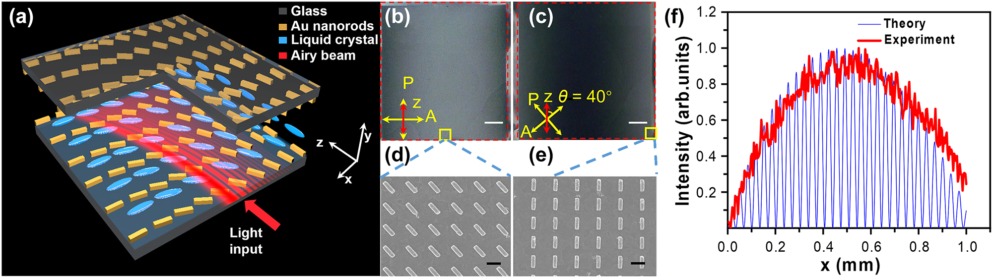
Design and characterization of the optical linear potential. (a) Schematic diagram of the LC cell with gradient LC alignment enabled by the metasurface. The red arrow indicates the propagation direction of the Airy beam. (b, c) POM images of the LC cell with the GRI under different polarization configurations, (b) θ = 0○ and (c) θ = 40○, where θ is the angle between the optical axis of polarizer P and the z-axis. (d, e) SEM images in the middle (d) and at the edge (e) of the fabricated metasurface labeled as yellow squares in (b & c). (f) Theoretically calculated (blue curve) and experimentally measured (red curve) transmission intensity distributions of the LC cell under the POM. P and A in (b & c) represent the optical axes of the polarizer and analyzer in the POM, respectively. Scale bar: 0.2 mm in (b & c) and 600 nm in (d & e).
To confirm the LCs’ alignment quality by the metasurface, the aligned LC cell was investigated under the polarizing optical microscope (POM), as shown in Figure 3b and c. It can be seen that the observed colors are quite uniform along the z-axis, indicating that the LCs have the same alignment; while the observed colors become gradually changed from bright in the middle to dark at the edge (see Figure 3b) or from dark in the middle to bright at the edge (see Figure 3c) along the x-axis, indicating that the LCs’ alignment angle has gradual change. Figure 3d and e shows the magnified SEM images of the fabricated gold metasurface at different positions labeled in Figure 3b and c. Furthermore, the optical intensity distribution along the x-axis under the POM was detected and compared with the theoretical intensity distribution calculated by the Eq. (6) [68], as shown in Figure 3f. α and β are the angles between the optical axis of the polarizer/analyzer and the fast axis of LCs, respectively. δ is the maximum phase difference between the ordinary and extraordinary light upon passing through the LC cell.
It is obvious that the experimental intensity distribution has a good agreement with the theoretical intensity distribution. As a result, we can conclude that LCs can be well aligned by the designed metasurface and a linear potential is therefore achieved.
4.3 Electric field characteristics
As known, when the LC cell is applied a voltage, the created electric field will re-align the LC molecules, hence changing the GRI inside the LC cell. Therefore, the aligned LC cell was investigated under different applied voltages of 0, 100, 200, and 250 Vpp, respectively, as shown in Figure 4. At V = 0 Vpp, there is an apparent gradient intensity inside the LC cell, as shown in Figure 4a. At V = 100 Vpp, the gradual alignment of LCs is completely destroyed, as shown in Figure 4b, indicating that the created GRI disappears at this state. As the voltage increases to 200 Vpp, most of LC molecules are aligned along the electric field direction, as shown in Figure 4c, in which the GRI distribution inside the cell can’t be described simply. At V = 250 Vpp, the POM image shows a completely dark view in Figure 4d, confirming that all the LC molecules can be re-aligned along the electric field direction. At this state, the coupled light will experience a uniform LCs with the refractive index of n o = 1.52 and the GRI of 0/mm.
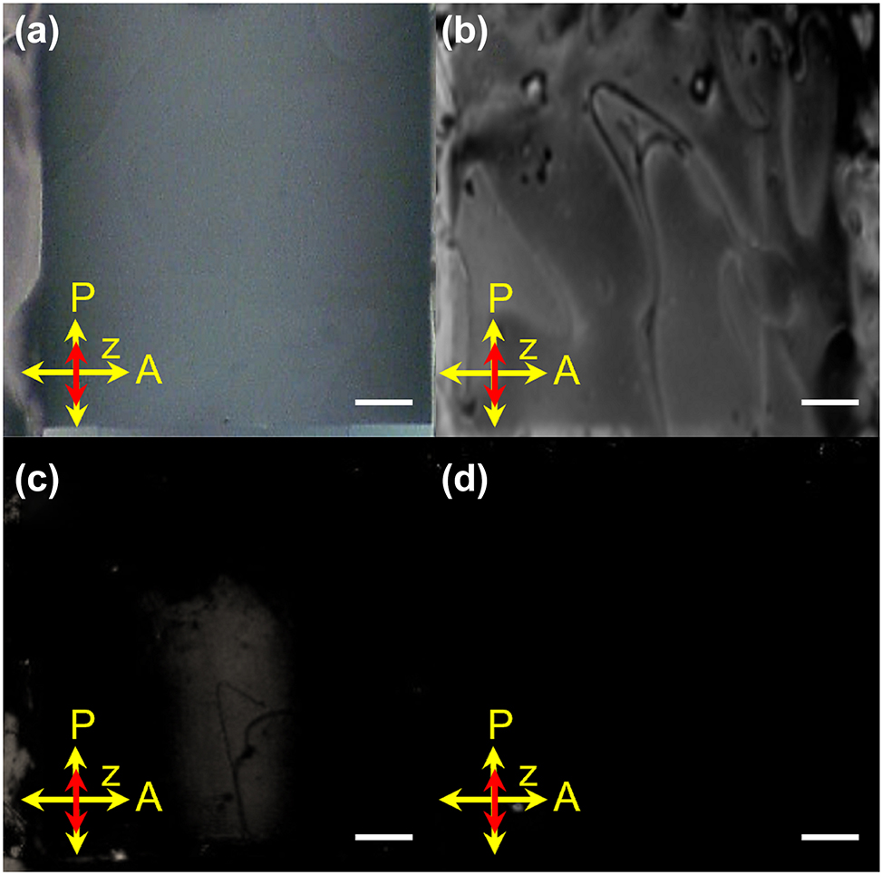
POM images of the LC cell with the applied voltages of (a) 0, (b) 100, (c) 200, and (d) 250 Vpp, respectively. Scale bar: 0.2 mm.
4.4 Dynamic propagation of Airy beams
With knowing the LC cell properties, we will then investigate the propagation and tuning properties of Airy beams inside the LC cell. The experimental setup in Figure 1 should be well calibrated. Firstly, a Gaussian beam was used to calibrate the experimental setup in our experiment. The trajectory of the Gaussian beam is provided in Figure 5a. The blue dotted line indicates the center of the beam. The fitting curve is shown in Figure 5b. The primary term coefficient is 7.5 × 10⁻⁵, which means the lateral displacement shall not exceed 1.5 nm after 2 mm propagating distance along the z-axis. Next, it is necessary to ensure that the experimentally generated Airy beam is consistent with the theoretical prediction. The trajectory of the Airy beam in air is fitted, as shown in Figure 5c. Figure 5d shows the propagation trajectory of the Airy beam in air. The blue dotted line indicates the center of the main lobe of the Airy beam. The main lobe and side lobe will alternate during propagation after the beam passes through the lens due to the Fourier transform. The trajectories A → B and B → C are not the same parabolas. It can be seen in Figure 5d, the trajectory from A → B point is the side lobe before the alternation of the main and the side lobe. Therefore, the main lobe was fitted for the trajectory between B and C point with the acceleration of 0.019/mm, which is very close to the theoretical value of 0.0203/mm given the experimental errors. After calibration, the theoretically designed Airy beams are generated for further investigation.
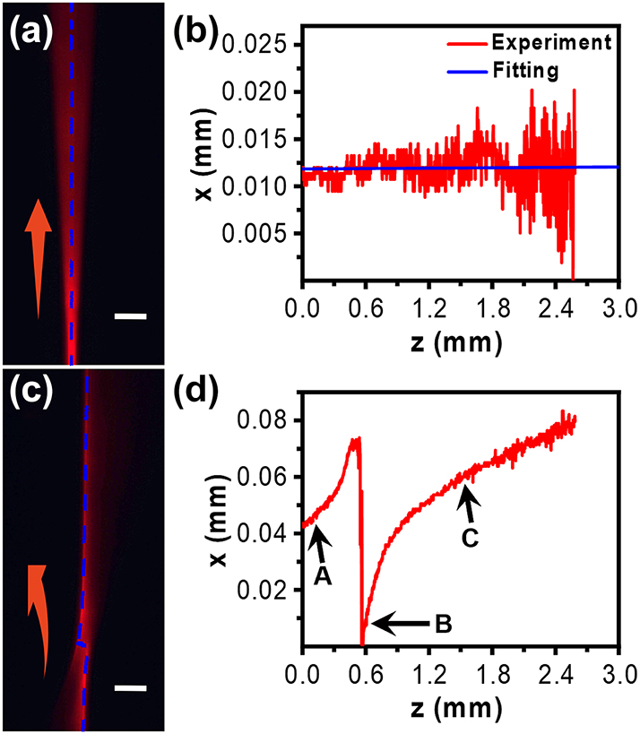
The CCD-recorded trajectories of the Gaussian beam (a) and Airy beam (c) in air. The blue dotted lines indicate the center and the main lobe of the light beams analyzed in (b) and (d), respectively. Red arrows indicate the beam propagation direction. Scale bar in (a & c): 0.3 mm.
The trajectory of Airy beams inside the LC cell can be recorded and characterized. Before characterizing the properties of the Airy beam in liquid crystals, one of the most important things is making sure that the Airy beam is achieved as designed. Therefore, the cross-section of the Airy beam in the x–y plane in air and the intensity profile along the x-axis are shown in Figure 6. Figure 6a shows the cross-section of the Airy beam in the x–y plane in air, which presents the typical Airy oscillation. Figure 6b shows the intensity profile along the x-axis with the FWHM of 6.3 µm, which corresponds to the yellow dashed line in Figure 6a. As a result, the free-space 1D Airy beam is successfully generated in our experiment.
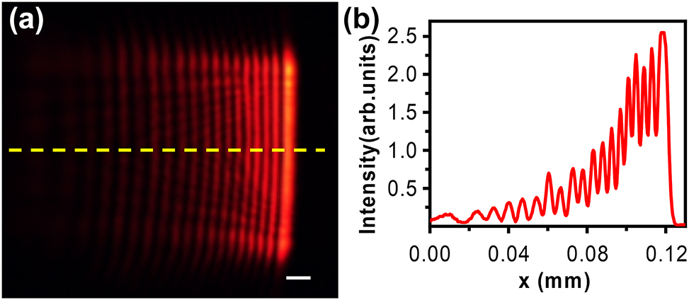
The field distribution in the x–y plane of Airy beams (a) and the intensity profile (b) along the line labeled in (a). Scale bar: 0.01 mm.
In our work, the distinct advantage is that the specially aligned LCs by the metasurface are used to tune the trajectory of Airy beams. Figure 7 depicts the effect of LCs on Airy beams. First, Airy beams propagating in air are presented in Figure 7a–c. Numerical fitting was carried out through the range between two dashed lines in Figure 7a. The experimentally achieved acceleration is 0.019/mm, which is in good agreement with the theoretical value of 0.0203/mm considering the experimental errors. The numerical fitting of main lobe and experimental results are in excellent agreement, as shown in Figure 7b. It was worth mentioning that in Figure 7a and b, only the beam trajectory between two dashed lines was considered due to the effective propagating distance of the Airy beam. As known, Airy beams are a type of diffraction-free beam for a limited propagation distance due to the apodization. The maximum propagating distance of being diffraction-free is determined by the generating parameters of the Airy beam [5]. The experimental parameters are set as: λ = 632.8 nm, φ = 20π, x0 = 0.005 mm. The effectively propagating distance can be deduced as below:
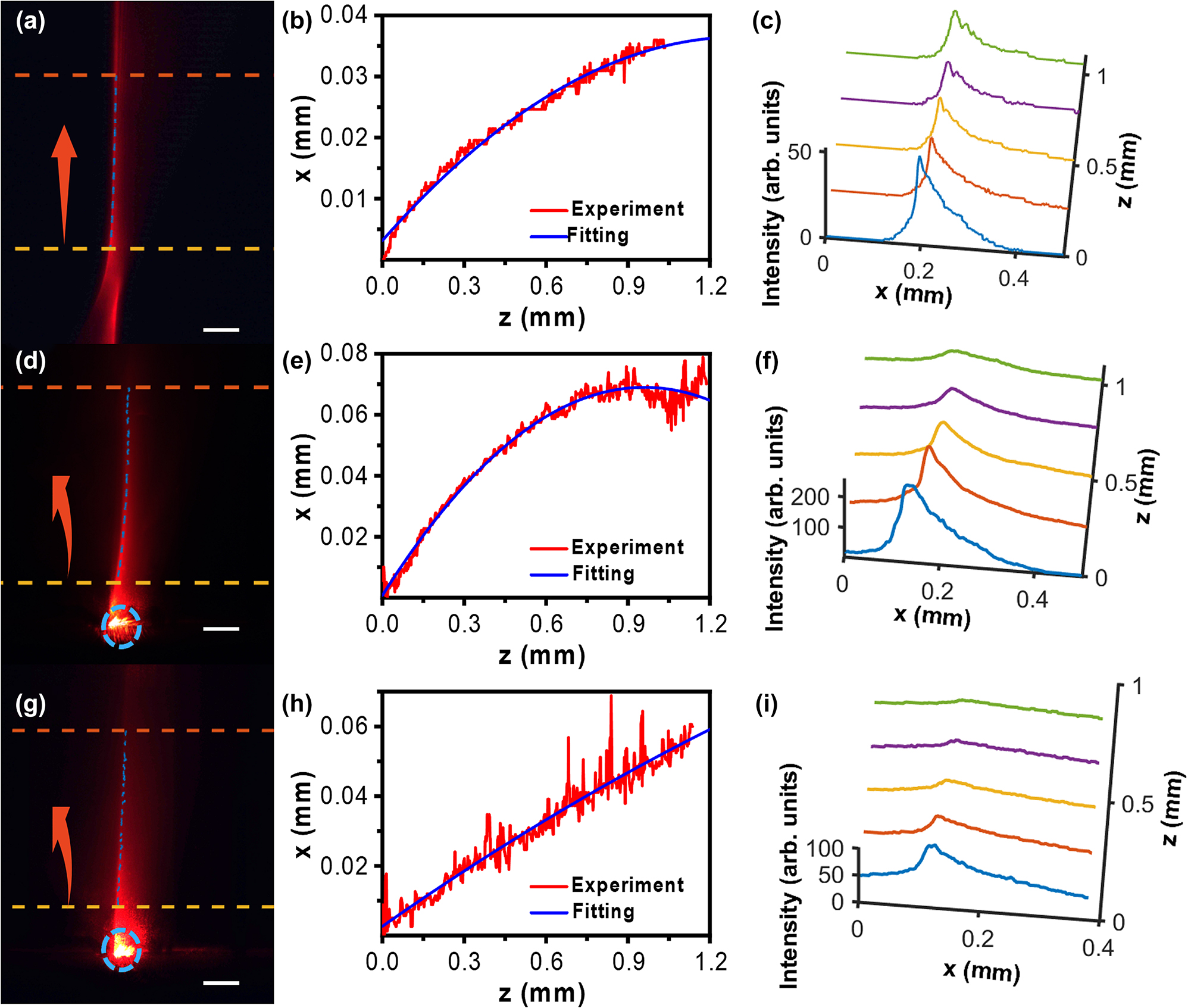
The propagation properties of Airy beams in air (a–c), and in LCs with GRI (d–f) and without GRI (g–i) including the images in x–z plane (a, d, g), the trajectory curves with both experimental measurement and numerical fitting (b, e, h), and cross-sectional intensity profiles at different propagation distances (c, f, i). The GRI inside the LC cell was 0.2037/mm. The GRI inside the LC cell is erased by applying a high enough voltage, resulting in the uniform ordinary index of LC (E7, n0 = 1.52) for the incident beam. Red arrows indicate the beam propagation direction. Blue circles label the starting point of beam coupling. Scale bar in (a, d, and g): 0.3 mm.
The calculated effective distance of the Airy beam is 1.1261 mm. In Figure 7a, the distance between two dashed lines is about 1 mm, in which the Airy beam propagates without apparent diffraction, as shown in Figure 7c.
The side lobes are not clearly observed in Figure 7a–c, which might be caused by the weak scattering and intensity of side lobes. The more important reason is that the scale bar in Figures 5 and 7 is thirty times larger than the one in Figure 6, indicating that the magnification is thirty times lower. However, we have to sacrifice the resolution to observe and analyze the overall trajectory. As a result, the Airy beams’ side lobes appear less distinct under the observation with a low magnification. In our experimental setup, the trajectory of the Airy beams is retrieved by collecting the scattering light from the top of the LC cell by the CCD camera. Due to the weak intensity of side lobes and the weak scattering, the recorded image by the CCD is not very clear. Therefore, only the main lobes are considered in our experiments.
Figure 7d–i shows the trajectories of the main lobe of the Airy beam in the LC layer with and without the applied voltage. Figure 7d–g presents the recorded images of the Airy beam in the LC cell without and with the applied voltage, respectively. In Figure 7d, the main lobe obviously curves towards the left due to the linear potential. As aforementioned, the designed LC alignment forms a linear potential (0.2037/m) in the LC cell. The fitting acceleration of the Airy beam is about 0.074/mm, which is in good agreement with the theoretical value of 0.0714/mm, as shown in Figure 7e.
As theoretically predicted, the trajectory of Airy beams will become flattened by decreasing the linear potential. In our experiment, the linear potential can be decreased by applying a voltage to the LC cell. Figure 7g shows the recorded trajectory of the Airy beam when applying the high voltage of 250 Vpp with the frequence of 1 kHz. The LC molecules will be completely re-aligned along the electric field direction, leading to a zero GRI. As a result, the LC cell can be considered as a uniform media with the ordinary refractive index (1.52 for LC E7). Figure 7h describes the fitting curve of the Airy beam under this condition. The measured acceleration from the fitting curve is 0.0065/mm, which is very close to the theoretical prediction (0.0088/mm). The discrepancy between the experiment and theory might be caused by the light scattering in the LC cell. The results of Figure 7d–g confirm the effective modulation of the Airy beams in the LC cell, providing a promising method for optical routing and computing. Noting that Figure 7a–g presents the propagation trajectories of Airy beams in uniform media with the refractive index of 1 and 1.52, respectively. Their corresponding fitting accelerations are 0.019/mm in air and 0.0065/mm in the LC layer. Therefore, we can also conclude that a larger index causes a decrease of the acceleration for Airy beams, which agrees well with the theoretical prediction.
5 Conclusions
In this work, we have demonstrated that the propagation trajectory of Airy beams can be electrically manipulated in a metasurfaces-aligned LC layer. A linear potential (i.e., GRI) has been successfully achieved in the LC cell with specially designed metasurfaces. The propagation trajectories of Airy beams in LC cells with and without the GRI have been explored experimentally. The results show that the GRI of LCs can tune the main lobe of Airy beams effectively. The acceleration can be modulated from 0.0088/mm to 0.0714/mm, and more, which dramatically exceeds the photorefractive crystal. Furthermore, the electrically tunable property of LCs enables the capability of dynamic Airy beams. Our proposed approach provides high precision, arbitrarily aligned LCs by specially designed metasurfaces, creating a unique platform for planar tunable photonic applications, for example 2D routers, 2D logic photonic circuits, etc.
Funding source: Development and Reform Commission of Shenzhen Municipality
Award Identifier / Grant number: XMHT20220114005
Award Identifier / Grant number: JCYJ20220818100413030
Funding source: Key Lab of Modern Optical Technologies of Education Ministry of China, Soochow University
Award Identifier / Grant number: KJS2132
Funding source: National Key Research and Development Program of China
Award Identifier / Grant number: 2022YFA1203702
Award Identifier / Grant number: 2017ZT07C071
Funding source: National Natural Science Foundation of China
Award Identifier / Grant number: 61975148
Award Identifier / Grant number: 62075093
Award Identifier / Grant number: 62211530039
Acknowledgments
The authors acknowledge the assistance of SUSTech Core Research Facilities.
-
Research funding: This work was supported in part by National Key R & D Program of China (Grant No. 2022YFA1203702), National Natural Science Foundation of China (Grant No. 61975148, 62075093, and 62211530039), Guangdong Innovative and Entrepreneurial Research Team Program (Grant No. 2017ZT07C071), Shenzhen Science and Technology Innovation Commission (Grant No. JCYJ20220818100413030), and Shenzhen Development and Reform Commission (Grant No. XMHT20220114005). This study was also funded by the Key Lab of Modern Optical Technologies of Education Ministry of China, Soochow University (Grant No. KJS2132).
-
Author contributions: All authors have accepted responsibility for the entire content of this manuscript and approved its submission.
-
Conflict of interest: Authors state no conflicts of interest.
-
Informed consent: Informed consent was obtained from all individuals included in this study.
-
Ethical approval: The conducted research is not related to either human or animals use.
-
Data availability: Data sharing is not applicable to this article as no datasets were generated or analysed during the current study.
References
[1] M. V. Berry and N. L. Balazs, “Nonspreading wave packets,” Am. J. Phys., vol. 47, no. 3, pp. 264–267, 1979. https://doi.org/10.1119/1.11855.Search in Google Scholar
[2] G. A. Siviloglou, J. Broky, A. Dogariu, and D. N. Christodoulides, “Observation of accelerating Airy beams,” Phys. Rev. Lett., vol. 99, no. 221, p. 213901, 2007. https://doi.org/10.1103/PhysRevLett.99.213901.Search in Google Scholar PubMed
[3] G. A. Siviloglou and D. N. Christodoulides, “Accelerating finite energy Airy beams,” Opt. Lett., vol. 32, no. 8, pp. 979–981, 2007. https://doi.org/10.1364/OL.32.000979.Search in Google Scholar
[4] J. Broky, G. A. Siviloglou, A. Dogariu, and D. N. Christodoulides, “Self-healing properties of optical Airy beams,” Opt. Express, vol. 16, no. 17, pp. 12880–12891, 2008. https://doi.org/10.1364/OE.16.012880.Search in Google Scholar PubMed
[5] P. Polynkin, M. Kolesik, J. V. Moloney, G. A. Siviloglou, and D. N. Christodoulides, “Curved plasma channel generation using ultraintense Airy beams,” Science, vol. 324, no. 5924, pp. 229–232, 2009. https://doi.org/10.1126/science.1169544.Search in Google Scholar PubMed
[6] J. Baumgartl, M. Mazilu, and K. Dholakia, “Optically mediated particle clearing using Airy wavepackets,” Nat. Photon., vol. 2, pp. 675–678, 2008. https://doi.org/10.1038/nphoton.2008.201.Search in Google Scholar
[7] C. Y. Chen, H. M. Yang, M. Kavehrad, and Z. Zhou, “Propagation of radial Airy array beams through atmospheric turbulence,” Opt. Laser. Eng., vol. 52, pp. 106–114, 2014. https://doi.org/10.1016/j.optlaseng.2013.07.003.Search in Google Scholar
[8] X. Z. Wang, Q. Li, W. Zhong, and Q. Wang, “Simulation of Airy beam drift in turbulence using a liquid crystal spatial light modulator,” Chin. J. Lasers, vol. 40, no. 12, p. 1213001, 2013.10.3788/CJL201340.1213001Search in Google Scholar
[9] M. Clerici, Y. Hu, P. Lassonde, et al.., “Laser-assisted guiding of electric discharges around objects,” Sci. Adv., vol. 1, no. 5, p. e1400111, 2015. https://doi.org/10.1126/sciadv.1400111.Search in Google Scholar PubMed PubMed Central
[10] V. Sophie, F. Kyle, K. P. Thompson, M. A. Alonso, and J. P. Rolland, “Airy beams: a geometric optics perspective,” J. Opt. Soc. Am. A, vol. 27, no. 12, p. 25742582, 2010. https://doi.org/10.1364/JOSAA.27.002574.Search in Google Scholar PubMed
[11] D. Abdollahpour, S. Suntsov, D. G. Papazoglou, and S. Tzortzakis, “Spatiotemporal Airy light bullets in the linear and nonlinear regimes,” Phys. Rev. Lett., vol. 105, no. 25, p. 253901, 2010. https://doi.org/10.1103/PhysRevLett.105.253901.Search in Google Scholar PubMed
[12] P. Rose, F. Diebel, M. Boguslawski, and C. Denz, “Airy beam induced optical routing,” Appl. Phys. Lett., vol. 102, no. 10, p. 101101, 2013. https://doi.org/10.1063/1.4793668.Search in Google Scholar
[13] Y. Guo, Y. R. Huang, J. Li, et al.., “Deep penetration microscopic imaging with non-diffracting Airy beams,” Membranes, vol. 11, no. 6, p. 391, 2021. https://doi.org/10.3390/membranes11060391.Search in Google Scholar PubMed PubMed Central
[14] T. Vettenburg, H. I. Dalgarno, J. Nylk, et al.., “Light-sheet microscopy using an Airy beam,” Nat. Methods, vol. 11, no. 5, pp. 541–554, 2014. https://doi.org/10.1038/nmeth.2922.Search in Google Scholar PubMed
[15] X. J. Tan, C. Kong, Y. X. Ren, C. S. W. Lai, K. K. Tsia, and K. K. Y. Wong, “Volumetric two-photon microscopy with a non-diffracting Airy beam,” Opt. Lett., vol. 44, no. 2, pp. 391–394, 2019. https://doi.org/10.1364/OL.44.000391.Search in Google Scholar PubMed
[16] H. T. Dai, X. W. Sun, D. Luo, and Y. J. Liu, “Airy beams generated by a binary phase element made of polymer-dispersed liquid crystals,” Opt. Express, vol. 17, no. 22, pp. 19365–19370, 2009. https://doi.org/10.1364/OE.17.019365.Search in Google Scholar PubMed
[17] B. Y. Wei, P. Chen, W. Hu, et al.., “Polarization-controllable Airy beams generated via a photoaligned director-variant liquid crystal mask,” Sci. Rep., vol. 5, no. 1, p. 17484, 2015. https://doi.org/10.1038/srep17484.Search in Google Scholar PubMed PubMed Central
[18] J. Wen, L. Chen, B. B. Yu, et al.., “All-dielectric synthetic-phase metasurfaces generating practical Airy beams,” ACS Nano, vol. 15, no. 1, pp. 1030–1038, 2021. https://doi.org/10.1021/acsnano.0c07770.Search in Google Scholar PubMed
[19] W. M. Hao, J. Wang, and L. Chen, “Compact broadband silicon-integrated Airy beam emitter,” Opt. Lett., vol. 46, no. 17, pp. 4084–4087, 2021. https://doi.org/10.1364/OL.433672.Search in Google Scholar PubMed
[20] T. Ellenbogen, N. V. Bloch, A. G. Padowicz, and A. Arie, “Nonlinear generation and manipulation of Airy beams,” Nat. Photon., vol. 3, pp. 395–398, 2009. https://doi.org/10.1038/NPHOTON.2009.95.Search in Google Scholar
[21] I. Dolev, T. Ellenbogen, N. V. Bloch, and A. Arie, “Control of free space propagation of Airy beams generated by quadratic nonlinear photonic crystals,” Appl. Phys. Lett., vol. 95, p. 201112, 2009. https://doi.org/10.1063/1.3266066.Search in Google Scholar
[22] D. G. Papazoglou, S. Suntsov, D. Abdollahpour, and S. Tzortzakis, “Tunable intense Airy beams and tailored femtosecond laser filaments,” Phys. Rev. A, vol. 81, no. 6, p. 061807, 2010. https://doi.org/10.1103/PhysRevA.81.061807.Search in Google Scholar
[23] L. Froehly, F. Courvoisier, A. Mathis, et al.., “Arbitrary accelerating micron-scale caustic beams in two and three dimensions,” Opt. Express, vol. 19, no. 17, pp. 16455–16465, 2011. https://doi.org/10.1364/OE.19.016455.Search in Google Scholar PubMed
[24] E. Greenfield, M. Segev, W. Walasik, and O. Raz, “Accelerating light beams along arbitrary convex trajectories,” Phys. Rev. Lett., vol. 106, no. 21, p. 213902, 2011. https://doi.org/10.1103/PhysRevLett.106.213902.Search in Google Scholar PubMed
[25] Y. Hu, P. Zhang, C. Lou, S. Huang, J. J. Xu, and Z. G. Chen, “Optimal control of the ballistic motion of Airy beams,” Opt. Lett., vol. 35, no. 13, pp. 2260–2262, 2010. https://doi.org/10.1364/OL.35.002260.Search in Google Scholar PubMed
[26] H. T. Dai, Y. J. Liu, D. Luo, and X. W. Sun, “Propagation dynamics of an optical vortex imposed on an Airy beam,” Opt. Lett., vol. 35, no. 23, pp. 4075–4407, 2010. https://doi.org/10.1364/OL.35.004075.Search in Google Scholar PubMed
[27] Z. Y. Ye, S. Liu, C. Lou, et al.., “Acceleration control of Airy beams with optically induced refractive-index gradient,” Opt. Lett., vol. 36, no. 16, pp. 3230–3323, 2011. https://doi.org/10.1364/OL.36.003230.Search in Google Scholar PubMed
[28] G. Q. Zhou, R. P. Chen, and G. Y. Ru, “Propagation of an Airy beam in a strongly nonlocal nonlinear media,” Laser Phys. Lett., vol. 11, no. 10, p. 105001, 2014. https://doi.org/10.1088/1612-2011/11/10/105001.Search in Google Scholar
[29] A. V. Zhukov, R. Bouffanais, M. B. Belonenko, and I. S. Dyuzhilov, “Three-dimensional ultrashort optical Airy beams in an inhomogeneous medium with carbon nanotubes,” Phys. Lett. A, vol. 381, no. 10, pp. 931–934, 2017. https://doi.org/10.1016/j.physleta.2017.01.008.Search in Google Scholar
[30] S. C. Cerda, U. Ruiz, V. Arrizon, and H. M. M. Cessa, “Generation of Airy solitary-like wave beams by acceleration control in inhomogeneous media,” Opt. Express, vol. 19, no. 17, pp. 16448–16454, 2011. https://doi.org/10.1364/OE.19.016448.Search in Google Scholar PubMed
[31] F. Zhuang, X. Y. Du, Y. Q. Ye, and D. M. Zhao, “Evolution of Airy beams in a chiral medium,” Opt. Lett., vol. 37, no. 11, pp. 1871–1873, 2012. https://doi.org/10.1364/OL.37.001871.Search in Google Scholar PubMed
[32] G. Q. Zhou, R. P. Chen, and X. X. Chu, “Propagation of Airy beams in uniaxial crystals orthogonal to the optical axis,” Opt. Express, vol. 20, no. 3, pp. 2196–2205, 2012. https://doi.org/10.1364/OE.20.002196.Search in Google Scholar PubMed
[33] H. H. Li, J. G. Wang, M. M. Tang, and X. Z. Li, “Propagation of the Airy beam along the optical axis of a uniaxial medium,” J. Mod. Opt., vol. 64, no. 21, pp. 2363–2369, 2017. https://doi.org/10.1080/09500340.2017.1360957.Search in Google Scholar
[34] W. Liu, D. N. Neshev, I. V. Shadrivov, et al.., “Plasmonic Airy beam manipulation in linear optical potentials,” Opt. Lett., vol. 36, no. 7, pp. 1164–1166, 2011. https://doi.org/10.1364/OL.36.001164.Search in Google Scholar PubMed
[35] N. K. Efremidis, “Airy trajectory engineering in dynamic linear index potentials,” Opt. Lett., vol. 36, no. 15, pp. 3006–3008, 2011. https://doi.org/10.1364/OL.36.003006.Search in Google Scholar PubMed
[36] C. Meng, E. G. Chen, L. P. Wang, et al.., “Color-switchable liquid crystal smart window with multi-layered light guiding structures,” Opt. Express, vol. 27, no. 9, pp. 13098–13107, 2019. https://doi.org/10.1364/OE.27.013098.Search in Google Scholar PubMed
[37] R. Wang, S. S. He, S. Z. Chen, et al.., “Electrically driven generation of arbitrary vector vortex beams on the hybrid-order Poincaré sphere,” Opt. Lett., vol. 43, no. 15, pp. 3570–3573, 2018. https://doi.org/10.1364/OL.43.003570.Search in Google Scholar PubMed
[38] S. H. Zhou, Z. X. Shen, X. Li, S. J. Ge, Y. Q. Lu, and W. Hu, “Liquid crystal integrated metalens with dynamic focusing property,” Opt. Lett., vol. 45, no. 15, pp. 4324–4327, 2020. https://doi.org/10.1364/OL.398601.Search in Google Scholar PubMed
[39] S. Q. Li, X. Xu, R. M. Veetil, V. Valuckas, R. P. Domínguez, and A. Kuznetsov, “Phase-only transmissive spatial light modulator based on tunable dielectric metasurface,” Science, vol. 364, no. 6445, pp. 1087–1090, 2019, https://doi.org/10.1126/science.aaw6747.Search in Google Scholar PubMed
[40] D. Shrekenhamer, W. C. Chen, and W. J. Padilla, “Liquid crystal tunable metamaterial absorber,” Phys. Rev. Lett., vol. 110, no. 17, p. 177403, 2013. https://doi.org/10.1103/PhysRevLett.110.177403.Search in Google Scholar PubMed
[41] P. C. Wu, R. A. Pala1, G. K. Shirmanesh, et al.., “Dynamic beam steering with all-dielectric electro-optic III–V multiple-quantum-well metasurfaces,” Nat. Commun., vol. 10, no. 1, p. 3654, 2019. https://doi.org/10.1038/s41467-019-11598-8.Search in Google Scholar PubMed PubMed Central
[42] A. Komar, Z. Fang, J. Bohn, et al.., “Electrically tunable all-dielectric optical metasurfaces based on liquid crystals,” Appl. Phys. Lett., vol. 110, no. 7, p. 1109, 2017. https://doi.org/10.1063/1.4976504.Search in Google Scholar
[43] A. Komar, R. Paniagua-Dominguez, A. Miroshnichenko, et al.., “Dynamic beam switching by liquid crystal tunable dielectric metasurfaces,” ACS Photonics, vol. 5, no. 5, pp. 1742–1748, 2018. https://doi.org/10.1021/acsphotonics.7b01343.Search in Google Scholar
[44] J. Zhang, H. T. Dai, C. Yan, et al.., “Lasing properties from dye-doped holographic polymer dispersed liquid crystal confined in two-dimensional cylindrical geometry,” Opt. Mater. Express, vol. 6, no. 4, pp. 1367–1375, 2016. https://doi.org/10.1364/OME.6.001367.Search in Google Scholar
[45] M. Z. Chen, H. T. Dai, D. S. Wang, et al.., “Thermally and optically tunable lasing properties from dye-doped holographic polymer dispersed liquid crystal in capillaries,” J. Appl. Phys., vol. 123, no. 10, p. 103105, 2018. https://doi.org/10.1063/1.5020765.Search in Google Scholar
[46] H. T. Dai, M. N. Gao, Y. X. Xue, et al.., “Magnetically tunable random lasing from polymer dispersed liquid crystal doped ferromagnetic nanoparticles in capillary,” AIP Adv., vol. 9, no. 11, p. 115015, 2019. https://doi.org/10.1063/1.5120438.Search in Google Scholar
[47] Y. Wei, P. Chen, S. J. Ge, L. C. Zhang, W. Hu, and Y. Q. Lu, “Liquid crystal depolarizer based on photoalignment technology,” Photon. Res., vol. 4, no. 2, pp. 70–73, 2016. https://doi.org/10.1364/PRJ.4.000070.Search in Google Scholar
[48] W. Hu, A. K. Srivastava, X. W. Lin, et al.., “Polarization independent liquid crystal gratings based on orthogonal photoalignments,” Appl. Phys. Lett., vol. 100, no. 11, p. 111116, 2012. https://doi.org/10.1063/1.3694921.Search in Google Scholar
[49] P. Chen, W. Ji, B. Y. Wei, W. Hu, V. G. Chigrinov, and Y. Q. Lu, “Generation of arbitrary vector beams with liquid crystal polarization converters and vector-photoaligned q-plates,” Appl. Phys. Lett., vol. 107, no. 24, p. 241102, 2015. https://doi.org/10.1063/1.4937592.Search in Google Scholar
[50] Y. Li, Y. D. Liu, S. D. Li, et al.., “Single-exposure fabrication of tunable Pancharatnam–Berry devices using a dye-doped liquid crystal,” Opt. Express, vol. 27, no. 6, pp. 9054–9060, 2019. https://doi.org/10.1364/OE.27.009054.Search in Google Scholar PubMed
[51] Z. C. Ji, X. Z. Zhang, B. Shi, et al.., “Compartmentalized liquid crystal alignment induced by sparse polymer ribbons with surface relief gratings,” Opt. Lett., vol. 41, no. 2, pp. 336–339, 2016. https://doi.org/10.1364/OL.41.000336.Search in Google Scholar PubMed
[52] M. N. Miskiewicz and M. J. Escuti, “Direct-writing of complex liquid crystal patterns,” Opt. Express, vol. 22, no. 10, pp. 12691–12706, 2014. https://doi.org/10.1364/OE.22.012691.Search in Google Scholar PubMed
[53] K. Gao, H. H. Cheng, A. K. Bhowmik, and P. J. Bos, “Thin-film Pancharatnam lens with low f-number and high quality,” Opt. Express, vol. 23, no. 20, pp. 26086–26094, 2015. https://doi.org/10.1364/OE.23.026086.Search in Google Scholar PubMed
[54] D. Luo, X. W. Sun, H. T. Dai, Y. J. Liu, H. Z. Yang, and W. Ji, “Two-directional lasing from a dye-doped two-dimensional hexagonal photonic crystal made of holographic polymer-dispersed liquid crystals,” Appl. Phys. Lett., vol. 95, no. 15, p. 151115, 2009. https://doi.org/10.1063/1.3251078.Search in Google Scholar
[55] Y. B. Guo, M. Jiang, C. H. Peng, et al.., “High-resolution and high-throughput plasmonic photopatterning of complex molecular orientations in liquid crystals,” Adv. Mater., vol. 28, no. 12, pp. 2353–2358, 2016. https://doi.org/10.1002/adma.201506002.Search in Google Scholar PubMed
[56] M. Jiang, Y. B. Guo, H. Yu, et al.., “Low f-number diffraction-limited Pancharatnam–Berry microlenses enabled by plasmonic photopatterning of liquid crystal polymers,” Adv. Mater., vol. 31, no. 18, p. 1808028, 2019. https://doi.org/10.1002/adma.201808028.Search in Google Scholar PubMed
[57] B. S. Murray, R. A. Pelcovits, and C. Rosenblatt, “Creating arbitrary arrays of two-dimensional topological Defects,” Phys. Rev. E, vol. 90, no. 5, p. 052501, 2014. https://doi.org/10.1103/PhysRevE.90.052501.Search in Google Scholar PubMed
[58] J. W. Wang, K. Li, H. He, et al.., “Metasurface-enabled high-resolution liquid-crystal alignment for display and modulator applications,” Laser Photon. Rev., vol. 16, no. 16, p. 2100396, 2022. https://doi.org/10.1002/lpor.202100396.Search in Google Scholar
[59] Z. He, Y. H. LEE, R. Chen, D. Chanda, and S. T. Wu, “Switchable Pancharatnam–Berry microlens array with nano-imprinted liquid crystal alignment,” Opt. Lett., vol. 43, no. 20, pp. 5062–5065, 2018. https://doi.org/10.1364/OL.43.005062.Search in Google Scholar PubMed
[60] Q. M. Chen, C. T. Xu, X. Liang, and W. Hu, “Helical structure endows liquid crystal planar optics with a customizable working band,” Adv. Quant. Technol., vol. 6, no. 2, p. 2200153, 2023. https://doi.org/10.1002/qute.202200153.Search in Google Scholar
[61] P. Chen, L. L. Ma, W. Hu, et al.., “Chirality invertible superstructure mediated active planar optics,” Nat. Commun., vol. 10, p. 2581, 2019. 10.1038/s41467-019-10538-wSearch in Google Scholar PubMed PubMed Central
[62] Y. Hu, Z. Sun, D. Bongiovanni, et al.., “Reshaping the trajectory and spectrum of nonlinear Airy beams,” Opt. Lett., vol. 37, no. 15, pp. 3201–3203, 2012. https://doi.org/10.1364/OL.37.003201.Search in Google Scholar PubMed
[63] M. Shen, J. Gao, and L. Ge, “Solitons shedding from Airy beams and bound states of breathing Airy solitons in nonlocal nonlinear media,” Sci. Rep., vol. 5, no. 1, p. 9814, 2015. https://doi.org/10.1038/srep09814.Search in Google Scholar PubMed PubMed Central
[64] S. Perumbilavil, A. Piccardi, R. Barboza, et al.., “Beaming random lasers with soliton control,” Nat. Commun., vol. 9, no. 1, p. 3863, 2018. https://doi.org/10.1038/s41467-018-06170-9.Search in Google Scholar PubMed PubMed Central
[65] P. D. Rasmussen, O. Bang, and W. Królikowski, “Theory of nonlocal soliton interaction in nematic liquid crystals,” Phys. Rev. E, vol. 72, no. 6, p. 066611, 2005. https://doi.org/10.1103/PhysRevE.72.066611.Search in Google Scholar PubMed
[66] M. Peccianti, K. A. Brzdakiewicz, and G. Assanto, “Nonlocal spatial soliton interactions in nematic liquid crystals,” Opt. Lett., vol. 27, no. 16, pp. 1460–1462, 2002. https://doi.org/10.1364/OL.27.001460.Search in Google Scholar PubMed
[67] T. Latychevskaia, D. Schachtler, and H. W. Fink, “Creating Airy beams employing a transmissive spatial light modulator,” Appl. Opt., vol. 55, no. 22, pp. 6095–6101, 2016. https://doi.org/10.1364/AO.55.006095.Search in Google Scholar PubMed
[68] D. Luo, “Liquid crystal optical communication and terahertz control elements,” in Liquid crystal photonics, China, Beijing, Publishing House of Electronics Imdustry, 2018, p. 244.Search in Google Scholar
© 2023 the author(s), published by De Gruyter, Berlin/Boston
This work is licensed under the Creative Commons Attribution 4.0 International License.
Articles in the same Issue
- Frontmatter
- Research Articles
- Reconfigurable polarization processor based on coherent four-port micro-ring resonator
- Multiplexing in photonics as a resource for optical ternary content-addressable memory functionality
- Fast and accurate electromagnetic field calculation for substrate-supported metasurfaces using the discrete dipole approximation
- Robust reconfigurable radiofrequency photonic filters based on a single silicon in-phase/quadrature modulator
- A low-loss molybdenum plasmonic waveguide: perfect single-crystal preparation and subwavelength grating optimization
- Controlling coherent perfect absorption via long-range connectivity of defects in three-dimensional zero-index media
- Dynamic propagation of an Airy beam in metasurface-enabled gradiently-aligned liquid crystals
- All-dielectric metaoptics for the compact generation of double-ring perfect vector beams
- Reconfigurable nonlinear losses of nanomaterial covered waveguides
- Inverse design and optical vortex manipulation for thin-film absorption enhancement