Negative optical force field on supercavitating titanium nitride nanoparticles by a single plane wave
-
Eungkyu Lee

 und
Tengfei Luo
und
Tengfei Luo

Abstract
A pulling motion of supercavitating plasmonic nanoparticle (NP) by a single plane wave has received attention for the fundamental physics and potential applications in various fields (e.g., bio-applications, nanofabrication, and nanorobotics). Here, the supercavitating NP depicts a state where a nanobubble encapsulates the NP, which can be formed via the photo-thermal heating process in a liquid. In this letter, we theoretically study the optical force on a supercavitating titanium nitride (TiN) NP by a single plane wave at near-infrared wavelengths to explore optical conditions that can potentially initiate the backward motion of the NP against the wave-propagating direction. An analysis with vector spherical harmonics is used to quantify the optical force on the NP efficiently. Next, the vector field line of the optical force is introduced to visualize the light-driven motion of the NP in a nanobubble. Finally, we characterize the vector field lines at various optical conditions (e.g., various sizes of NP and nanobubble, and wavelength), and we find a suitable window of the optical state which can potentially activate the backward motion of the supercavitating TiN NP.
Optical manipulation of nanoparticles (NPs) in fluids has drawn significant interest as it can be leveraged in various fields such as biological applications (e.g., molecular sensing [1, 2], and drug delivery [3, 4]) and nanotechnologies (e.g., nanopatterning [5], [6], [7], [8], and nanorobotics [9], [10], [11]). The optical force, which arises from the momentum exchange of propagating photons with the NP, is vital to guiding the NP [12], [13], [14], [15], [16], [17], [18]. Recently, it has been experimentally demonstrated that a loosely focused Gaussian beam (i.e., a single plane-like wave) can pull a plasmonic Au NP in the water against the beam-propagating direction for a distance of ∼0.1 cm, which is the largest travel distance of light-pulled NP in a solution [19], [20], [21], [22]. Since this finding, manipulating an NP with a single plane wave [23], [24], [25], [26] has received more attention not only for fundamental interest but also for its potential applications. Usually, a single plane wave can apply an optical force on an NP in the wave-propagating direction, which can only push the NP to move in the forward direction [27], [28], [29]. The pulling of NP with a single plane wave seems to be forbidden by the momentum conservation rule. From the practical point of view, the backward motion of NP can offer an additional degree of freedom in optical manipulation [10, 27]. Furthermore, as the plane wave can be easily achieved with loosely focused Gaussian beam without complex active/passive modulators, it has ubiquitous accessibility.
The mechanism of the observed backward motion of the Au NP has been understood with the so-called ‘negative optical force’ when the NP is encapsulated by a plasmonic nanobubble (i.e., supercavitating NP) [19, 21]. Here, the negative optical force means that the direction of the optical force along the optical axis is opposite to the beam-propagating direction [16, 23], [24], [25, 28, 30, 31]. The plasmonic Au NP can form a nanobubble when it supports a strong photo-thermal energy conversion process by efficiently absorbing the incident light [32], [33], [34]. The negative optical force is originated from the optical condition that the refractive index of nanobubble is lower than that of water [21]. In this condition, the nanobubble/water interface can act as an optical mirror to redirect the photon stream opposite to the beam-propagating direction [19]. An electromagnetic multipole analysis has also shown that the negative optical force can be from unique electric dipole–quadrupole and electric dipole–magnetic dipole interactions in a nanobubble. Quantitatively, the force components from these interactions can be negative when the spherical cavity has a lower refractive index than the medium [21]. As a result, the backward photon stream can apply negative radiative pressure to the NP in the nanobubble, driving the NP to contact the interface at the light-incoming side of the nanobubble. At the same time, as the NP can keep the high temperature (>550 K) under the continuous irradiation of the laser beam, it can instantly evaporate water molecules at the contacted interface like the Leidenfrost effect [35]. This nanoscale effect allows the NP to extend the boundary of the nanobubble toward the backward direction, leading to a high-speed motion.
In the meantime, the negative optical force on the supercavitating NP can be more obvious when the wavelength (λ) of the incident plane wave moves to a longer λ away from the surface plasmonic resonance (SPR) peak of the NP [21]. It is likely that in the off-SPR region, the lower-index cavity effect of nanobubble (i.e., the characteristics of internal field profile in the nanobubble) on the optical force can be more dominated as the resonance effect of the NP is diminished. In practice, this can offer additional advantages, especially for bio-applications leveraging the backward motion of plasmonic NP. For example, in bio-applications, if one needs to optically grab (i.e., optical tweezer) a functionalized metallic NP located deep in a sample, the optical aberration effect [36] can compromise the tweezing strength on the NP. In this case, optically pulling the NP to the surface of the sample can be very helpful. At the same time, as the SPR peak of plasmonic NPs can be tuned in 400 nm < λ < 800 nm [37], the off-SPR region can be in the near-infrared (NIR) region of 800 nm < λ < 1200 nm, which is in the biologically transparent window [10]. Thus, it can minimize undesired interactions between biomolecules and the light source when optically pulling a metallic NP in a sample. Moreover, manipulating a metallic NP near the sample surface can minimize undesired volumetric heating [20], as the focal point of the beam does not need to be placed deep in the sample.
However, the absorption quality factor
In this letter, we theoretically explore the optical force on a TiN NP in a nanobubble to examine the possibility of backward motion driven by a single plane wave. TiN NPs are bio-compatible and have a broad wide bandwidth of nontrivial Q a extending to the biologically transparent window and a melting temperature of ∼3000 K [39], which is 2.4 times higher than that of Au. We use vector spherical harmonics to efficiently estimate the optical force and introduce the vector field lines of optical force, which can effectively visualize the light-driven dynamics of the NP in a nanobubble. The characteristics of vector field lines are investigated for various optical configurations (e.g., wavelength, the size of nanobubble, and NP), and we find that there is a suitable geometrical window to realize the backward motion of TiN NP. For example, at λ = 1050 nm, the nanobubble with a radius between 120–200 nm can lead to negative optical forces on a TiN NP with a radius of 35 nm. The negative optical force can bring the NP to the nanobubble surface facing the incident plane wave.
In the supercavitating NP phenomenon, this study focuses on the intermediate regime after nanobubble formation and before the activation of the ballistic motion. Specifically, we are interested in discovering optical conditions (λ, the size of nanobubble and NP) to induce the negative optical force when an off-SPR, near-infrared (NIR) plane wave is incident to a supercavitating TiN NP. We consider a solid spherical TiN NP encapsulated by a nanobubble as a representative case in this study (see Figure 1 for the geometrical configuration). The optical force
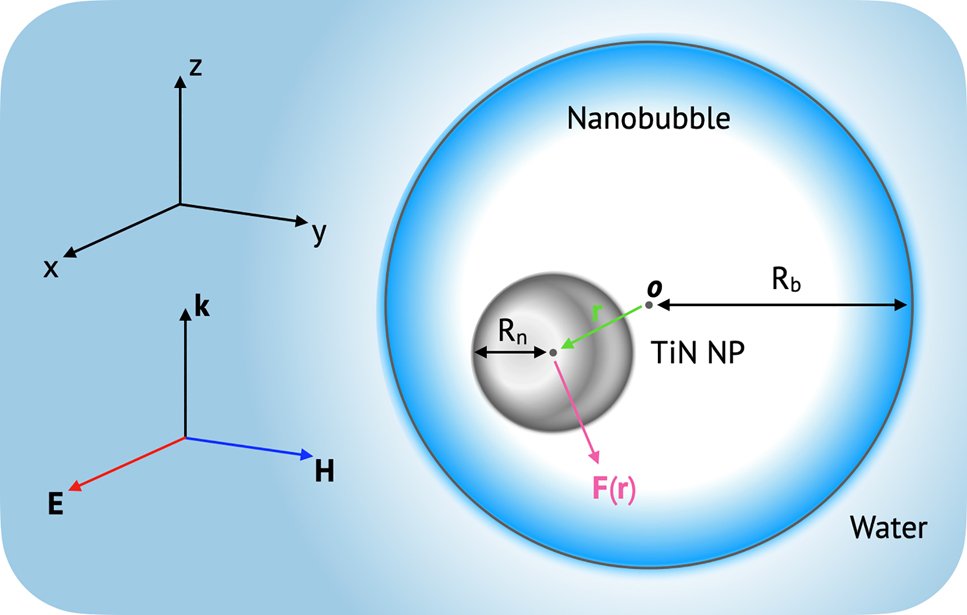
Schematic of optical configuration of a TiN NP in a nanobubble, which is in the medium of water. F(r) is the optical force on the TiN NP, where r is the center of NP. k, E, and H denote the wave vector, the electric field, and the magnetic field of an incident plane wave, respectively.
To quickly evaluate optical conditions enabling the negative optical force, the z-component of optical force

The calculated z-component of optical force on a TiN NP in a nanobubble as a function of the wavelength (λ) of the incident plane wave and R
n. Here, R
b = 150 nm, r = 0, 0, −75 nm, and the amplitude of incident electric field is unity (i.e.,
At the same time, we also investigate the optical absorption properties of the TiN NP in the off-SPR region, and we plot the contour lines of optical absorption quality factor (Q
a) in Figure 2 as well. The optical absorption is vital to forming a nanobubble as it is the factor that the photo-thermal heating rate is proportional to [32]. The temperature of NP should reach a threshold (e.g., the spinodal temperature of the water, 550 K) to be encapsulated by a nanobubble [32]. For estimating the quality factor, we use the Mie theory with the complex optical index of TiN in reference [41] (see Supplementary Information for the details) and assume that a TiN NP is immersed in water. In the wavelength region where the negative optical force appears, the TiN NP has an absorption quality factor of 0.1∼0.5, which is at a promising level to form a photo-thermal nanobubble in experiments. For example, a TiN NP with R
n = 35 nm in the water can reach a temperature of 500–1000 K by a femtosecond pulsed laser with a fluence (F) of 7–24 mJ/cm2 at λ = 1050 nm. These values are comparable to the threshold fluences of silica-core Au–shell NP in water at the SPR peak, where the core–shell NP has exhibited the supercavitating motion in experiments [19, 34]. Also, at the infrared region (800 nm
In the optical condition showing the negative optical force, we choose a state of
To finely track points (
In experiments, upon the illumination of light, the plasmonic NP can get encapsulated by a nanobubble in 1–100 ns (i.e., supercavitating process) by the photo-thermal energy conversion process [33]. In the NP-water suspension, the evolution of nanobubble is a thermodynamically nonequilibrium process involving multiple phases, posing a theoretical difficulty to track the motion of NP in expanding nanobubbles. In this study, without the loss of generality, the vector field line can represent the motion of TiN NP in a nanobubble given following assumption: the NP is instantly encapsulated by a nanobubble of a certain size when it is illuminated by a light source, and then the optical force drives the NP to move in the nanobubble until the NP reaches the nanobubble interface. This assumption is valid since the magnitude of the optical force in real experiments would be 10−12 N–10−14 N [19, 21], which drives the NP to move 0.01–1 nm during the supercavitating process, which lasts 1–100 ns: Stoke’s law considering the steam viscosity (10−5 kg/m s) yields the speed of NP of 10−2 m/s for the optical forces, which corresponds to the travel distance of 0.01–1 nm during the bubble-forming time of 1–100 ns. It is also noted that the motion of NP would be limited by the viscous force of steam in the nanobubble, as the motion of NP is at a low Reynold number of ∼10−3 ≪ 1.
We calculate the vector field line in Eq. (1) by randomly seeding fifty spots of S
0 for the nanobubble with various R
b = 100 nm, 150 nm, 200 nm, and 250 nm, and plot them in Figure 3. With an assigned S
0, a vector field line can be completed by taking the plus (or minus) sign in Eq. (1). On a vector field line, the color corresponds to the normalized z-component of the optical force at a given location, and it can guide us to know the moving direction of NP visually. For example, for the case of R
b = 100 nm, the vector field line denoted as ‘A’ can bring the TiN NP to the light-outgoing interface of nanobubble (the color is close to red, showing that
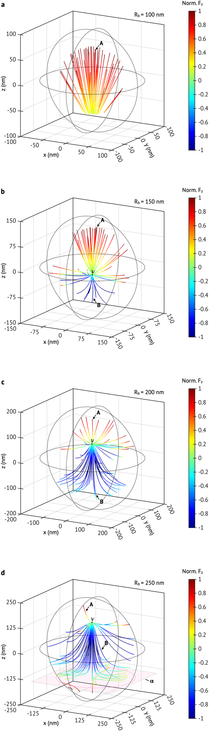
The vector field lines of optical force on a TiN NP in various sizes of nanobubbles: (a) R
b = 100 nm (b) R
b = 150 nm, (c) R
b = 200 nm (d) R
b = 250 nm. In (a) to (d), R
n = 35 nm, and λ = 1050 nm; the color of each vector field line corresponds to the normalized z-component of optical force, which is leveled by the color bar. In (a)–(d), A (or B) denotes the representative vector field line which can guide the TiN NP to the top (or bottom) side of nanobubble;
Meanwhile, a nodal point denoted as ‘
In the nanobubble of R
b = 250 nm, we find that an asymptotic plane (indicated by ‘
From the above results, we assume that there is an ideal range of nanobubble size, where the backward motion of supercavitating NP can be initiated (see Figure 4). The range may be defined as
![Figure 4:
The minimum radius of nanobubble where the nodal point
(
R
ν
)
$\left({R}_{\nu }\right)$
or the asymptotic plane
(
R
α
)
$\left({R}_{\alpha }\right)$
is observed. The region highlighted in gray, which is estimated with the refractive index from [41], indicates the conditions that can potentially initiate the backward ballistic motion of TiN NPs. The blue and green dash (or dot) lines, respectively, indicate the boundary of the sweet zone when the imaginary and the real part of refractive index increase (or decreases) by 10%. The circles indicate the calculated
(
R
α
)
$\left({R}_{\alpha }\right)$
(filled) and
R
ν
${R}_{\nu }$
(opened) of a 35-nm-radius TiN NP with the temperature-dependent refractive index from Reddy et al. [42].](/document/doi/10.1515/nanoph-2021-0503/asset/graphic/j_nanoph-2021-0503_fig_004.jpg)
The minimum radius of nanobubble where the nodal point
In the meantime, it has been reported that the complex refractive index of TiN depends on factors such as temperature [42], or fabricating conditions [43]. We investigate the effect of refractive index variation on the sweet zone where the refractive index taken from reference [40] at λ = 1050 nm is increased (or decreased) by 10%. It finds that the sweet zone is more sensitive to the change of the imaginary part (k) of the refractive index than that of the real part (n) (see Figure 4). The area of the sweet zone can be enlarged (or reduced) when the magnitude of n and k increases (or decreases). However, it is noted that the change of refractive index will not influence the physics inferred from our analysis. In addition, Reddy et al. [42] have reported the variation of the refractive index of TiN thin film with the change of temperature (referred to as Reddy’s index). The temperature-dependent refractive index can be important to the supercavitating TiN NP, as it is based on the photo-thermal energy conversion process. We thus investigate
In conclusion, we study the optical force field on a TiN NP when the NP is in a nanobubble to investigate the possibility of backward motion enabled by a single plane wave at the off-SPR wavelength. Within a nanobubble, a TiN NP with a size smaller than R n = 50 nm can receive a negative optical force, which is needed to achieve backward motion. At the off-SPR region of 800 nm < λ < 1500 nm, the TiN NP (R n < 50 nm) shows the optical absorptions of 0.1 < Q a < 0.5, which is at a promising level to form a nanobubble in experiment. The analysis of the vector field lines of the optical force finds that the nodal point and the asymptotic plane can emerge in a nanobubble, depending on its size. We use this point and this plane to find the range of nanobubble size that can potentially lead to the backward motion of the encapsulated NP. The results from this study may provide valuable information to experimentally realize optical pulling of TiN NPs for potential applications.
Funding source: US National Science Foundation
Award Identifier / Grant number: 2040565
Funding source: Kyung Hee University
Award Identifier / Grant number: KHU-20210736
Funding source: National Research Foundation of Korea
Award Identifier / Grant number: NRF-2021R1C1C1006251
-
Author contribution: All the authors have accepted responsibility for the entire content of this submitted manuscript and approved submission.
-
Research funding: This work was supported by the National Research Foundation of Korea (NRF) grant funded by the Korea government (MSIT) (No. NRF-2021R1C1C1006251). This work was supported by a grant from Kyung Hee University in 2021 (KHU-20210736). T.L. would like to thank the US National Science Foundation (2040565) for support.
-
Conflict of interest statement: The authors declare no conflicts of interest.
-
Data availability: Data underlying the results presented in this paper are not publicly available at this time but may be obtained from the authors upon reasonable request.
References
[1] P. D. Howes, R. Chandrawati, and M. M. Stevens, “Colloidal nanoparticles as advanced biological sensors,” Science, vol. 346, p. 1247390, 2014. https://doi.org/10.1126/science.1247390.Suche in Google Scholar PubMed
[2] A. De La Escosura-Muñiz and A. Merkoçi, “A nanochannel/nanoparticle-based filtering and sensing platform for direct detection of a cancer biomarker in blood,” Small, vol. 7, pp. 675–682, 2011.10.1002/smll.201002349Suche in Google Scholar PubMed
[3] R. Singh and J. W. Lillard, “Nanoparticle-based targeted drug delivery,” Exp. Mol. Pathol., vol. 86, pp. 215–223, 2009. https://doi.org/10.1016/j.yexmp.2008.12.004.Suche in Google Scholar PubMed PubMed Central
[4] P. Tiwari, K. Vig, V. Dennis, et al.., “Functionalized gold nanoparticles and their biomedical applications,” Nanomaterials, vol. 1, pp. 31–63, 2011. https://doi.org/10.3390/nano1010031.Suche in Google Scholar PubMed PubMed Central
[5] W. Cheng, N. Park, M. T. Walter, M. R. Hartman, and D. Luo, “Nanopatterning self-assembled nanoparticle superlattices by moulding microdroplets,” Nat. Nanotechnol., vol. 3, pp. 682–690, 2008. https://doi.org/10.1038/nnano.2008.279.Suche in Google Scholar PubMed
[6] L. Lin, X. Peng, Z. Mao, et al.., “Bubble-pen lithography,” Nano Lett., vol. 16, pp. 701–708, 2016. https://doi.org/10.1021/acs.nanolett.5b04524.Suche in Google Scholar PubMed PubMed Central
[7] Q. Zhang, Y. Pang, J. Schiffbauer, et al.., “Light-guided surface plasmonic bubble movement via contact line de-pinning by in-situ deposited plasmonic nanoparticle heating,” ACS Appl. Mater. Interfaces, vol. 11, pp. 48525–48532, 2019. https://doi.org/10.1021/acsami.9b16067.Suche in Google Scholar PubMed
[8] Q. Zhang, R. D. Neal, D. Huang, et al.., “Surface bubble growth in plasmonic nanoparticle suspension,” ACS Appl. Mater. Interfaces, vol. 12, pp. 26680–26687, 2020. https://doi.org/10.1021/acsami.0c05448.Suche in Google Scholar PubMed
[9] J. Katuri, X. Ma, M. M. Stanton, and S. Sánchez, “Designing micro-and nanoswimmers for specific applications,” Acc. Chem. Res., vol. 50, pp. 2–11, 2017. https://doi.org/10.1021/acs.accounts.6b00386.Suche in Google Scholar PubMed PubMed Central
[10] J. Wang, Z. Xiong, J. Zheng, X. Zhan, and J. Tang, “Light-driven micro/nanomotor for promising biomedical tools: principle, challenge, and prospect,” Acc. Chem. Res., vol. 51, pp. 1957–1965, 2018. https://doi.org/10.1021/acs.accounts.8b00254.Suche in Google Scholar PubMed
[11] S. Nain and N. N. Sharma, “Propulsion of an artificial nanoswimmer: a comprehensive review,” Front. Life Sci., vol. 8, pp. 2–17, 2015. https://doi.org/10.1080/21553769.2014.962103.Suche in Google Scholar
[12] D. G. Grier, “A revolution in optical manipulation,” Nature, vol. 424, pp. 810–816, 2003. https://doi.org/10.1038/nature01935.Suche in Google Scholar PubMed
[13] A. Ashkin, “Forces of a single-beam gradient laser trap on a dielectric sphere in the ray optics regime,” Biophys. J., vol. 61, pp. 569–582, 1992. https://doi.org/10.1016/s0006-3495(92)81860-x.Suche in Google Scholar PubMed PubMed Central
[14] Y. Roichman, B. Sun, Y. Roichman, J. Amato-Grill, and D. G. Grier, “Optical forces arising from phase gradients,” Phys. Rev. Lett., vol. 100, 2008, Art no. 013602. https://doi.org/10.1103/PhysRevLett.100.013602.Suche in Google Scholar PubMed
[15] L. Allen, M. W. Beijersbergen, R. J. C. Spreeuw, and J. P. Woerdman, “Orbital angular momentum of light and the transformation of Laguerre-Gaussian laser modes,” Phys. Rev. A, vol. 45, pp. 8185–8189, 1992. https://doi.org/10.1103/physreva.45.8185.Suche in Google Scholar PubMed
[16] O. Brzobohatý, V. Karásek, M. Šiler, L. Chvátal, T. Čižmár, and P. Zemánek, “Experimental demonstration of optical transport, sorting and self-arrangement using a ‘tractor beam,’” Nat. Photonics, vol. 7, pp. 123–127, 2013.10.1038/nphoton.2012.332Suche in Google Scholar
[17] S.-H. Lee, Y. Roichman, and D. G. Grier, “Optical solenoid beams,” Opt. Express, vol. 18, p. 6988, 2010. https://doi.org/10.1364/oe.18.006988.Suche in Google Scholar
[18] D. B. Ruffner and D. G. Grier, “Optical conveyors: a class of active tractor beams,” Phys. Rev. Lett., vol. 109, p. 163903, 2012. https://doi.org/10.1103/physrevlett.109.163903.Suche in Google Scholar
[19] E. Lee, D. Huang, and T. Luo, “Ballistic supercavitating nanoparticles driven by single Gaussian beam optical pushing and pulling forces,” Nat. Commun., vol. 11, pp. 1–8, 2020. https://doi.org/10.1038/s41467-020-16267-9.Suche in Google Scholar PubMed PubMed Central
[20] Q. Zhang, R. Li, E. Lee, and T. Luo, “Optically driven gold nanoparticles seed surface bubble nucleation in plasmonic suspension,” Nano Lett., vol. 21, p. 5492, 2021. https://doi.org/10.1021/acs.nanolett.0c04913.Suche in Google Scholar PubMed
[21] E. Lee and T. Luo, “Long-distance optical pulling of nanoparticle in a low index cavity using a single plane wave,” Sci. Adv., vol. 6, 2020, Art no. eaaz3646. https://doi.org/10.1126/sciadv.aaz3646.Suche in Google Scholar PubMed PubMed Central
[22] V. Kajorndejnukul, W. Ding, S. Sukhov, C.-W. Qiu, and A. Dogariu, “Linear momentum increase and negative optical forces at dielectric interface,” Nat. Photonics, vol. 7, pp. 787–790, 2013. https://doi.org/10.1038/nphoton.2013.192.Suche in Google Scholar
[23] G. Guo, T. Feng, and Y. Xu, “Tunable optical pulling force mediated by resonant electromagnetic coupling,” Opt. Lett., vol. 43, p. 4961, 2018. https://doi.org/10.1364/ol.43.004961.Suche in Google Scholar PubMed
[24] A. Mizrahi and Y. Fainman, “Negative radiation pressure on gain medium structures,” Opt. Lett., vol. 35, p. 3405, 2010. https://doi.org/10.1364/ol.35.003405.Suche in Google Scholar PubMed
[25] K. J. Webb and Shivanand, “Negative electromagnetic plane-wave force in gain media,” Phys. Rev. E, vol. 84, 2011, Art no. 057602. https://doi.org/10.1103/PhysRevE.84.057602.Suche in Google Scholar PubMed
[26] L. Lin, P. S. Kollipara, A. Kotnala, et al.., “Opto-thermoelectric pulling of light-absorbing particles,” Light Sci. Appl., vol. 91, no. 9, pp. 1–11, 2020. https://doi.org/10.1038/s41377-020-0271-6.Suche in Google Scholar PubMed PubMed Central
[27] J. Chen, J. Ng, Z. Lin, and C. T. Chan, “Optical pulling force,” Nat. Photonics, vol. 5, pp. 531–534, 2011. https://doi.org/10.1038/nphoton.2011.153.Suche in Google Scholar
[28] S. Sukhov and A. Dogariu, “Negative nonconservative forces: optical “tractor beams” for arbitrary objects,” Phys. Rev. Lett., vol. 107, p. 203602, 2011. https://doi.org/10.1103/physrevlett.107.203602.Suche in Google Scholar
[29] A. Novitsky, C.-W. Qiu, and H. Wang, “Single gradientless light beam drags particles as tractor beams,” Phys. Rev. Lett., vol. 107, p. 203601, 2011. https://doi.org/10.1103/physrevlett.107.203601.Suche in Google Scholar PubMed
[30] A. Dogariu, S. Sukhov, and J. Sáenz, “Optically induced “negative forces”,” Nat. Photonics, vol. 7, pp. 24–27, 2013. https://doi.org/10.1038/nphoton.2012.315.Suche in Google Scholar
[31] J. Damková, L. Chvátal, J. Ježek, J. Oulehla, O. Brzobohatý, and P. Zemánek, “Enhancement of the ‘tractor-beam’ pulling force on an optically bound structure,” Light Sci. Appl., vol. 7, pp. 17135, 2018.10.1038/lsa.2017.135Suche in Google Scholar PubMed PubMed Central
[32] K. Metwally, S. Mensah, and G. Baffou, “Fluence threshold for photothermal bubble generation using plasmonic nanoparticles,” J. Phys. Chem. C, vol. 119, pp. 28586–28596, 2015. https://doi.org/10.1021/acs.jpcc.5b09903.Suche in Google Scholar
[33] E. Lukianova-Hleb, Y. Hu, L. Latterini, et al.., “Plasmonic nanobubbles as transient vapor nanobubbles generated around plasmonic nanoparticles,” ACS Nano, vol. 4, pp. 2109–2123, 2010. https://doi.org/10.1021/nn1000222.Suche in Google Scholar PubMed PubMed Central
[34] R. Lachaine, C. Boutopoulos, P.-Y. Lajoie, É. Boulais, and M. Meunier, “Rational design of plasmonic nanoparticles for enhanced cavitation and cell perforation,” Nano Lett, vol. 16, pp. 3187–3194, 2016. https://doi.org/10.1021/acs.nanolett.6b00562.Suche in Google Scholar PubMed
[35] G. Lagubeau, M. Le Merrer, C. Clanet, and D. Quéré, “Leidenfrost on a ratchet,” Nat. Phys., vol. 7, pp. 395–398, 2011. https://doi.org/10.1038/nphys1925.Suche in Google Scholar
[36] Y. Roichman, A. Waldron, E. Gardel, and D. G. Grier, “Optical traps with geometric aberrations,” Appl. Opt., vol. 45, pp. 3425–3429, 2006. https://doi.org/10.1364/ao.45.003425.Suche in Google Scholar PubMed
[37] Y. Pang, J. Zhang, R. Ma, Z. Qu, E. Lee, and T. Luo, “Solar–thermal water evaporation: a review,” ACS Energy Lett, vol. 5, pp. 437–456, 2020. https://doi.org/10.1021/acsenergylett.9b02611.Suche in Google Scholar
[38] J. H. Hodak, A. Henglein, M. Giersig, and G. V. Hartland, “Laser-Induced inter-diffusion in AuAg core-shell nanoparticles,” J. Phys. Chem. B, vol. 104, pp. 11708–11718, 2000. https://doi.org/10.1021/jp002438r.Suche in Google Scholar
[39] U. Guler, V. M. Shalaev, and A. Boltasseva, “Nanoparticle plasmonics: going practical with transition metal nitrides,” Mater. Today, vol. 18, pp. 227–237, 2015. https://doi.org/10.1016/j.mattod.2014.10.039.Suche in Google Scholar
[40] A. Salandrino, S. Fardad, and D. N. Christodoulides, “Generalized Mie theory of optical forces,” J. Opt. Soc. Am. B, vol. 29, p. 855, 2012. https://doi.org/10.1364/josab.29.000855.Suche in Google Scholar
[41] J. Pflüger, J. Fink, W. Weber, K. P. Bohnen, and G. Crecelius, “Dielectric properties of dielectric properties of TiCx, TiNx, VCx, and VNx from 1.5 to 40 eV determined by electron-energy-loss spectroscopy,” Phys. Rev. B, vol. 30, p. 1155, 1984.10.1103/PhysRevB.30.1155Suche in Google Scholar
[42] H. Reddy, U. Guler, Z. Kudyshev, A. V. Kildishev, V. M. Shalaev, and A. Boltasseva, “Temperature-dependent optical properties of plasmonic Titanium Nitride thin films,” ACS Photonics, vol. 4, pp. 1413–1420, 2017. https://doi.org/10.1021/acsphotonics.7b00127.Suche in Google Scholar
[43] M. Popović, M. Novaković, M. Mitrić, K. Zhang, and N. Bibić, “Structural, optical and electrical properties of argon implanted TiN thin films,” Int. J. Refract. Met. Hard Mater., vol. 48, pp. 318–323, 2015.10.1016/j.ijrmhm.2014.09.026Suche in Google Scholar
© 2021 Eungkyu Lee and Tengfei Luo, published by De Gruyter, Berlin/Boston
This work is licensed under the Creative Commons Attribution 4.0 International License.
Artikel in diesem Heft
- Frontmatter
- Review
- Recent advances of wide-angle metalenses: principle, design, and applications
- Research Articles
- Conditions for establishing the “generalized Snell’s law of refraction” in all-dielectric metasurfaces: theoretical bases for design of high-efficiency beam deflection metasurfaces
- Highly ordered arrays of hat-shaped hierarchical nanostructures with different curvatures for sensitive SERS and plasmon-driven catalysis
- Extended bound states in the continuum in a one-dimensional grating implemented on a distributed Bragg reflector
- Improved localization precision via restricting confined biomolecule stochastic motion in single-molecule localization microscopy
- Vector optomechanical entanglement
- Negative optical force field on supercavitating titanium nitride nanoparticles by a single plane wave
- Local nonlinearity engineering of evanescent-field-interaction fiber devices embedding in black phosphorus quantum dots
- Terahertz toroidal metasurface biosensor for sensitive distinction of lung cancer cells
- Imaging-based optical barcoding for relative humidity sensing based on meta-tip
- Two-dimensional array of iron-garnet nanocylinders supporting localized and lattice modes for the broadband boosted magneto-optics
- Generation and dynamics of soliton and soliton molecules from a VSe2/GO-based fiber laser
- Band structure tuning of g-C3N4 via sulfur doping for broadband near-infrared ultrafast photonic applications
- Observing multifarious topological phase transitions with real-space indicator
- Crossing the light line