Innovative prevention of stress corrosion crack propagation in nuclear power pipe welds
-
Xiaofei Kong
Xiaofei Kong, born in 1984, graduated with a doctorate degree in Mechanics from the ENI Saint Etienne, France, in 2012. Then, he worked at the Technical Center Europe, France in 2013. At the end of 2015, he returned to China, worked at China Nuclear Power Engineering Co., Ltd, and engaged in reactor structural design and calculation.
Xin Wang, born in 1966. Currently, he is a chief engineer at China Nuclear Power Design Co., Ltd, and mainly engaged in the research and design of nuclear power models.
Bingchi Lin, born in 1992, graduated with an engineering master’s degree from Sun Yat-sen University in 2017. Then, he worked at China Nuclear Power Engineering Co., Ltd, and engaged in reactor structural design and calculation.
Zhiliang Xiong, born in 1990, graduated with a master’s degree from Harbin Institute of Technology in 2014. Then, he worked at China Nuclear Power Engineering Co., Ltd, and engaged in welding design and maintenance technology for nuclear power equipments.
Xiaoyun Deng, born in 1967. Currently, he is a director of the Nuclear Island Equipments Institute of China Nuclear Power Engineering Co., Ltd., and mainly engaged in research and design of nuclear island equipment, as well as research nuclear power materials.
Xiao Li, born in 1969, graduated with an MSc from the School of Material Science and Engineering, Xi’an Shiyou University in 1999. Currently, she is a Professor in the same faculty. Her main research areas are welding residual stress, deformation control and the finite element analysis of welded joints.
Yongxin Lu, born 1986, graduated with a doctor degree from the School of Materials Science and Engineering, Tianjin University, China, in 2017. Then, he worked in the School of Materials Science and Engineering, Xi’an Shiyou University, China. Currently, he is lecturer and his main research areas are control and simulation of welding deformation and friction stir welding.

Abstract
Failure caused by stress corrosion cracking (SCC) is inevitable during the long-term service of nuclear power pipe welds. This is mainly due to the propagation of microcracks in the deposited metal, which seriously affects the operation safety of nuclear power pressure pipes. Overlay welding is practical for pressure pipe repair welding, which can introduce compressive residual stress inside the weld seam. In this work, a diagonal T-pipe joint was fabricated using tungsten inert gas arc welding with ERRS-3 wire, and an overlay weld was also fabricated using tungsten inert gas arc welding with ERRS-3 wire under circumstances of water in the pipe and no water in the pipe. And then the contour method and finite element method were employed to measure and calculate the residual stress distribution in the diagonal T-pipe joint. Both results showed that overlay welding can introduce compressive residual stresses into the pipe joint. The compressive residual stress zone area inside the weld seam with water in the pipe is larger than that without water in the pipe, and the compressive residual stress zone area varies at different positions of the weld seam. This work is expected to promote the application of overlay weld technology in the diagonal T-shaped pipe joint repair and prevent stress corrosion crack propagation of nuclear power pipe welds.
1 Introduction
TUE250B has been widely used in nuclear industry applications due to its good weldability and mechanical properties. And one of the most important applications is the T-shaped pipe. However, micro cracks are always observed in the weld of T-shaped pipe joints due to the long-term operation, and this is easy to cause stress corrosion crack propagation inside the weld seam [1], [2], [3]. To prolong the service life of T-shaped pipe joints and improve the operation safety of pipelines, overlay welding repair is often used for introducing compressive residual stresses into stainless-steel welded joints [4]. But non-uniform heating and cooling temperature filed applied in the welding processes, produce a non-uniform residual stresses field in the weld structures [5], [6], [7], [8], [9]. Thus more and more attention is paid to residual stresses in the overlay weld, in both academic and industry fields.
The distribution of residual stresses induced by the overlay weld is very complex due to multi-layer, multi-pass, and the different thermal physical, and mechanical properties between the overlay weld and the base metal [10]. Generally, the effect of overlay weld on the residual stress in the T-shaped pipe joint is greater than that of initial weld residual stress, and a more complex residual stress distribution is generated in the T-shaped pipe joint. Thus, a clear understanding of the evolution mechanism of residual stress during the overlay weld is crucial to guarantee the quality of the T-shaped pipe joint and prevent stress corrosion crack propagation of nuclear power pipe welds.
So far, very little work has been carried out on the overlay weld through modern computational welding mechanics [11, 12]. Amudha et al. [13] studied the distribution of the cladding residual stress on the surface of low-carbon steel using a traditional heat source model, and found that the residual stress of the surfacing layer decreased with the increase of the number of surface layers. Udagawa et al. [14] studied the residual stress distribution of surfacing layers, and it is found that the surfacing layer mainly produces tensile residual stress, and the residual stress near the interface between the surfacing layer and the matrix has a sudden change and a large stress gradient, which is the weak zone of the cladding structure. Jiang et al. [15], [16], [17], [18], [19] made a larger number of investigations on the repair welding residual stress of stainless steel/low carbon steel clad plate, and found that the repaired residual stresses can be decreased by changing heat input, welding layer, repair length, repair depth, repair width, clad metal thickness, and base metal thickness. Song et al. [20] carried out an in-depth investigation of repair weld geometry effects on residual stress distributions of girth weld with considering original welding residual stresses. They concluded that a weld repair should be designed as long as possible, narrow as possible, and shallow as possible. Saukkonen et al. [21] researched the residual stress distribution in the weld cross-section by a contour method, and the residual stress distribution is used to evaluate the EAC susceptibility of various areas of the pipe weld. Hicks et al. [22] evaluated the residual stresses induced by repairs to small-diameter stainless steel pipe welds. The results show that repair welds markedly increase the magnitude of the tensile axial residual stresses for weld configurations. Therefore, the influence of overlay welding on the distribution of residual stress in the original weld seam is still unclear, and whether overlay welding can prevent stress corrosion crack propagation in the original weld needs further research.
For the diagonal T-shaped pipe joint, if compressive stress can be formed at the microcrack zone of the weld, the propagation of microcracks would be hindered, and the possibility of its expansion can be eliminated. Therefore, TUE250B was used for overlay welding repair outside the diagonal T-shaped pipe joint under the condition of water in the pipe and no water in the pipe in this work. Additionally, to determine the effect of weld repairing, the residual stress in the diagonal T-shaped pipe joint was measured via the contour method and was calculated by the finite element method, respectively. It is expected that this study would propel the application of the overlay weld in the T-shaped pipe joint repair and prevent stress corrosion crack propagation of nuclear power pipe welds.
2 Materials, geometry and welding process
Residual stress measurements were carried out on a test component manufactured from a TUE250B diagonal T-pipe joint. The outside diameter, thickness, and length of the main pipe are 323.85, 7.14, and 335 mm, respectively. The diameter of the branch pipe is 44 mm; its wall thickness is 9 mm. The position of the overlay weld is shown in Figure 1 and the final component is shown in Figure 2.

The position of the overlay weld.

Sample morphology, a) T-shaped pipe joint without water in the pipe, b) T-shaped pipe joint with water in the pipe.
The main pipe and branch pipe were mounted together and welded with the tungsten inert gas (TIG) method using an ER70S-3 filling wire with a diameter of 1.6 mm. Stress-relieving heat treatment (for 0.5 h at 650 °C followed by air cooling) was conducted on the diagonal T-pipe joint to eliminate the welding stress. Subsequently, overlay welding was carried out using manual argon tungsten arc welding, and a 1.6 mm ER316L welding wire was adopted. The test component dimensions were shown in Table 1 and welding parameters were shown in Tables 2 and 3. These welding parameters are the best welding parameters optimized by experiments. The diagonal T-joint without water in the pipe was fixed to the worktable, and the diagonal T-joint with water in the pipe was fixed to the water-cooled bench, both are vertical welding positions, and the left and right sides are welded symmetrically.
Summary of the test component dimensions.
| Component | Base material | Outer radius, R0 (mm) | Wall thickness, t (mm) | Length, L (mm) |
|---|---|---|---|---|
| Main pipe | TUE250B | 323.85 | 7.14 | 335 |
| Branch pipe | TUE250B | 44 | 9 | 85 |
Summary of the overlay welding parameters without water in the pipe.
| Weld layer | Weld type | Peak current (A) | Base current (A) | Voltage (V) | Diameter of the wire (mm) | Welding speed (mm min−1) | Maximum heat input (J mm−1) | Interlayer temperature (°C) |
|---|---|---|---|---|---|---|---|---|
| 1 | GTAW | 85–93 | 65–70 | 9–12 | 1.6 | 20–60 | 1400 | ≤100 |
| 2 | GTAW | 90–99 | 70–77 | 9–12 | 1.6 | 20–60 | 1400 | ≤100 |
| 3 | GTAW | 100–110 | 80–88 | 9–12 | 1.6 | 20–60 | 1500 | ≤200 |
| n | GTAW | 104–115 | 85–93 | 9–12 | 1.6 | 20–60 | 1500 | ≤200 |
Summary of the overlay welding parameters with water in the pipe.
| Weld layer | Weld type | Peak current (A) | Base current (A) | Voltage (V) | Diameter of the wire (mm) | Welding speed (mm min−1) | Maximum heat input (J mm−1) | Interlayer temperature (°C) |
|---|---|---|---|---|---|---|---|---|
| 1 | GTAW | 90–100 | 65–70 | 10–11 | 1.6 | 30–40 | 1089 | ≤100 |
| 2 | GTAW | 100–110 | 70–77 | 10–11 | 1.6 | 40–50 | 1716 | ≤100 |
| 3 | GTAW | 105–115 | 75–85 | 11–12 | 1.6 | 50–60 | 1584 | ≤100 |
| n | GTAW | 110–120 | 80–90 | 11–12 | 1.6 | 50–60 | 1656 | ≤100 |
3 Residual stress measurement and calculation
3.1 Residual stress measurement for repairing a diagonal T-pipe joint
The contour method was used to measure the residual stress distribution in the diagonal T-pipe joints. The measurement process involves cutting along the measuring circumferential section, scanning the profile of the cut section, smoothing the measurement data, and calculating the normal stress in the original cut section with the finite element method.
Section cutting was conducted via EDM (Sanguang Technology Co., Ltd, Suzhou, China) using a 0.2 mm pure copper cutting wire at a speed of 0.2 mm min−1, and the sample was cooled with deionized water. The sample deformation will affect the cutting accuracy and measurement accuracy by reason of the stress release during the cutting process. Therefore, the clamping position was set to close to the cutting position [23]. After cutting, the sample surface was cleaned using an ultrasonic cleaner (Xinxin ultrasonic electronic equipment Co., Ltd, Jining, China) to remove oil and other impurities, and the sample was dried using an electric blower. The contour can be measured using contact, optical, or electromagnetic methods [24]. Among these, the contact and optical measurement methods are the most widely used. In this work, a Steinbichler COMET L3D (Steinbichler Optotechnik Gmbh, Neubeuern, Germany) was used for the non-contact measurements, its measuring principle is based on blue light interference. The standard pattern was used for calibration before the measurements, and the distance between the measuring points was set to be less than 170 μm.
ABAQUS (Dassault Systems, Paris, French) was used to calculate the residual stress. As the stress release process is an elastic deformation process, the procedure to calculate the stress generally adopts a linear elastic analysis model [25], [26], [27]. The analysis model and boundary conditions are shown in Figure 3. The results of the profile measurement can only reflect the normal displacement of the cut section, and the X and Y displacement in the cutting section cannot be measured. Therefore, the in-plane displacement in the cutting section is not constrained during the stress analysis process, which indicates that the in-plane shear stress is zero. After the measured normal displacement is applied to nodes in the cutting section, the normal stress on the cutting section can be obtained by elastic calculation, which is the original residual stress in the cutting section.

Boundary condition of diagonal T-pipe joint using the contour method.
3.2 Residual stress calculation for repairing a diagonal T-pipe joint
A finite element model of diagonal T-pipe joint repairing was built with Solid-works software, and the analysis model and boundary conditions are shown in Figure 4. The dimension of the model is consistent with that of the welded joint, and the refined meshes were created in the weld and its adjacent region. The residual stress of the diagonal T-pipe joint was calculated by the finite element method with Abaqus software, and the mesh is hexahedron, and the number of mesh is 145,642. The thermophysical properties of the used ER70S-3 are listed in Table 4.

Boundary condition of diagonal T-pipe joint using the finite element method.
The thermophysical properties of the used ER70s steel.
| Temperature (°C) | Density (kg m−3) | Thermal conductivity (W m−1 K) | Specific heat (J kg−1 K−1) | Elastic modulus (MPa) | Poisson’s ratio | Thermal expansion coefficient (10−6 K−1) | Yield strength (MPa) |
|---|---|---|---|---|---|---|---|
| 25 | 7810 | 54 | 423 | 2.1 × 10⁵ | 0.29 | 11.1 | 420 |
| 250 | 7790 | 52 | 473 | 2.0 × 10⁵ | 0.29 | 12.2 | 355 |
| 500 | 7670 | 47 | 536 | 1.8 × 10⁵ | 0.29 | 13.6 | 260 |
| 750 | 7610 | 28 | 662 | 1.1 × 10⁵ | 0.29 | 15.1 | 97 |
| 1000 | 7520 | 32 | 785 | 3.8 × 10⁴ | 0.29 | 15.2 | 12 |
The heat transfer boundary condition is very important to the temperature field calculation of the welding process. In general, there are three kinds of heat emission modes, which are heat conduction, heat radiation, and heat convection. The total heat transfer coefficient of the outside surface h0 is equal to the sum of the convection and radiation coefficient and can be expressed as follows: h0 = 0.8 × 5.67 × 10−8 (T4 −
Besides, a double ellipsoid heat source model was selected for the simulation of weld passes, which can be expressed as follows:
with q1 and q2: heat densities at any point (x, y, z) at time t inside the front (1) and rear (2) half ellipsoids, η: heat efficiency, U and I: welding voltage and current, respectively, f1 and f2: heat distribution function of the front and rear half ellipsoids, which can be determined by f1 + f2 = 2, a1, a2, b, and c: dimensions of the double ellipsoid and v: welding velocity.
4 Results and discussion
4.1 Residual stress of the diagonal T-pipe joint repair without water in the pipe
The cut section of the contour method is a circumferential section passing through the center of the branch pipe, as shown in Figure 5. The stress results of the contour method yielded normal stress for the cut section, which corresponds to axial stress in the main pipe and circumferential stress in the branch pipe, and longitudinal stress in the overlay weld. Figure 5 shows the measurement results for the cut section. The wall thickness of the steel pipe is very thin, and there is obvious tensile stress on the inner wall of the main pipe at the joint. However, there is an obvious compressive stress in the middle of the original weld, which can effectively prevent crack growth in the weld.

Residual stress distribution of diagonal T-pipe joint using the contour method.
Figure 6 shows the calculation results for the cut section using the finite element method. It can be seen that the overall distribution of residual stress is similar to that of the contour method, and high tensile stress occurs at the inner wall of the main pipe. The residual stress at the joint is distributed in layers in the direction of the branch pipe. From the inner wall to the weld toe of the main pipe, there are multiple alternations of tensile stress + compressive stress + tensile stress. This state is directly related to the welding process and the size of the branch pipe and main pipe.
Residual stress distribution of diagonal T-pipe joint using the finite element method.
Further, the residual stress distribution on different paths in the area near the diagonal T-joint with the contour method is extracted as shown in Figure 7. Path 1 is on the outer surface of the weld, starting from the weld toe of the branch pipe and ending at the weld toe of the main pipe, on which it can be found that residual stress is basically tensile stress and gradually decrease towards the weld toe of the main pipe, and the peak tensile stress is about 160 MPa and near to weld toe of the branch pipe. Path 2–Path 5 passes through the original weld and overlay, where Path 2 and Path 5 are the fusion lines with the branch pipe and main pipe respectively, and the distance between the paths is approximately 6 mm. The residual stress on Path 2 is almost tensile stress, but low compressive stress can be observed in the middle of the Path, which is located within the original welding zone. The same phenomenon occurs on Path 3–Path 5, but the value of compressive stress is larger and the compressive stress range is wider. The compressive range on the Path 5 is almost 15 mm, and the width covers almost the entire original weld.

Residual stress distribution on different paths in the area near the diagonal T-joint using the contour method, a) residual stress distribution and paths, b) residual stress distribution on path 1, and c) residual stress distribution on paths 2–5.
The residual stress distribution on different paths in the area near the T-joint with the finite element method is also extracted as shown in Figure 8. The stress change rule on each path is similar to the result of the contour method. This fully shows that when the diagonal T-shaped pipe joint is repaired without water in the pipe, there must be compressive residual stress in the fillet weld. The peak value of this compressive stress can reach about 150 MPa, which can effectively prevent crack growth in the weld.

Residual stress distribution on different paths in the area near the diagonal T-joint using the finite element method, a) residual stress distribution of pipe joint, b) residual stress distribution on path 1, and c) residual stress distribution on paths 2–5.
In addition, the residual stresses on two sections 3 mm from the cutting surface of the contour method were also observed, as shown in Figure 9, the compressive residual stress zone is generated inside the welded joint. The area of the compressive residual stress zone is 94 mm2, 107 mm2, and 49 mm2, respectively, for plane 1, the cut section, and plane 2. Although the area of compressive residual stress zone on different sections of pipe joint is different, overlay weld can introduce compressive residual stresses inside the weld seam.

Residual stress distribution of pipe joint from different locations with no water in the pipe, a) observed locations, b) residual stress distribution in plane 1, c) residual stress distribution in cut section, and d) residual stress distribution in plane 2.
4.2 Residual stress of diagonal T-pipe joint repair with water in the pipe
Figure 10 shows the measurement results of the cut section with the contour method, and the cut section is consistent with that without water in the pipe. The residual stress distribution in the welded joint is also similar to that in the pipe without water, but the area of residual tensile stress and compressive stress is more concentrated than that in the pipe without water. The maximum tensile stress is located in the area near the toe of the overlay weld and the peak value of residual tensile stress is higher than that in the pipe without water, which is about 350 MPa. Compressive stress can also be observed in the original weld. Compared with the results without water in the pipe, the compressive stress area is larger, and the peak value of compressive residual stress is higher than that without water in the pipe, which is about 260 MPa.

Residual stress distribution of diagonal T-pipe joint repairing underwater in the pipe using the contour method.
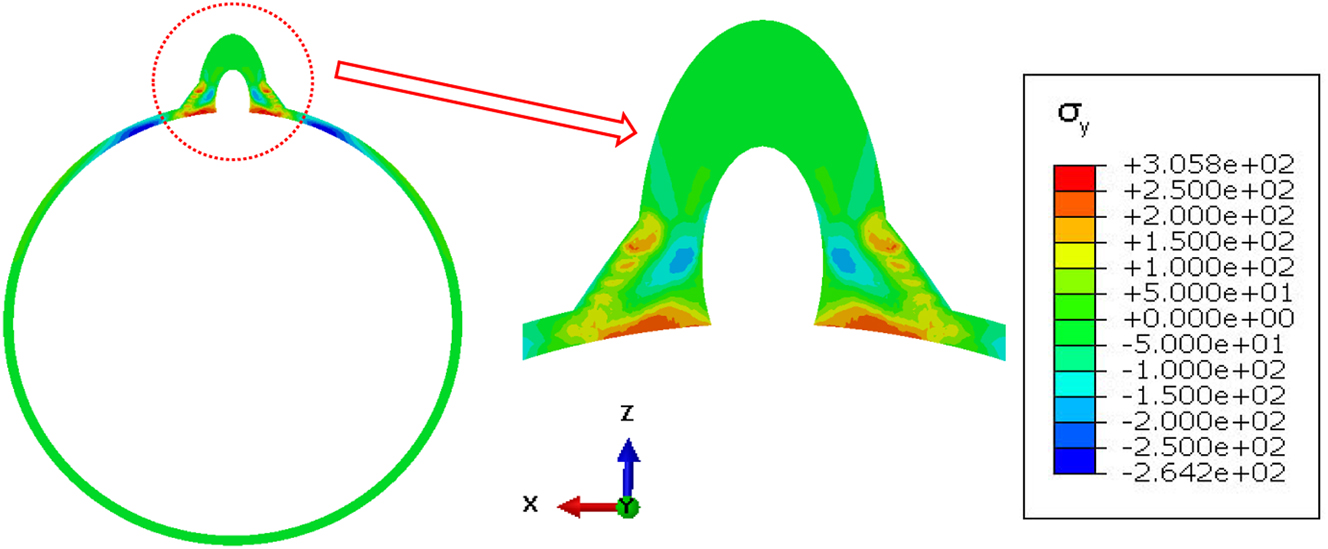
Figure 11 shows the calculation results for the cut surfaces using the finite element method. It can be seen that the overall distribution of residual stress is similar to that of the contour method, and high tensile stress occurs at the area near the toes of the overlay weld. The residual stress at the joint is distributed in layers in the direction of the branch pipe. From the inner wall to the weld toe of the main pipe, there are multiple alternations of tensile stress + compressive stress + tensile stress. This state is similar to that of the contour method. And the peak of residual tensile stress and residual compressive stress with the finite element method is similar to that with the contour method.

Residual stress distribution of diagonal T-pipe joint repairing underwater in the pipe using the finite element method.
The distribution of residual stress on the outer surface of the overlay weld is shown in the Figures 12 and 13. The change of residual tensile stress of Path 1 with the contour method is similar to that with the finite element method. The maximum tensile stress is about 225 MPa, and the minimum tensile stress is about 90 MPa. The change of residual tensile stress of Path 2, Path 3, Path 4, and Path 5 with the contour method is also similar to that with the finite element method. It can be seen that the residual stress gradually changes from compressive stress to tensile stress from the inner wall of the branch pipe to the outer wall of the surfacing layer. Compared with the T-pipe joint repairing without water in the pipe, the area of residual tensile stress zone on the main pipe is significantly reduced, and repairing with water in the pipe can be conducive to reducing the area of residual tensile stress in the weld zone and increase the area of residual compressive stress in the weld zone. Besides, the residual stress peak value of Path 1–5 is different without water in the pipe and with water in the pipe. The residual stress peak value with water in the pipe is higher than that without water in the pipe. The maximum tensile stress of Path 1 can reach 220 MPa, the residual tensile stress peak value of Path 2–5 can reach 225 MPa, and the residual compress stress peak value of Path 3–4 can reach −280 MPa.

Residual stress distribution on different paths in the area near the diagonal T-joint using the contour method, a) residual stress distribution and paths, b) residual stress distribution in path 1, c) residual stress distribution in paths 2–5.

Residual stress distribution on different paths in the area near the diagonal T-joint using the finite element method, a) residual stress distribution and paths, b) residual stress distribution in path 1, c) residual stress distribution in paths 2–5.
The distribution of residual stress from different locations with water in the pipe is observed, as shown in Figure 14, there is an obvious compressive residual stress zone inside the weld seam. The area of the compressive residual stress zone is 204 mm2, 213 mm2, and 178 mm2 respectively for plane 1, cut section, and plane 2, which are all greater than that without water in the pipe. It can be concluded that water in the pipe plays an important role in fast cooling, and it leads to a high level and large range of compressive residual stress.

Residual stress distribution of pipe joints from different locations with no water in the pipe, a) observed locations, b) residual stress distribution in plane 1, c) residual stress distribution in the cut section, and d) residual stress distribution in plane 2.
5 Conclusions
To explore the effect of overlay welding on the residual stress of a diagonal T-pipe joint, a TUE250B diagonal T-pipe joint was fabricated with TIG welding using ER70S-3 filling wire. After stress relief heat treatment, a 10 mm-thick overlay weld was fabricated on the original weld surface, and the residual stress was measured with the contour method and was calculated with the finite element method. The results can be summarized as follows.
Compressive residual stress can be introduced in the original ER70S-3 weld during overlay welding, which is a benefit for preventing stress corrosion crack propagation in the weld.
The welding condition with water in the pipe promotes a higher compressive stress level and wider compressive range.
The results of residual stress distribution calculated by the thermal elastoplastic finite element method are similar to those obtained by the contour method, which indicates that thermal elastoplastic finite element calculation can accurately obtain the distribution of residual stress in the diagonal T-pipe joint.
The overlay weld can introduce compressive residual stress inside the weld seam, and the high compressive stress and large compressive stress regions make the overlay weld technology promising for preventing stress corrosion crack propagation of nuclear power pipe welds.
About the authors
Xiaofei Kong, born in 1984, graduated with a doctorate degree in Mechanics from the ENI Saint Etienne, France, in 2012. Then, he worked at the Technical Center Europe, France in 2013. At the end of 2015, he returned to China, worked at China Nuclear Power Engineering Co., Ltd, and engaged in reactor structural design and calculation.
Xin Wang, born in 1966. Currently, he is a chief engineer at China Nuclear Power Design Co., Ltd, and mainly engaged in the research and design of nuclear power models.
Bingchi Lin, born in 1992, graduated with an engineering master’s degree from Sun Yat-sen University in 2017. Then, he worked at China Nuclear Power Engineering Co., Ltd, and engaged in reactor structural design and calculation.
Zhiliang Xiong, born in 1990, graduated with a master’s degree from Harbin Institute of Technology in 2014. Then, he worked at China Nuclear Power Engineering Co., Ltd, and engaged in welding design and maintenance technology for nuclear power equipments.
Xiaoyun Deng, born in 1967. Currently, he is a director of the Nuclear Island Equipments Institute of China Nuclear Power Engineering Co., Ltd., and mainly engaged in research and design of nuclear island equipment, as well as research nuclear power materials.
Xiao Li, born in 1969, graduated with an MSc from the School of Material Science and Engineering, Xi’an Shiyou University in 1999. Currently, she is a Professor in the same faculty. Her main research areas are welding residual stress, deformation control and the finite element analysis of welded joints.
Yongxin Lu, born 1986, graduated with a doctor degree from the School of Materials Science and Engineering, Tianjin University, China, in 2017. Then, he worked in the School of Materials Science and Engineering, Xi’an Shiyou University, China. Currently, he is lecturer and his main research areas are control and simulation of welding deformation and friction stir welding.
-
Author contributions: All the authors have accepted responsibility for the entire content of this submitted manuscript and approved submission.
-
Research funding: None declared.
-
Conflict of interest statement: The authors declare no conflicts of interest regarding this article.
References
[1] Y. Xu, B. Yang, and Y. Shi, “Stress-assisted oxidation behaviour of inconel 52M/316 austenitic stainless-steel dissimilar weld joints in a simulated pressurised water reactor,” Nucl. Eng. Technol., vol. 54, no. 07, pp. 3778–3787, 2022, https://doi.org/10.1016/j.net.2022.05.004.Search in Google Scholar
[2] Y. Lim, D. Kim, S. Kim, and H. P. Kim, “Crack growth and cracking behavior of Alloy 600/182 and Alloy 690/152 welds in simulated PWR primary water,” Nucl. Eng. Technol., vol. 51, no. 05, pp. 228–237, 2019, https://doi.org/10.1016/j.net.2018.09.011.Search in Google Scholar
[3] B. Okonkwo, H. Ming, Z. Zhang, “Microscale investigation of the correlation between microstructure and galvanic corrosion of low alloy steel A508 and its welded 309/308L stainless steel overlayer,” Corros. Sci., vol. 154, no. 06, pp. 49–60, 2019, https://doi.org/10.1016/j.corsci.2019.03.027.Search in Google Scholar
[4] Q. Chu, X. Kong, and W. Tan, “Introducing compressive residual stresses into a stainless-steel T-pipe joint by an overlay weld,” Metals, vol. 11, no. 07, p. 1109, 2021, https://doi.org/10.3390/met11071109.Search in Google Scholar
[5] Q. Wang, Y. Zhao, and T. Zhao, “Influence of restraint conditions on residual stress and distortion of 2219-T8 aluminum alloy TIG welded joints based on contour method,” J. Manuf. Process., vol. 68, no. 08, pp. 796–806, 2021, https://doi.org/10.1016/j.jmapro.2021.05.065.Search in Google Scholar
[6] Y. X. Lu, H. Y. Jing, and Y. D. Han, “Corrosion behaviour of pipeline steel welds in simulated produced water with different CO2 partial pressures under high temperature,” Mater. Test., vol. 59, no. 04, pp. 348–354, 2017, https://doi.org/10.3139/120.111013.Search in Google Scholar
[7] Y. X. Lu, H. Y. Jing, and Y. D. Han, “Influence of microstructure and elemental partitioning on grooving corrosion of carbon steel welded joint,” Mater. Test., vol. 59, nos. 11–12, pp. 957–964, 2017, https://doi.org/10.3139/120.111096.Search in Google Scholar
[8] Y. X. Lu and L. Y. Xu, “Early corrosion stage of welded carbon steel joints in CO2-saturated oilfield water,” Mater. Test., vol. 62, no. 2, pp. 129–137, 2020, https://doi.org/10.3139/120.111460.Search in Google Scholar
[9] Q. Guo, B. Du, G. Xu, “Influence of filler metal on residual stress in multi-pass repair welding of thick P91 steel pipe,” Int. J. Adv. Des. Manuf. Technol., vol. 110, no. 01, pp. 2977–2989, 2020, https://doi.org/10.1007/s00170-020-05921-7.Search in Google Scholar
[10] J. O. Sam, M. Mahmoud, and H. Foroogh, “Redistribution of residual stress by thermal shock in reactor pressure vessel steel clad with a nickel alloy,” Int. J. Pressure Vessels Piping, vol. 169, no. 03, pp. 2977–2989, 2020, https://doi.org/10.1080/13621718.2020.1719304.Search in Google Scholar
[11] Y. H. Lu, S. C. Zhu, and Z. T. Zhao, “Numerical simulation of residual stresses in aluminum alloy welded joints,” J. Manuf. Process., vol. 50, no. 03, pp. 380–393, 2020, https://doi.org/10.1016/j.jmapro.2019.12.056.Search in Google Scholar
[12] Z. K. Lei, J. C. Zou, D. W. Wang, “Finite-element inverse analysis of residual stress for laser welding based on a contour method,” Opt. Laser Technol., vol. 129, no. 04, 2020, Art. no. 106289, https://doi.org/10.1016/j.optlastec.2020.106289.Search in Google Scholar
[13] A. Amudha, H. S. Nagaraja, and H. D. Shashikala, “Finite element analysis of thermal residual stresses in SS-309Mo and Inconel-625 multilayer weld deposition on low carbon steel,” Int. J. Fatigue, vol. 127, no. 10, pp. 338–344, 2019, https://doi.org/10.1016/j.ijfatigue.2019.06.014.Search in Google Scholar
[14] J. Katsuyama, H. Nishikawa, M. Udagawa, M. Nakamura, and K. Onizawa, “Assessment of residual stress due to overlay-welded cladding and structural integrity of a reactor pressure vessel,” J. Pressure Vessel Technol., vol. 135, no. 05, pp. 1–9, 2013, https://doi.org/10.1115/1.4024617.Search in Google Scholar
[15] W. Jiang, B. Yang, and J. M. Gong, “Effects of clad and base metal thickness on residual stress in the repair weld of a stainless steel clad plate,” J. Pressure Vessel Technol., vol. 133, no. 06, pp. 1–9, 2011, https://doi.org/10.1115/1.4004565.Search in Google Scholar
[16] W. Jiang, Y. Luo, and G. Zhang, “Experimental to study the effect of multiple weld repairs on microstructure, hardness and residual stress for a stainless steel clad plate,” Mater. Des., vol. 51, no. 06, pp. 1052–1059, 2013, https://doi.org/10.1016/j.matdes.2013.05.027.Search in Google Scholar
[17] W. Jiang, B. Y. Wang, and J. M. Gong, “Finite element analysis of the effect of welding heat input and layer number on residual stress in repair welds for a stainless steel clad plate,” Mater. Des., vol. 32, no. 05, pp. 2851–2857, 2011, https://doi.org/10.1016/j.matdes.2010.12.037.Search in Google Scholar
[18] W. Jiang and X. P. Xu, “Influence of repair length on residual stress in the repair weld of a clad plate,” Nucl. Eng. Des., vol. 246, no. 01, pp. 211–219, 2012, https://doi.org/10.1016/j.nucengdes.2012.01.021.Search in Google Scholar
[19] W. Jiang, Z. Liu, and J. M. Gong, “Numerical simulation to study the effect of repair width on residual stresses of a stainless steel clad plate,” Int. J. Pressure Vessels Piping, vol. 87, no. 08, pp. 457–463, 2010, https://doi.org/10.1016/j.ijpvp.2010.06.003.Search in Google Scholar
[20] S. Song and P. Dong, “Residual stresses at weld repairs and effects of repair geometry,” Sci. Technol. Weld. Joining, vol. 22, no. 06, pp. 1–13, 2016, https://doi.org/10.1080/13621718.2016.1224544.Search in Google Scholar
[21] M. Moattari, M. M. Shokrieh, and H. Moshayedi, “Effects of residual stresses induced by repair welding on the fracture toughness of Ni-based IN939 alloy,” Theor. Appl. Fract. Mech., vol. 108, no. 05, 2020, Art. no. 102614, https://doi.org/10.1016/j.tafmec.2020.102614.Search in Google Scholar
[22] K. Shankar and W. Wu, “Effect of welding and weld repair on crack propagation behavior in aluminum alloy 5083 plates,” Mater. Des., vol. 23, no. 02, pp. 201–208, 2002, https://doi.org/10.1016/S0261-3069(01)00059-0.Search in Google Scholar
[23] S. Gary, Practical Residual Stress Measurement Methods, New York, USA, John Wiley & Sons, 2013.Search in Google Scholar
[24] F. Hosseinzadeh and J. Bouchard, “Towards good practice guidelines for the contour method of residual stress measurement,” Mater. Des., vol. 51, no. 06, pp. 685–693, 2014, https://doi.org/10.1049/joe.2014.0134.Search in Google Scholar
[25] B. Ahmad, S. O. Veen, and M. E. Fitzpatrick, “Residual stress evaluation in selective-laser-melting additively manufactured titanium (Ti-6Al-4V) and Inconel 718 using the contour method and numerical simulation,” Addit. Manuf., vol. 22, no. 05, pp. 571–582, 2018, https://doi.org/10.1016/j.addma.2018.06.002.Search in Google Scholar
[26] A. Achouri and F. Hosseinzadeh, “The incremental contour method uses asymmetric stiffness cuts,” Mater. Des., vol. 23, no. 02, 2020, Art. no. 109268, https://doi.org/10.1016/j.matdes.2020.109268.Search in Google Scholar
[27] V. A. Pashnyov and D. Y. Pimenov, “Stress analysis of a three-layer metal composite system of bearing assemblies during grinding,” Mech. Compos. Mater., vol. 51, no. 01, pp. 77–92, 2015, https://doi.org/10.1007/s11029-015-9478-7.Search in Google Scholar
© 2023 the author(s), published by De Gruyter, Berlin/Boston
This work is licensed under the Creative Commons Attribution 4.0 International License.
Articles in the same Issue
- Frontmatter
- Innovative prevention of stress corrosion crack propagation in nuclear power pipe welds
- A new manufacturing process for allogeneic bone plates based on high hydrostatic pressure–treated granules for jaw augmentation
- Effects of Mn and Cu on descaling of hot-rolled 304L stainless steel in HCl and H2O2 mixtures
- Development of morphology and lattice misfit in modified Ni-base superalloy with Al, Co and Ni additions
- Adhesive wear behavior of FeB–FeMn–C coatings produced by GTAW
- Approximation of the stiffness of laminate stacks of electric motors subjected to cyclic loads
- Microstructure development and mechanical behaviour of pure copper processed by the novel TWO-CAP procedure
- Composite disc optimization using hunger games search optimization algorithm
- Cheetah optimization algorithm for optimum design of heat exchangers
- Influence of Ti and Nb addition on the microstructure, mechanical, and machinability properties of 316L stainless steel fabricated by powder metallurgy
- Effect of impactor nose form on the impact behavior of reinforced composite materials
- Optimization of cutting parameters by thrust force and time for drilling of aluminum 2024 T351
- Effect of curvature and stacking sequence on flexural strength in glass fiber reinforced composites
- Influence of tool pin shape and rotation speed for friction stir spot welding of AZ91 magnesium alloy sheets
- Corrigendum to: Mechanical properties and wear-corrosion resistance of a new compound extrusion process for magnesium alloy AZ61