Converting a symmetrical Gaussian beam into a thin tunable light sheet
-
Seyed Meraaj Foroughipour


Abstract
In this study, we investigate the performance of axial-conical lenses, commonly referred to as Powell lenses, featuring varying fan angles of 5°, 7.5°, 10°, 15°, and 20°. Our objective is to evaluate their suitability for designing a light sheet generator tailored for fluorescence light-sheet microscopy of large samples. Our results indicate that Powell lenses with fan angles of 5° and 7.5° when integrated with additional aspheric components, exhibit optimal characteristics for this application. Specifically, employing a Powell lens with a 7.5° fan angle and 0.2 mm roundness at the tip facilitates the generation of a light sheet ideal for illuminating samples within a size range of 2,000 µm–15,000 µm. To validate the practicality of our optical design for real-world imaging tasks, we conducted imaging experiments on chicken embryos aged between 3 and 7 days. Our light-sheet microscopy system successfully captured intricate structural details, particularly highlighting the ongoing differentiation of the inner anatomy of these specimens. This approach has a high potential to improve the screening of pharmaceutical drugs acting on the vascularization of the chorioallantois membrane (CAM), a technique that is widely used in pharmaceutical research.
1 Introduction
Laser beam shaping techniques represent a cutting-edge approach for enhancing the outcomes in a wide range of medical and industrial laser applications. The strategic deployment of refractive optical elements facilitates the precise attainment of desired beam distributions or beam profiles, either at a specified plane or within defined distances along the propagation axis [1], [2], [3], [4], [5], [6], [7], [8]. This encompasses a variety of conurations, e.g. a single highly focused spot, a flat-top distribution, a donut-shaped profile, or a thin sheet of light.
Among refractive optical elements, axial-meso-aspheric-conic elements like Powell lenses and symmetrical Meso-aspheric conic lenses such as axicons are prominently featured in the design of many optical devices utilized in many medical and industrial applications. Powell lenses are capable of transforming a Gaussian distribution into a quasi-lined-shape ([9], [10], [11]), while axicons are used for reshaping a Gaussian laser beam into distinctive forms, such as a Bessel beam or a donut-shaped pattern ([11], [12], [13], [14], [15], [16]). Both types of these Meso-aspheric elements, whether utilized independently or in conjunction with further optical components, are crucial for effectively reshaping laser beams in numerous optical devices [7], [9], [10], [11], [12], [13].
The Powell lens, owing to its conic aspheric cylindrical-prism shape and associated optical parameters, can induce a specific nature of phase shift transformation along one direction. This characteristic also designates them as efficient line generators. Unlike conventional line generator elements such as cylindrical lenses, which disperse the beam along one direction while maintaining its intensity concentration at the center, the Powell Lens offers a unique approach. By redirecting light from the center to the edge of the beam, it effectively eliminates the central ‘hot spot.’ This distinctive feature not only ensures a more uniform distribution of light but also enhances the precision and efficiency of applications such as laser alignment, medical imaging, and optical scanning systems. Studies have demonstrated that employing a reshaping unit comprising specific structures of aspheric elements, an axial Meso-Aspheric element, and aspheric-cylindrical lenses can significantly improve the light sheet compared to one created by a cylindrical lens in the Gaussian regime [7], [10], [13], [14], [15], [16], [17]. In a Powell lens, the thickness, divergence, stability, and uniformity of the light distribution along the propagation axis are intricately linked to its optical characteristics. In conjunction with further optical elements, the incident laser beam undergoes additional phase transformations. This renders it an excellent choice for a multitude of applications, such as light sheet fluorescence microscopy, optical coherence tomography, defect detection on artifacts, wafer and surface, and line-scanning spectrometry, and others [9], [14], [18], [19], [20], [21].
In this study, we examine how the fan angles of commercially available Powell lenses influence the conversion of an incident symmetrical Gaussian laser beam into a tunable light sheet.
The obtained results were employed for optimizing the design of an existing Meso-aspheric-based light sheet fluorescence microscope.
Evaluation of the optimized system was done by imaging the developmental stages of chicken embryos over a period spanning 3–7 days.
2 Materials and methods
2.1 Reshaping a laser beam with Gaussian intensity distribution via an optical system with one Powell lens
We first constructed a straightforward test setup for real-time visualization of laser beam profiles. The configuration includes a laser mounted on a computer-controlled vertical stage, a compact aluminum tube for housing the various optical elements (Aspheric lenses, different Powell lenses, and Neutral Density Filters-NDF for mitigating saturation), a computer-controlled horizontal stage to shift the tube along the laser light propagation axis and a modified horizontal microscope with an attached CCD-camera (Figure 1A).
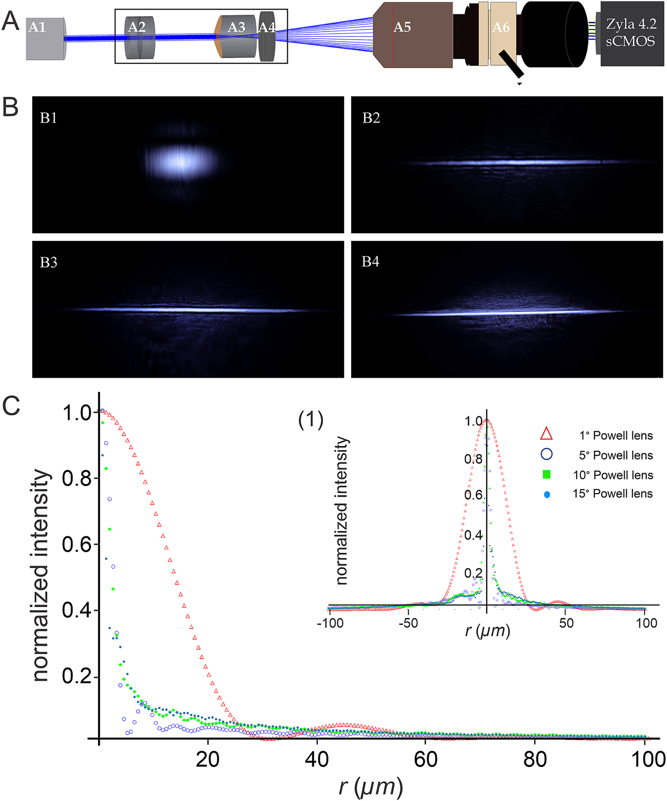
Effect of the fan angle of different Powell lenses on the intensity distribution of an incident Gaussian laser beam. (A) Experimental setup for measuring intensity distributions: (A1) 488 nm Sapphire laser with 200 mW power (Coherent Inc., Germany), (A2) Neutral Density Filters (NDFs, Thorlabs, USA), (A3) Powell lens with a fan angle of either 1°, 5°, 10°, or 15°, (A4) achromatic convex lens for guiding the altered beam into the entrance pupil of the detection objective without truncation, (A5) detection objective (Olympus XOL Fluor 4×, NA 0.28, WD: 29.25 mm, Japan), (A6) 3-position Trinocular Head U-TR30-2 (Olympus, Japan) with attached C-mount adapter connected to a Zyla 4.2 sCMOS camera (Andor, UK). (B) Transversal intensity distributions (XY plane) of Gaussian laser beams after passing through Powell lenses with different fan angles. (B1–B4) demonstrate the beam profiles altered by passing through Powell lenses of 1°, 5°, 10°, and 15°, respectively. (C) The 2D-beam distributions (related to the thinness of the light distribution along the Y-axis of reshaped laser beams depicted in (B)), were measured over a range of ±100 µm away from the beam waist. For better clarity and precision (C) only shows one-half of the intensity distribution. The Inlay (1) represents the entire profile.
The utilized light source is a 488 nm Sapphire laser with 200 mW power (Coherent Inc., Germany) providing a single mode output beam with Gaussian intensity distribution.
The incident laser beam width determined using the 86 % or 1/e ^ 2 encircling energy method is ∼700 µm and the beam exhibits a beam propagation factor of M 2 = 1.05.
The distance between the laser and the entrance pupil of the detecting objective (Olympus, 4X-NA:0.28, WD: 29.25 mm, Japan) was fixed at 500 mm. Image acquisition was performed using a Zyla 4.2 sCMOS camera manufactured by Andor (UK), featuring a resolution of 2,048 × 2,048 pixels. As the size of the camera chip is 13.312 mm × 13.312 mm the physical pixel size calculates to 6.5 µm × 6.5 µm. To prevent saturation, Neutral Density Filters (NDFs) from Thorlabs (USA) were employed.
Axial Conic-aspheric elements, such as Powell lenses, can directly modify the incident laser beam profile by changing the phase and amplitude along a specific axis. In Figure 1, B1–B4, we illustrate these alterations by sending a Gaussian laser beam through different Powell lenses with fan angles of 1°, 5°, 10°, and 15°. All Powell lenses used were made from N-BK7 and provided by Laserline, Canada.
Due to the specific optical characteristics of Powell lenses (e.g. the radius of curvature at the tip, the fan angle, and the refractive index of the material), the incident laser beam undergoes distinct optical phenomena, such as refraction and spherical aberration.
As a result, both the phase and amplitude of the beam undergo significant changes, leading to the reshaping of the beam. Notably, the Powell lens with the smallest fan angle (1°) transforms the incident symmetrical Gaussian beam into a quasi-elliptical beam with a subtle side shoulder parallel to the longer axis of the elliptical profile.
The refracted beam exhibits a pronounced divergence along the long axis, possibly being truncated by the edges of the lens, which is a common effect of small optical elements. This truncation can cause diffraction patterns that manifest in the form of side peaks or long spikes along the beam’s edges. With an increase of the fan angle, the profile of the output beam tends to approximate a narrow line resembling a light sheet along the propagation axis.
However, this transformation comes at the cost of introducing multiple side shoulders and an increase in the halo around the light sheet (Figure 1 B1–B4).
To further evaluate the results depicted in Figure 1 B1–B4 we measured the beam profiles along the y-axis (i.e. perpendicular to the laser line) (Figure 1-C). The radii were determined using the Full-Width-Half-Maximum (FWHM), the 86 % encircled energy, and the 95 % encircled energy methods (Table 1).
Measured radii of the beam profiles presented in Figure 1-F1 to F4 using FWHM, 86 % encircled energy, and 95 % encircled energy methods.
| Fan angle | 1° | 5° | 10° | 15° |
| Full-width half maximum (FWHM) | 27.72 µm | 5.06 µm | 4.24 µm | 3.2 µm |
| 86 % encircling energy | 43.2 µm | 7.6 µm | 11 µm | 13.4 µm |
| 95 % encircling energy | 91.2 µm | 19.8 µm | 34.9 µm | 51 µm |
If considering the FWHM approach, the 15° Powell lens provides the thinnest line along the XY plane at the observation point. However, looking at the beam radii obtained using the 86 % and 95 % approaches this presumed fact changes instantly.
To further clarify this matter, Table 2 compares the δ-ratios (defined here as the ratio of the beam radii obtained using 86 % or 95 % encircled energy and the radii obtained using the FWHM method, respectively) of the different Powell lenses.
Expansion ratio of radii determined by FWHM compared with values obtained using 86 % encircled energy, and 95 % encircled energy methods.
| Fan angle | 1° | 5° | 10° | 15° |
|
|
1.56 | 1.5 | 2.6 | 4.2 |
|
|
3.29 | 3.9 | 8.23 | 15.94 |
From the performed experiments it is evident that Powell lenses with a fan angle of less than 4° do not produce bright and thin lines with uniform intensity distribution as required in light sheet microscopy. Conversely, Powell lenses with a fan angle greater than 10° are also not suitable for applications such as high-precision precision 3D imaging, despite the fact that they can generate very thin lines in principle. This limitation is mostly due to their tendency to accumulate much power in side lobes and their high δ-ratios. In conclusion, Powell lenses with fan angles ranging from 5° to 10° seem to be most suitable for demanding imaging applications such as high-resolution light sheet microscopy if they are thoughtfully combined with further optical elements. In the result section we apply these findings to the design of a basic light sheet microscope with outstanding beam quality that can easily be assembled.
2.2 Sample preparation for microscopy (chicken embryos)
Fertilized white Lohmann chicken eggs (Schropper GmbH, Gloggnitz) were incubated at 37.6 °C and 60 % humidity. On the third day of embryonic development, the eggshells were gently cracked allowing access to the embryos, which were subsequently placed in sterile dishes for ex ovo incubation. The dishes were securely covered for further use. Chicken embryos were systematically collected at various stages of development, specifically on days 3, 4, 5, 6, and 7. Following collection, the embryos underwent a gentle rinse in phosphate-buffered saline (PBS) before being transferred into a solution of 4 % paraformaldehyde for fixation. They were kept in this solution until the clearing procedure began (Figure 2-A).
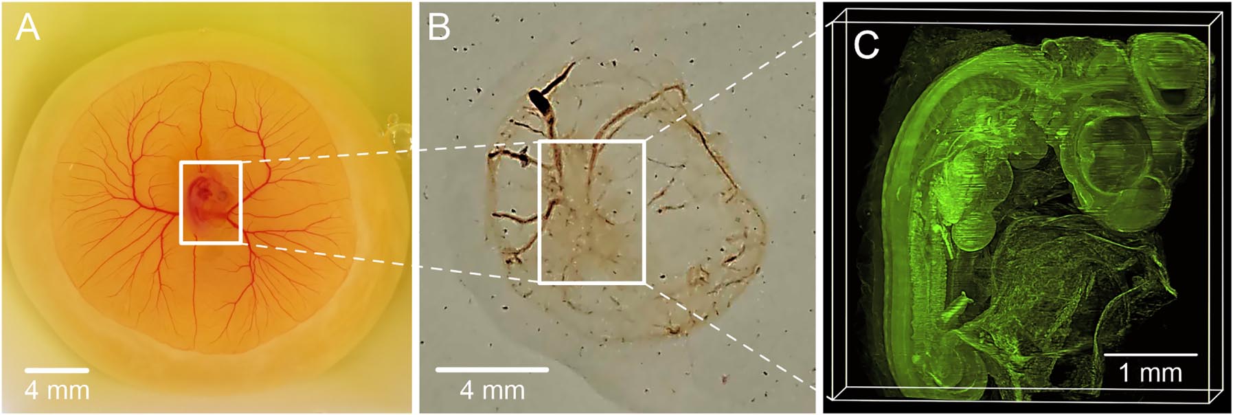
Clearing steps of a 4-day-old chick embryo, (A) the chick embryo is kept in a solution of 4 % paraformaldehyde for fixation, (B) Chemically cleared chick embryo, (C) reconstructed 3D-image of the chick embryo utilizing its autofluorescence signals captured through 970 images.
2.3 Sample clearing
The embryos were fixed in a 4 % solution of paraformaldehyde in phosphate-buffered saline (PBS) for a minimum of 24 h. Subsequently, the specimen underwent dehydration using a series of increasing concentrations of anhydrous tetrahydrofuran (THF). The successive concentration steps included 70 %, 80 %, 90 %, and 96 % THF in water, followed by two immersions in 100 % THF, each lasting between 8 and 16 h. THF utilized for the 100 % concentration steps was stored over a 3 Å molecular sieve mesh (Merck, Germany) to ensure the absence of traces of water. The dehydrated samples were then immersed in benzyl ether (DBE, Merck, Germany) for clearing, rendering them transparent within 24 h. The DBE solution was refreshed once after 8 h. Following clearing, the samples were kept at 4 °C in the clearing solution until imaging, with storage durations ranging from 3 days to 2 months. Prolonged storage led to a slight enhancement in transparency and intensity of the autofluorescence signal utilized for imaging as shown in Figure 2.
3 Results
3.1 Technical optimization of one axial meso-aspheric-based light sheet microscope
Previous studies with all details have highlighted the superior optical quality of light sheets generated by a system incorporating a Powell lens with a 5° angle in conjunction with two cylindrical lenses of specific structures, compared to a conventional setup comprising a cylindrical lens and a focusing unit [14], [15], [16], [17], [22]. Here we demonstrate that Powell lenses with fan angles in the range of 5°<α < 10°, improve the optical quality of a light sheet used for microscopy if combined with further meticulously chosen aspheric optical components.
In addition to our experimental studies, we applied Ansys-Zemax OpticStudio-2024 to model the effects of two different Powell lenses with fan angles of 5° and 7.5° on a laser beam emitting a 488 nm wavelength with a Gaussian distribution of approximately 700 µm width. A comparison of the results of both simulations was conducted in the absence of any further focusing lenses. as illustrated in Figure 3-D (D1 and D2). As evident from the figure, even a minute increase in the fan angle results in a longer bone-shaped beam, whereas the maximum intensity is always concentrated at the two far ends of the profile. Towards the middle, the intensity decreases gradually.
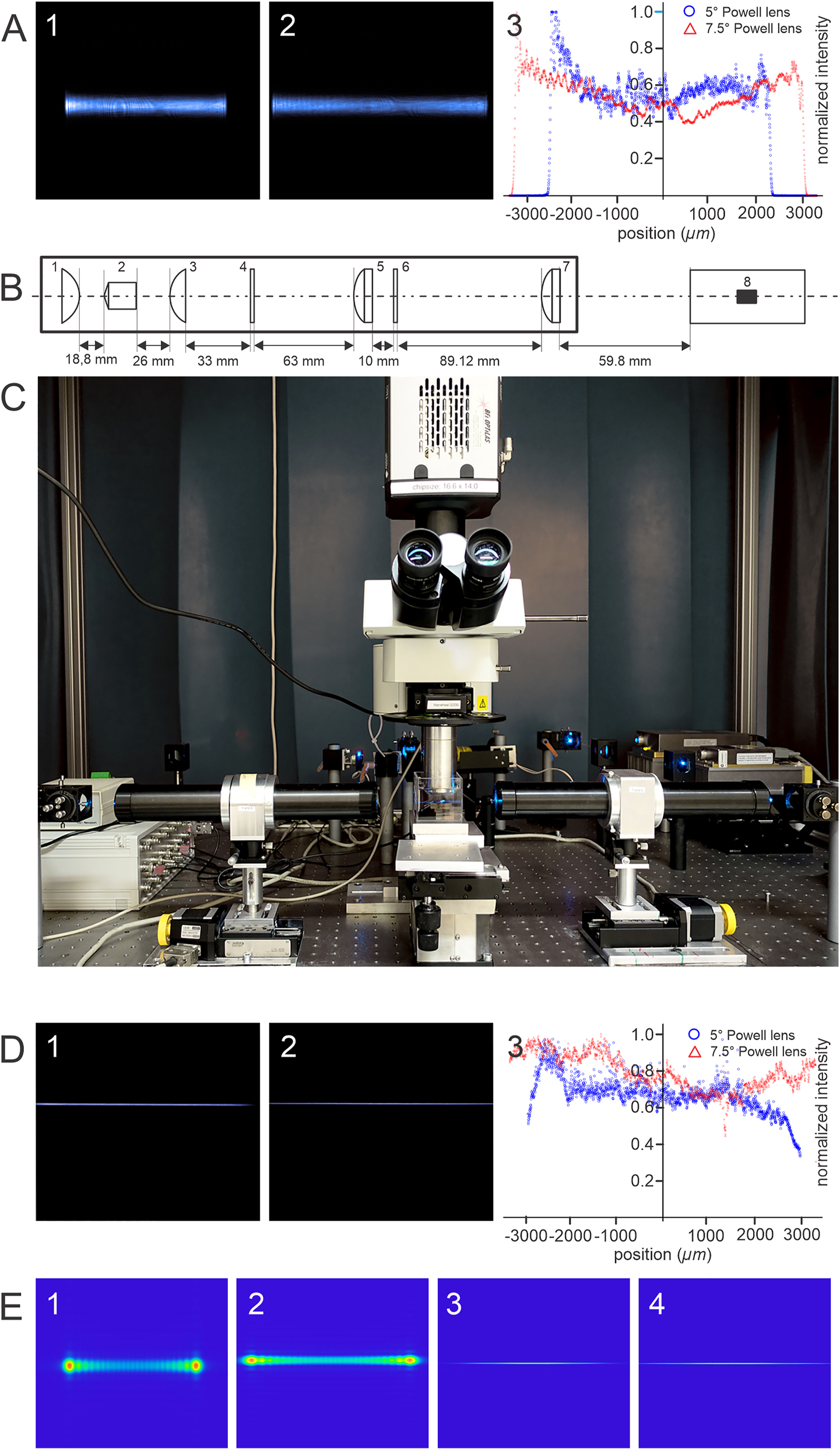
Simulated and experimental analysis of the effects of fan angle in a meso-aspheric based light sheet microscope. (A) Intensity distribution in the XY plane and along the X-axis. (A-1): XY-plane of the measured altered beam created by passing a Gaussian beam through a 5° Powell lens. For capturing the image D-1-4 the setup depicted in Figure 1-A-4 was used without the focusing lens. (A-2): XY-plane of the measured altered beam created by passing a Gaussian beam through a 7.5° Powell lens. (A-3) Comparison between the intensity distribution along the x-axis using Powell lenses of 5° and 7.5° fan angle. (B) Optical light sheet generator unit comprising: an aspheric condenser lens of +18 mm focal length (1). A Powel lens of 7.5° placed 18.8 mm away from the curved surface of the first lens (2). An aspheric condenser lens of +18 mm focal length is placed at 26 mm distance from the Powell lens (3). A soft aperture of 2 mm thickness is placed at 33 mm distance from the third lens (4). An achromatic-cylindrical lens of 75 mm focal distance placed at 63 mm distance from the soft aperture (5), A linear polarizer plane placed at 10 mm distance from the lens-5 (6), an achromatic-cylindrical lens of 75 mm for final focusing the altered light into an optimized light sheet (7). The waist of the thin light sheet is located at the center of the container where the sample is placed (8). (C) The photo of the setup comprising Sapphire laser (Coherent Inc.,/Germany) emitting 488 nm wavelength, mirrors, light sheet generator units, computer-controlled vertical and horizontal stages, corrected objective, sample container, and Neo 5.5 sCMOS camera (Andor, UK). (D) The light sheet generated by the system is shown in (B). (D-1) The measured light sheet profile at XY-Plane when a 5° Powel lens is used. (D-2) The measured light sheet profile at XY-Plane when a 7.5° Powel lens is used. (D-3) A comparison between the intensity distribution of the generated light sheets along the x-axis using 5° and 7.5° Powel lenses used in the system depicted in (B). (E) Simulated XY-plane intensity profiles of the altered Gaussian beam passing through 5° and 7.5° Powell lens using Ansys-Zemax OpticStudio-2024, respectively (1–2). The simulated XY-plane intensity profiles of the generated light sheet when Powell lenses of 5° and 7.5° are used in the system according to the design in (C) using Ansys-Zemax OpticStudio-2024, respectively (3–4).
For constructing a light-sheet generator that is suitable for fluorescence light-sheet microscopy both 5° and 7.5° Powell lenses appear to be viable options. The laser beam, akin to the setup depicted in Figure 1-A, is directed towards the Powell lenses, with the focusing lens (Figure 1-A4) removed.
To ensure the complete capture of the modified beams from both Powell lenses without any truncation occurring either at the entrance pupil of the objective or at the edges of the CCD chip, the detection objective is precisely positioned at a fixed location (refer to Figure 3 A-1 and A-2).
The intensity distribution in the bone-shaped beam produced by a 5° Powell lens exhibits pronounced fluctuations and less uniformity compared to a 7.5° Powell lens (Figure 3 A1–A3).
Hence, owing to the reduced presence of fluctuations and spikes in the spatial intensity distribution as well as an extended length of uniformity, selecting a Powell lens with a fan angle of 7.5° appears to be the best choice for designing a light sheet generator system.
The design of our light sheet generator is an optimization of one of our previously designed Meso-aspheric light sheet generator systems for microscopy [19]. Its optical elements are depicted schematically in Figure 3-B. The system comprises the following optical components:
Positive aspheric-condenser lens; Focal length: +18 mm, Material: Bk7, Conic factor: 1, Thickness: ∼10 mm, Diameter: 25 mm (Linos, Germany),
Powell lenses; Fan angle: 5° and 7.5°, Material: Bk7, Radius of curvature of the tip: ∼0.4 mm (Laserline, Canada),
Positive condenser aspheric lens of focal length +18 mm, similar to lens-1 (Linos, Germany),
Custom-made soft aperture (Linear apodizing density gradients with specific polynomial function filter (clear at the center, thickness: 2 mm, Diameter: 25 mm, (Reynard Co., USA),
Achromatic-cylinder lens of focal length: +75 mm, Surfaces: Toroidal, Radius of curvatures (rc): rc 1 = 43.48 mm, rc 2 = −32.43 mm, rc 3 = −113.9 mm, Materials: N-Bk7 and N-SF2, Diameter: 25 mm, Center thickness (CT): 10.88 mm (Thorlabs, USA),
Linear polarizer plate: Diameter: 25.4 mm, Thickness: 2 mm (Thorlabs, USA),
Focusing positive aspheric-cylinder lens of +75 mm focal length (the optical characteristics are similar to lens-5 (Thorlabs, USA).
An image of our setup equipped with a light sheet generator unit as described above is shown in Figure 3-C. According to our simulations performed with Ansys-Zemax OpticStudio-2024, the projected setup can generate a thin sheet of light either using a Powell lens of either 5° or 7.5° fan angle (Figure 3 E3 and E4).
However, as confirmed by our experimental findings described previously, the light sheet produced with a Powell lens of 7.5° exhibits a clearly superior optical quality (Figure 3 D1 and D2) as the intensity distribution along the x-axis of the light sheet generated by the setup employing a 7.5° Powell lens is quasi-uniform along all axes and the angle of divergence is improved compared to the system utilizing a 5° Powell lens. Furthermore, the axial resolution can be improved by a factor of at least 1.25.
Therefore, the combination of the optical components depicted in Figure 3-B is well suited for establishing an optimized static light sheet microscope that can be applied for imaging even very large samples. For smaller samples, the Powell lens in the light sheet generator unit (Figure 3-B(2) can be easily replaced in the setup by a 5° Powell lens or even smaller fan angle.
3.2 Imaging the development of chicken embryos using one axial meso-aspheric-based light sheet microscope
After chemical clearing with benzyl ether [23] we could visualize the anatomy of entire chicken embryos in different developmental stages ranging from day 3 to day 5 just by utilizing their autofluorescence (Figure 4 A1–B2).
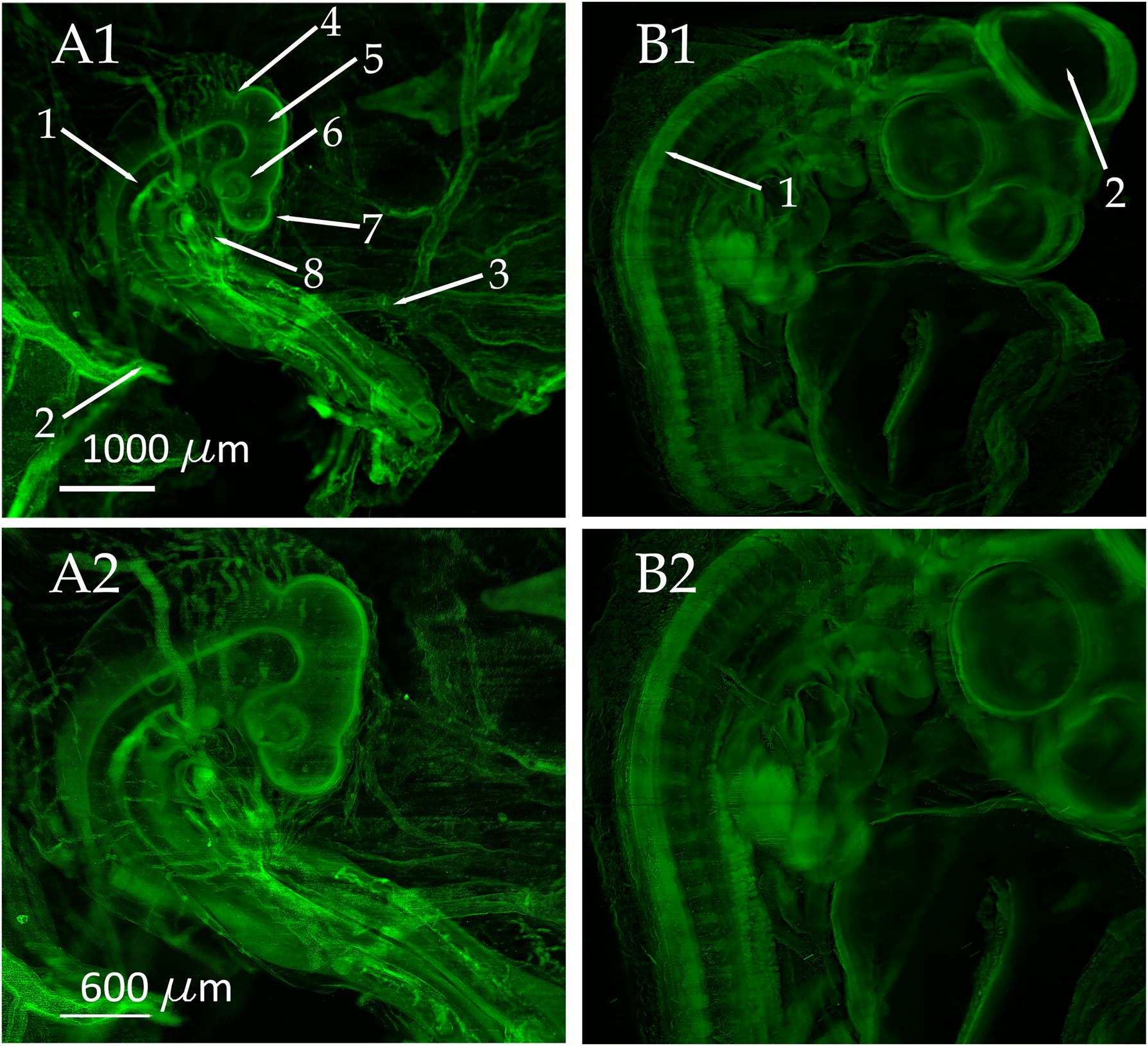
3D reconstructions of chicken embryos obtained with our optimized light sheet microscopy setup. For image recording a 2X objective (XL-Flour, NA 0.14, Olympus, Japan) and an Andor Neo 5.5 sCMOS camera (Andor, UK) was used. The objective was equipped with a custom-made modulator for compensating the refractive index mismatch. (A1 and A2) 3D reconstruction obtained from a 3-day-old chicken embryo. The MIP projections were computed from 679 single optical slices. Multiple anatomical details as the dorsal aorta (A1-1), the left omphalo-mesenteric artery (A1-2), the right omphalo-mesenteric (vitelline) artery (A1-3), isthmus (A1-4), mesencephalon (A1-5), optic cup (A1-6), diencephalon (A1-7), and heart (A1-8) can be clearly distinguished in the images. To enhance the visibility of fine details, image A2 is magnified by a factor of 1.67. (B1 and B2) MIP projections of a 5-day-old chicken embryo obtained from 607 optical slices. Additionally, to the anatomical structures visible in (A1 and A2), the neural tube (B1-1) and the Mesencephalon (B1-2) can clearly be seen on day 5. To enhance the visibility of fine details, image B2 is magnified by a factor of 1.67.
For the excitation of autofluorescence, we use a 488 nm sapphire laser (Coherent Inc., Germany). For bi-directional illumination from two opposing sides, a 50 % beam splitter is used to split the laser beam into two arms of the same intensity. Both beams are then fed into two identical light sheet generator units situated at alternating sides of the specimen chamber made from optical glass (Hellma, Germany). The specimen chamber is filled with benzyl ether, which approximately matches the refractive index of protein (r = 1.562) (Figure 3-C). The detection system that is arranged perpendicular to the illumination system is equipped with an air objective (Olympus FLUAR 2× or 4×, Olympus, Japan) and a custom-designed modulator for compensating the refractive index disparity between air and the sample immersion medium (Figure 3-C). The objective is mounted to a 3-position Trinocular Microscope Head (Leica, Germany) equipped with a tube lens. An Andor Neo 5.5 sCMOS camera (Andor, UK) is attached to the Trinocular microscope head via a standard C-mount adapter.
The sample can be scanned through the static light sheet along the optical axis of the microscope by a computer-controlled elevation stage boasting an adjustment precision of about 100 nm (Es-100, PI-Micos, Germany). In order to illuminate the specimens with a light sheet of minimal width the x-position of the two light-sheet generator units can be precisely adjusted by two computer-controlled linear stages (PI-Micos, Germany). Controlling of the entire setup, and automatic capturing of image stacks while the sample is moving stepwise through the light sheet is performed by custom-made software.
Subsequent image processing (deconvolution, removal of stripe artifacts) and 3D reconstruction are done using the NeuroDeblur deconvolution software (MBF Bioscience, USA) and Amira 2020.2 (Thermo Scientific™, USA).
We recorded and reconstructed stacks of images from chicken embryos in developmental stages between 3 and 7 days (Figures 4 and 5, Movies 1 to 5 in the supplemental information). Specific biological details such as the dorsal aorta, left omphalo-mesenteric artery, right omphalo-mesenteric (vitelline) artery, isthmus, optic cup, mesencephalon, diencephalon, and telencephalon can be seen in the images obtained at day 3 (Figure 4 A1 and A2). Further important anatomical structures such as the neural tube and the developing mesencephalon become apparent on day 5 (Figure 4 B1 and B2).
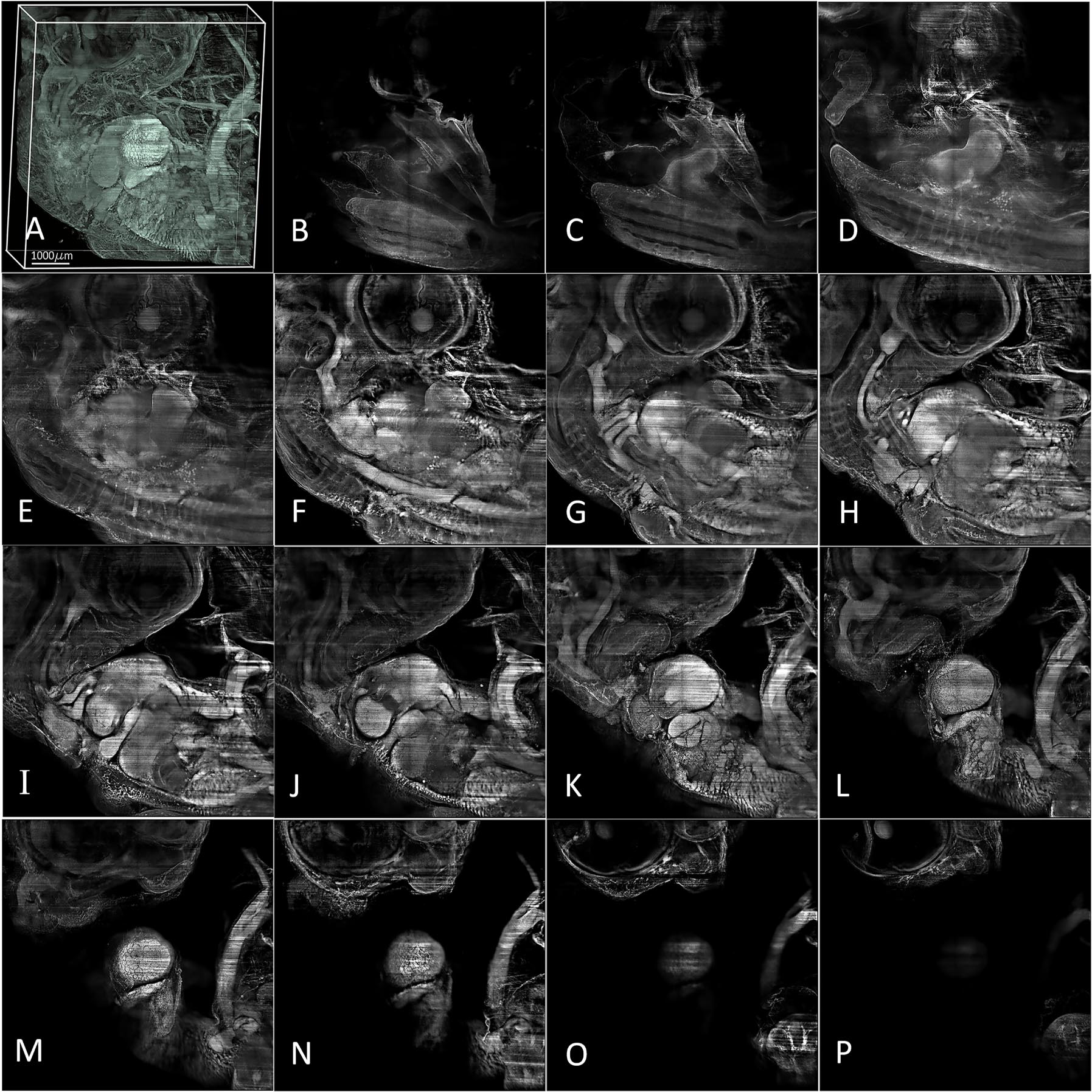
A 3D image of a 7-day-old chick embryo was reconstructed using 1,350 images with a 2 µm interval captured by a 2X objective (NA: 0.14, Olympus/Japan) equipped with a modulator to compensate for refractive index mismatch. Imaging was performed with a Neo 5.5 sCMOS camera (Andor, UK) and processed using Amira software. Single images of various planes within the sample were obtained using thin light sheet illumination, with intervals of 100 µm. The images range from B (representing 100 µm from the deepest part) to P (representing the upper part of the image) over a distance of 1,500 µm.
A further z-stack with 1,350 frames taken in intervals of 2 µm was captured from a 7-day-old embryo. Expectedly, the 3D reconstructions show the most anatomical details (Figure 5) and provide intricate insights into the progress of embryological development. In summary, our imaging results provide evidence that our light-sheet microscopy design can be a powerful tool for embryological studies.
4 Discussion
We investigated the effect of four Powell lenses with different fan angles (1°, 5°, 10°, and 15°) on a symmetrical laser beam with Gaussian intensity distribution by means of beam profile measurements and computer simulations using Zemax. Our findings reveal that Powell lenses with fan angles between 5° and 10° are highly useful to improve the optical characteristics, such as its uniformity and the length of the Rayleigh range, of a thin light sheet. Moreover, when combined with further aspheric optical components these aspheric lenses can notably improve the performance of light-sheet generators used for light-sheet fluorescence microscopy. Our findings indicate that Powell lenses with fan angles between 5° and 7.5° are the best choice for this purpose. Specifically, when imaging large samples, a 7.5° Powell lens is preferred, due to the higher uniformity and the lower intensity fluctuations of the generated light sheet. High consistency and stability of the light sheet are both paramount in the context of 3D imaging microscopy. Based on our findings, we designed a light-sheet microscope that incorporates multiple aspheric lenses in combination with an axial Meso-Aspheric-lens. We accessed the performance and validity of our proposed setup by applying it to the imaging of chicken embryos between 3 and 7 days of age. The obtained images reveal even delicate details of the embryos’ inner anatomy, underscoring the potential of this system as a powerful tool in embryological studies.
To enhance clarity and level of detail, the raw images underwent deconvolution using NeuroDeblur software (MBF Bioscience, USA) (Figure x A-B). NeuroDeblur facilitates straightforward deconvolution without necessitating PSF measurements by employing a computed PSF optimized specifically for light sheet microscopy. In light-sheet microscopy recordings of chemically cleared samples, stripe artifacts often arise due to shadows that are caused by small particles remaining uncleared within the samples. It should be noted, NeuroDeblur also provides a feature to effectively mitigate these stripe artifacts as can be seen in Figure 6A–C. However, for the purpose of testing and characterizing our microscope design, we opted to utilize the non-destriped data as they align more closely with the original.

Single image of 7-days old Chicken emberyo captured by a 2X objective (NA: 0.14, Olympus/Japan) equipped with a modulator to compensate for refractive index mismatch, (A) raw data, (B) deconvolved data using NeuroDeblur software (MBF Bioscience, USA), (C) destriped after performing deconvolution using NeuroDeblur software.
In the end, it is essential to clarify that the findings presented herein are confined to the outcomes achievable through the utilization of a singular axial-conic-aspheric lens, such as a Powell lens. It is pertinent to note that the amalgamation of two or more such optical elements holds promise for further enhancements, thus warranting future investigation and exploration.
5 Conclusions
In conclusion, our study demonstrates the efficacy of axial-conical lenses (Powell lenses) with fan angles between 5° and 7.5° in creating thin light sheets with exceptional optical properties. The design we propose for a basic light sheet generator for light-sheet microscopy facilitates high-resolution 3D reconstructions of chicken embryos at various stages of embryological development.
Funding source: Vienna Science and Technology Fund (WWTF)
Award Identifier / Grant number: NXT22-001
Funding source: Austria Wirtschaftsservice (AWS)
Award Identifier / Grant number: AWS: P2403385
Acknowledgments
The authors thank the Austria Wirtschaftsservice (AWS) and Vienna Science and Technology Fund (WWTF) for their support.
-
Research ethics: Due to the age and conditions of the chicken embryos, no ethical approval is required.
-
Author contributions: All authors have accepted responsibility for the entire content of this manuscript and approved its submission.
-
Competing interests: Authors state no conflict of interest.
-
Research funding: This research is partially funded by the Austria Wirtschaftsservice (AWS) and Vienna Science and Technology Fund (WWTF) through two projects AWS: P2403385 and WWTF: NXT22-001, respectively.
-
Data availability: Not applicable.
References
[1] F. M. Dickey, “Laser beam shaping,” Opt. Photonics News, vol. 14, no. 4, pp. 30–35, 2003. https://doi.org/10.1364/opn.14.4.000030.Search in Google Scholar
[2] F. Homburg, O. Hauschild, D. Kubacki, and L. Vitalij, “Efficient beam shaping for high-power laser applications,” [Online], 2007. Available at: www.laser-journal.de.10.1117/12.668004Search in Google Scholar
[3] M. Singh, Beam Shaping by Optical Map Transforms, Cities of Joensuu and Kuopio, University of Eastern Finland, 2012.Search in Google Scholar
[4] A. Laskin and V. Laskin, “Refractive field mapping beam shaping optics: important features for a right choice,” in 29th Int. Congr. Appl. Lasers Electro-Optics, ICALEO 2010 – Congr. Proc., vol. 103, 2010, pp. 1181–1189.10.2351/1.5061957Search in Google Scholar
[5] V. Peet, “Laser beam shaping by conical refraction in biaxial crystals,” Opt. Model Des. II, vol. 8429, no. 4, 2012, https://doi.org/10.1117/12.922201.Search in Google Scholar
[6] F. M. Dickey and S. Holswade, Laser Beam Shaping: Theory and Techniques, New York, Taylor & Francis, 2009.Search in Google Scholar
[7] S. Saghafi, et al.., “Reshaping a multimode laser beam into a constructed Gaussian beam for generating a thin light sheet,” J. Biophotonics, vol. 11, no. 6, pp. 1–9, 2018. https://doi.org/10.1002/jbio.201700213.Search in Google Scholar PubMed
[8] M. Zhang, X. Liu, L. Guo, L. Liu, and Y. Cai, “Partially coherent flat-topped beam generated by an axicon,” Appl. Sci., vol. 9, no. 7, pp. 1–10, 2019. https://doi.org/10.3390/APP9071499.Search in Google Scholar
[9] J. Mayer, A. Robert-Moreno, J. Sharpe, and J. Swoger, “Attenuation artifacts in light sheet fluorescence microscopy corrected by OPTiSPIM,” Light: Sci. Appl., vol. 7, no. 1, pp. 1–13, 2018. https://doi.org/10.1038/s41377-018-0068-z.Search in Google Scholar PubMed PubMed Central
[10] S. Saghafi, et al.., “Outlook on optimizing ultramicroscopy imaging technique through optical characterization,” Microsc. Res. Tech., vol. 81, no. 9, pp. 929–935, 2018. https://doi.org/10.1002/jemt.22815.Search in Google Scholar PubMed
[11] V. Ntziachristos, “Going deeper than microscopy: the optical imaging Frontier in biology,” Nat. Methods, vol. 7, no. 6, pp. 603–614, 2010. https://doi.org/10.1038/nmeth.1483.Search in Google Scholar PubMed
[12] L. M. . Soroko, Meso-Optics : Foundations and Applications, Singapour, World Scientific, 1996.10.1142/9789812796349Search in Google Scholar
[13] S. Saghafi, et al.., “Engineering a better light sheet in an axicon‐based system using a flattened,” J. Biophotonics, vol. 15, no. 6, pp. 1–16, 2022. https://doi.org/10.1002/jbio.202100342.Search in Google Scholar PubMed PubMed Central
[14] S. Saghafi, K. Becker, C. Hahn, and H.-U. Dodt, “3D-ultramicroscopy utilizing aspheric optics,” J. Biophotonics, vol. 7, nos. 1–2, pp. 117–125, 2014, https://doi.org/10.1002/jbio.201300048.Search in Google Scholar PubMed
[15] M. Pende, et al.., “High-resolution ultramicroscopy of the developing and adult nervous system in optically cleared Drosophila melanogaster,” Nat. Commun., vol. 9, no. 1, pp. 1–12, 2018. https://doi.org/10.1038/s41467-018-07192-z.Search in Google Scholar PubMed PubMed Central
[16] C. Hahn, et al.., “High-resolution imaging of fluorescent whole mouse brains using stabilized organic media (sDISCO),” J. Biophotonics, vol. 12, no. 8, pp. 1–10, 2019. https://doi.org/10.1002/jbio.201800368.Search in Google Scholar PubMed
[17] I. Sabdyusheva Litschauer, et al.., “3D histopathology of human tumors by fast clearing and ultramicroscopy,” Sci. Rep., vol. 10, no. 1, pp. 1–16, 2020. https://doi.org/10.1038/s41598-020-71737-w.Search in Google Scholar PubMed PubMed Central
[18] L. Kramoreva, E. Petrova, and J. Razhko, “Quasi – nondiffractive beams for OCT – visualization : theoretical and experimental investigations,” in Theor. Exp. Investig. Sel. Top. Opt. Coherence Tomogr. Dr. Gangjun Liu [Online], 2012. Available at: http://www.intechopen.com/books/selected-topics-in-optical-coherence-tomography/quasi-nondiffractive-beams-for-oct-visualization-theoretical-and-experimental-investigations.10.5772/31162Search in Google Scholar
[19] S. Saghafi, et al.., “Outlook on optimizing ultramicroscopy imaging technique through optical characterization,” MRT, vol. 81, pp. 929–935, 2016.10.1002/jemt.22815Search in Google Scholar PubMed
[20] M. Haouas, B. Chebbi, and I. Golub, “Extension of the span and optimization of the optical ‘magic carpet’: generation of a wide quasi-nondiffracting light sheet,” J. Opt. Soc. Am. A, vol. 36, no. 1, pp. 124–131, 2019. https://doi.org/10.1364/JOSAA.36.000124.Search in Google Scholar PubMed
[21] K. Chen, W. Song, L. Han, and K. Bizheva, “Powell lens-based line-field spectral domain optical coherence tomography system for cellular resolution imaging of biological tissue,” Biomed. Opt. Express, vol. 14, no. 5, pp. 2003–2014, 2023. https://doi.org/10.1364/BOE.486980.Search in Google Scholar PubMed PubMed Central
[22] S. Saghafi, K. Becker, N. Jährling, and C. Hahn, Chapter 12 Ultramicroscopy of Nerve Fibers and Neurons : Fine-Tuning the Light Sheets, Berlin/Heidelberg, Springer, 2017.Search in Google Scholar
[23] K. Becker, N. Jährling, S. Saghafi, R. Weiler, and H.-U. Dodt, “Chemical clearing and dehydration of GFP expressing mouse brains,” PLoS One, vol. 7, no. 3, pp. 1–6, 2012. https://doi.org/10.1371/journal.pone.0033916.Search in Google Scholar PubMed PubMed Central
© 2024 the author(s), published by De Gruyter on behalf of Thoss Media
This work is licensed under the Creative Commons Attribution 4.0 International License.
Articles in the same Issue
- Frontmatter
- Editorials
- Empowering the Microscopy Community: Welcome to the Inaugural Issue of Methods in Microscopy
- Embracing innovation in microscopy
- News
- Microscopy Community News
- Special Issue: Volume Microscopy Across Scales
- View
- Array tomography: trails to discovery
- Tutorial
- Quantification of collective signalling in time-lapse microscopy images
- Research Articles
- A systematic approach of vitrification by high pressure freezing
- FAST-EM array tomography: a workflow for multibeam volume electron microscopy
- Converting a symmetrical Gaussian beam into a thin tunable light sheet
- Serial block-face scanning electron microscopy of adherent cells on thin plastic substrate
- How to increase freeze-substitution and electron microscopy embedding reliability