Experimental investigation and thermodynamic analysis of TiC–Fe cermets with Mo additions
-
 ,
,

Abstract
In this study, the effects of Mo additions on the microstructure, hardness and bending strength of TiC–Fe cermets manufactured by spark plasma sintering were investigated by scanning electron microscopy, X-ray diffraction and mechanical properties tests. Thermodynamic calculations were utilized to analyze the evolution of the microstructure. The results show that the conventional core/rim structure was not formed during the solid-phase sintering of TiC–Fe cermets. The heat-treatment process and reasonable Mo addition can effectively enhance the overall performance of the alloys. With the addition of minor Mo, the hardness of the sintered cermets improved significantly, which was attributed to the solid solution strengthening mechanism of Mo in Fe binder. However, excessive Mo exceeded the solubility range of Fe binder and precipitated in the form of M 6C and Mo2C phases, which damaged the bending strength of the heat-treated cermets.
1 Introduction
Metal matrix composites (MMCs) have been considered as promising materials for tools, wear-resistant parts, extrusion dies and punches, as well as components for surface finishing, high-speed milling, and machining of both carbon and stainless steels, due to their excellent performance, such as high strength, high hardness and good thermal stability. 1 , 2 , 3 In MMCs, the hard reinforcement particles provide the carrying capacity under external load, and the metal matrix is responsible for plastic deformation. 4 The interfacial bonding between the hard particles and the metal matrix is one of the most crucial factors that determine the toughness and strength of MMCs. 5 Significantly, a major drawback of TiC–Fe cermets is attributed to embrittlement introduced by the poor wettability of Fe binder on the TiC ceramic phase. 6 Several studies have reported that Mo is an indispensable metal for the fabrication of TiC-based cermets. This is because Mo precipitates on the surface of ceramic-phase grains to form rim structures during liquid phase sintering, which improves the wettability of the metallic binder phase in the ceramic phase. 7 , 8 , 9 , 10
In the liquid phase sintering process, refractory metals including Mo, Cr, W etc., promote the formation of core/rim structures via a dissolution and precipitation mechanism, which has been considered as a typical feature of TiC-based cermets. 11 , 12 , 13 Nevertheless, hot pressing (HP), hot isostatic pressing (HIP) and spark plasma sintering (SPS) techniques can realize the consolidation of TiC-based cermets only through solid-state sintering. 14 , 15 , 16 Whether the TiC–Fe–Mo alloys sintered by HP, HIP and SPS form a core/rim structure has not yet been definitively reported.
The microstructural evolution of TiC–Fe cermets involves complex thermodynamic and kinetic phenomena. Several factors are known to be associated with the microstructure and properties of cermets, such as alloy composition, sintering temperature and heat treatment process. 17 All these factors can be varied in numerous combinations via experimental trials. The CALPHAD (CALculation of PHAse Diagram) method has been demonstrated to be an efficient auxiliary tool, which can be used to calculate phase equilibria and thermodynamic properties. 18 , 19 , 20
In the present work, a hybrid approach of key experiments and thermodynamic calculations was employed to fundamentally understand the effect of different Mo contents on the microstructure, hardness and bending strength of SPS-prepared TiC–Fe cermets.
2 Experimental procedure
TiC (≥99.5 %, 6–10 μm), Fe (≥99.9 %, ∼3 μm), Mo (≥99.95 %, ∼3 μm) and graphite (≥99.95 %, ∼3 μm) were selected as starting materials, as shown in Figure 1. Table 1 summarizes the powder compositions used in the present work. The specimens were fabricated by conventional powder metallurgical technology. The powders were mixed in a planetary ball mill with tetrafluoroethylene tanks and ZrO2 balls at 300 r/min for 5 h. Sufficient alcohol was used as the dispersion medium, and the alcohol completely covered the powder to avoid oxidation. The ball milled slurry was placed in an 80 °C oven until it was completely dry and then passed through a 150 mesh screen. The composite powders were packed in graphite die with an inner diameter of 20 mm and densified in an SPS furnace (LABOX-350, Sinterland, Japan). The densification process was conducted at 1020 °C for 10 min in the vacuum condition with a heating rate of 60 K min−1 and pressure of 40 MPa. The sintered samples were then processed by this heat treatment: quenching at 1000 °C for 15 min and tempering at 200 °C for 1 h. The sintered and heat-treated cermets with dimensions of ∼20 mm in diameter and ∼4 mm in height were cut, ground and polished with diamond sand papers and diamond paste for further measurements.
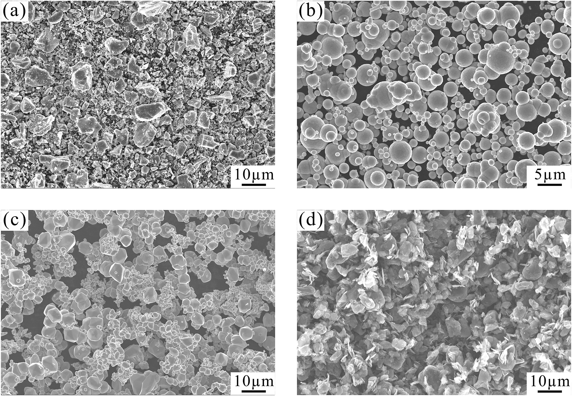
SEM micrographs of raw materials: (a) TiC powders, (b) Fe powders, (c) Mo powders, and (d) graphite powders.
Nominal compositions of specimens.
| Sample no. | Fe (wt.%) | TiC (wt.%) | Mo (wt.%) | C (wt.%) |
|---|---|---|---|---|
| 1 | Balance | 20 | 0 | 1 |
| 2 | Balance | 20 | 2 | 1 |
| 3 | Balance | 20 | 4 | 1 |
| 4 | Balance | 20 | 6 | 1 |
The density of the samples was measured by the Archimedes’ immersion method in water and the relative density was calculated based on the theoretical density. X-ray diffraction (XRD, Cu-Kα radiation, Smartlab, Rigaku, Japan) was used to analyze the phase constitution of the samples. Scanning electron microscopy (SEM, Sigma, Zeiss, Germany) equipped with an energy dispersive spectrometer (EDS) was utilized to evaluate the microstructure and phase composition. The hardness of the sample was measured by a Rockwell hardness tester under a load of 150 kg and a dwell time of 10 s. The bending strength was measured using a mechanical performance testing machine (IBTC-5000, CARE Measurement & Control Co., Ltd., P.R. China). Three-point bend testing was conducted on samples of 3 mm (width) × 3 mm (height) × 16 mm (length) under a loading speed of 0.5 mm min−1 and span of 12 mm. Density, hardness, and bending strength were averaged over more than five results.
Based on the established thermodynamic data, 18 the vertical section, phase composition and microstructural evolution of the alloy system were calculated by using Thermo-Calc software 21 for further analysis of the sintered and heat-treated TiC–Fe–Mo alloys.
3 Results and discussion
3.1 Phase characterization and microstructure analysis
The XRD patterns of the samples after sintering and heat-treatment are shown in Figure 2. TiC and Fe peaks were clearly determined in each sample, which suggested that there was no significant phase transition in the milling and sintering processes. The diffraction peaks of Fe in the sintered cermets presented a sharp morphology, which indicated that the binder was present as the phase α-Fe. In addition, the diffraction peaks of Fe in the heat-treated cermets were clearly broadened, which could be attributed to the martensite phase transformation of α-Fe during water quenching. A characteristic diffraction peak can be detected at 39.4° for the heat-treated cermet with the addition of 6.0 wt.% Mo, which was identified as the M 6C or Mo2C phase. This was because excess Mo cannot be dissolved into Fe binder and reacted with Fe and C to form M 6C.
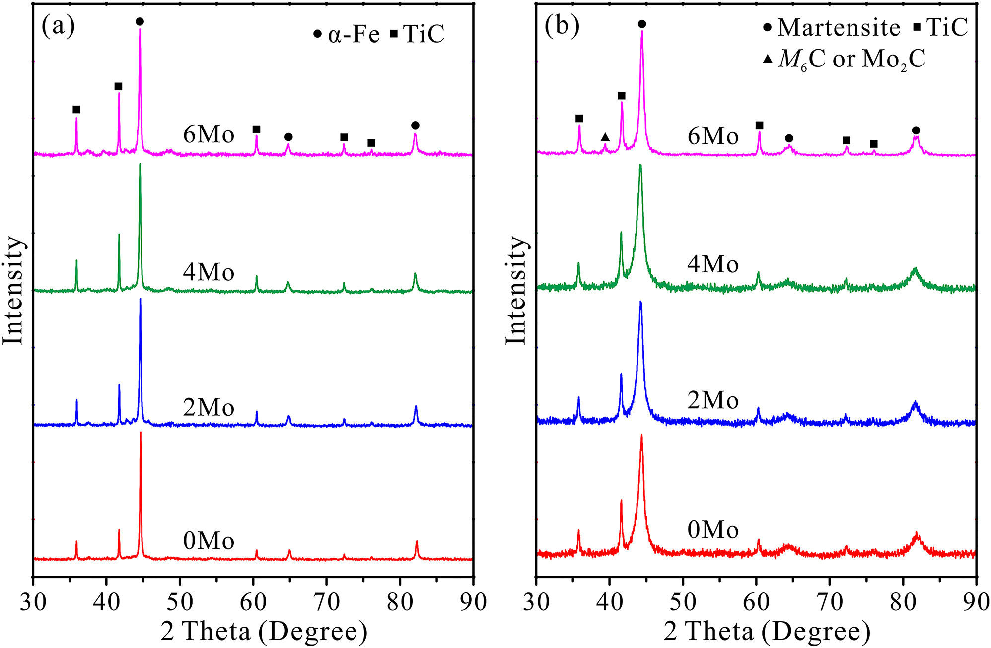
XRD patterns of patterns of (a) sintered TiC–Fe cermets and (b) heat-treated cermets.
SEM micrographs of sintered cermets with varying Mo contents are illustrated in Figure 3, in which the dark grey phase denotes the TiC-based hard phase particles that were independently distributed. The mid-grey binder phase permeated between the hard phase particles. Moreover, the granular hard phase was continuously wrapped in this binder phase. During the sintering in vacuum at 1020 °C, the Fe, Mo and graphite powders formed the binder phase by solid solution. The TiC hard particles in the sintered alloys showed angular and polygonal shape, and their grain size distribution was similar to the original powders, which are unlike those of similar conventional cermets prepared using the liquid sintering method. Due to solid phase sintering in the SPS process, Mo and TiC particles cannot undergo the solution-precipitation process, 12 so the core/rim structures were not formed and a large amount of small granular TiC particles remained in the TiC–Fe cermets. In the sintered cermet with 0 wt.% Mo as shown in Figure 3a, the black graphite phase can be observed, which may damage the mechanical properties of the cermets. With 2.0 wt.% Mo powder, the free carbon disappeared. With the Mo addition further increased, light-grey phase began to appear. In the sample with 6 wt.% Mo as shown in Figure 3d, the new phases can be clearly seen, consisting of a light-grey phase and a white phase. The light-grey phase accounted for the larger fraction of the volume, and the white phase accounted for the smaller fraction, in which the white phase was completely wrapped by the light-grey phase. Combined with the XRD results, these two phases should contain the intermediate compound M 6C or Mo2C. On the whole, there were no obvious holes in any sintered cermets, and dense samples can be obtained by SPS.
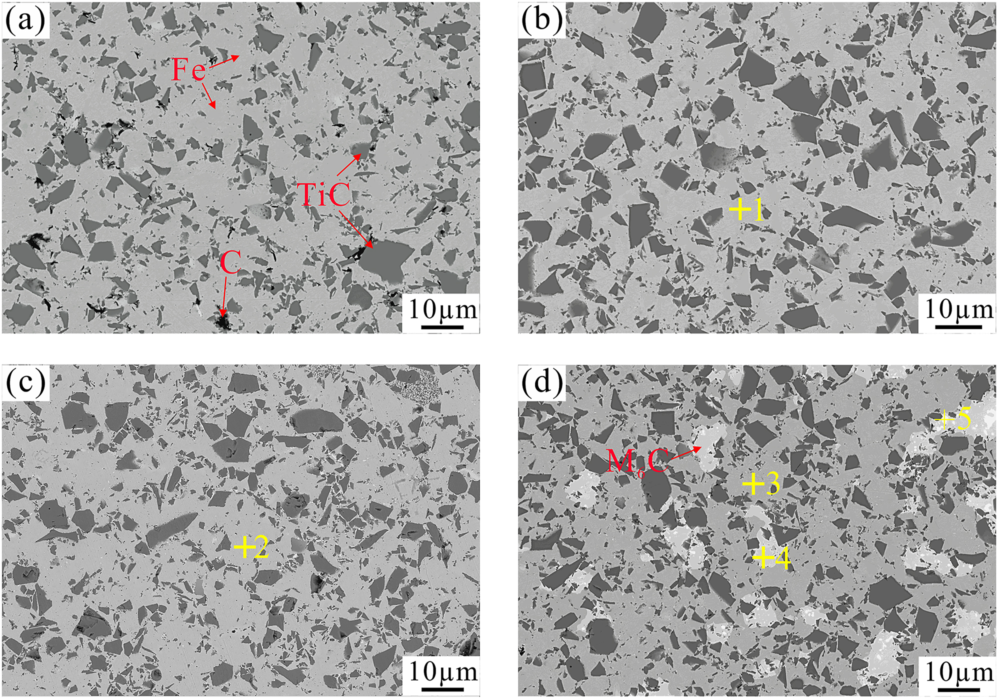
SEM images of the sintered TiC–Fe cermets with different Mo additions: (a) 0 wt.% Mo, (b) 2.0 wt.% Mo, (c) 4.0 wt.% Mo, and (d) 6.0 wt.% Mo.
Figure 4 presents SEM images of the heat-treated cermets with varying Mo contents. As can be seen in Figure 4a, the black graphite phase disappeared in the sample with 0 wt.% Mo. It can be inferred that the free carbon was completely dissolved into the tempered martensite phase. With the increasing Mo addition, the compound phases also gradually appeared in the heat-treated samples, which was consistent with the sintered samples. It is worth noting that the compound phases transformed into a lamellar microstructure composed of light-grey phase and white phase. This should be due to the solid solution of intermediate compounds at high temperature (1000 °C) and the decomposition and precipitation of phases at low temperature (200 °C).
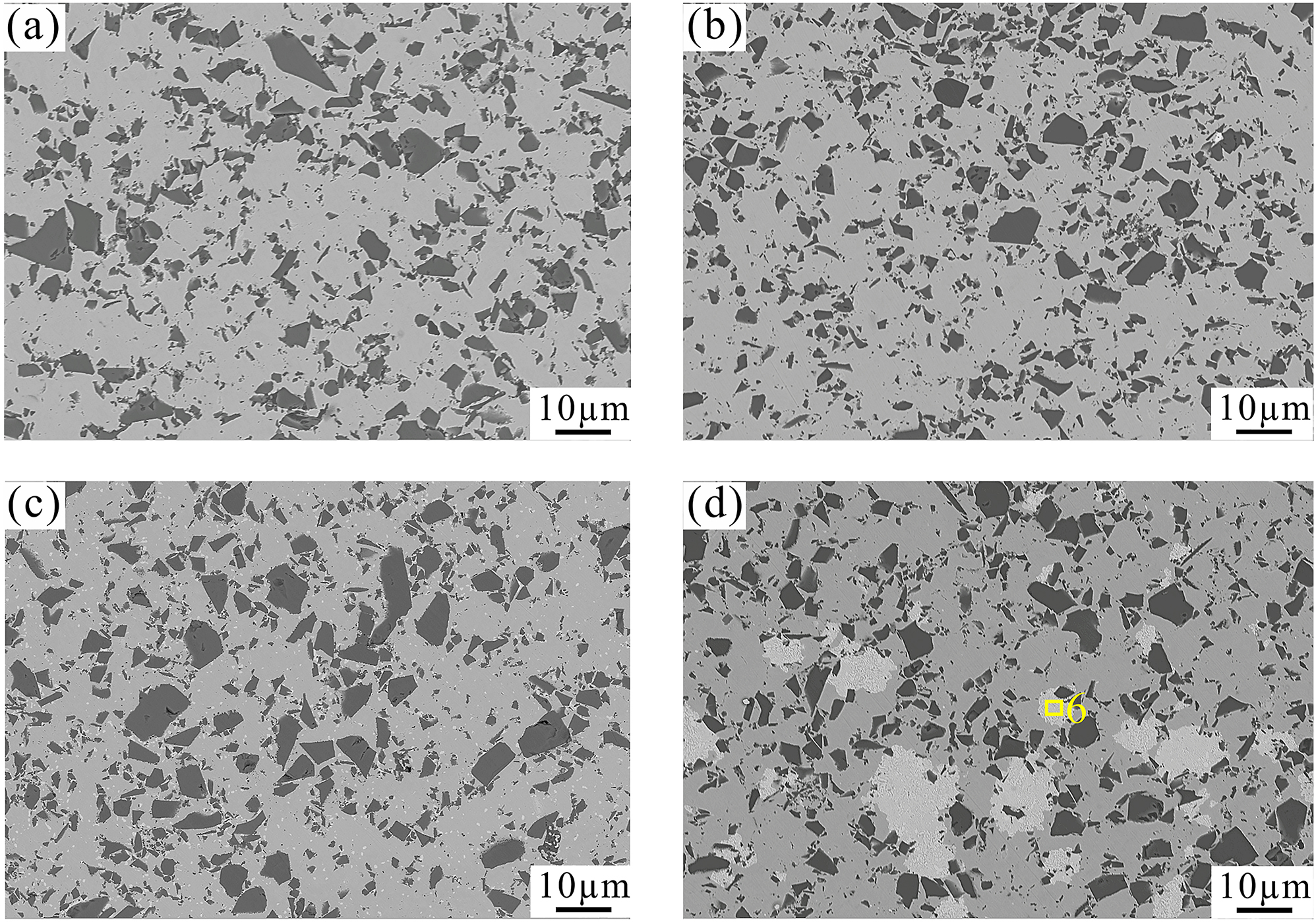
SEM images of the heat-treated TiC–Fe cermets with different Mo additions: (a) 0 wt.% Mo, (b) 2.0 wt.% Mo, (c) 4.0 wt.% Mo, and (d) 6.0 wt.% Mo.
3.2 EDS analysis and thermodynamic calculation
Figure 5 shows the EDS data of the TiC–Fe cermets. The composition of the metal binder in the sample sintered with 2.0 wt.% Mo was identified as 90.7Fe-2.0Mo-1.0Ti-6.3C, which demonstrated that Mo was mainly dissolved into Fe and became a solid solution strengthening element of the binder phase. With the Mo content increased to 4.0 wt.%, the composition of the Fe binder was adjusted to 90.4Fe-2.6Mo-1.1Ti-5.9C. It can be inferred that the solid solution content of Mo in Fe further increased, and meanwhile the excess Mo exceeded the solubility range of the metal binder and precipitated in the form of intermediate compounds. Due to the limited particle size of the compounds in this sample, the specific composition cannot be accurately detected in the present work. When the Mo content further increased to 6.0 wt.%, the compositions of Fe binder, light-grey phase and white phase were presented as 91.7Fe-2.6Mo-1.0Ti-4.7C, 54.1Fe-34.5Mo-0.9Ti-10.5C and 5.7Fe-80.6Mo-13.7C, respectively. According to the Fe–Mo–Ti–C phase diagram and EDS results, the light-grey and white phases can be determined as M 6C and Mo2C. In addition, the lamellar microstructure in the heat-treated cermet with 6.0 wt.% Mo was identified as the average composition of 52.8Fe-37.6Mo-0.7Ti-8.9C, which should be composed of the M 6C and Mo2C phases. For the reason that the volume fraction of Mo2C only accounted for a very small proportion, the composition of the lamellar microstructure was similar to that of the M 6C phase.
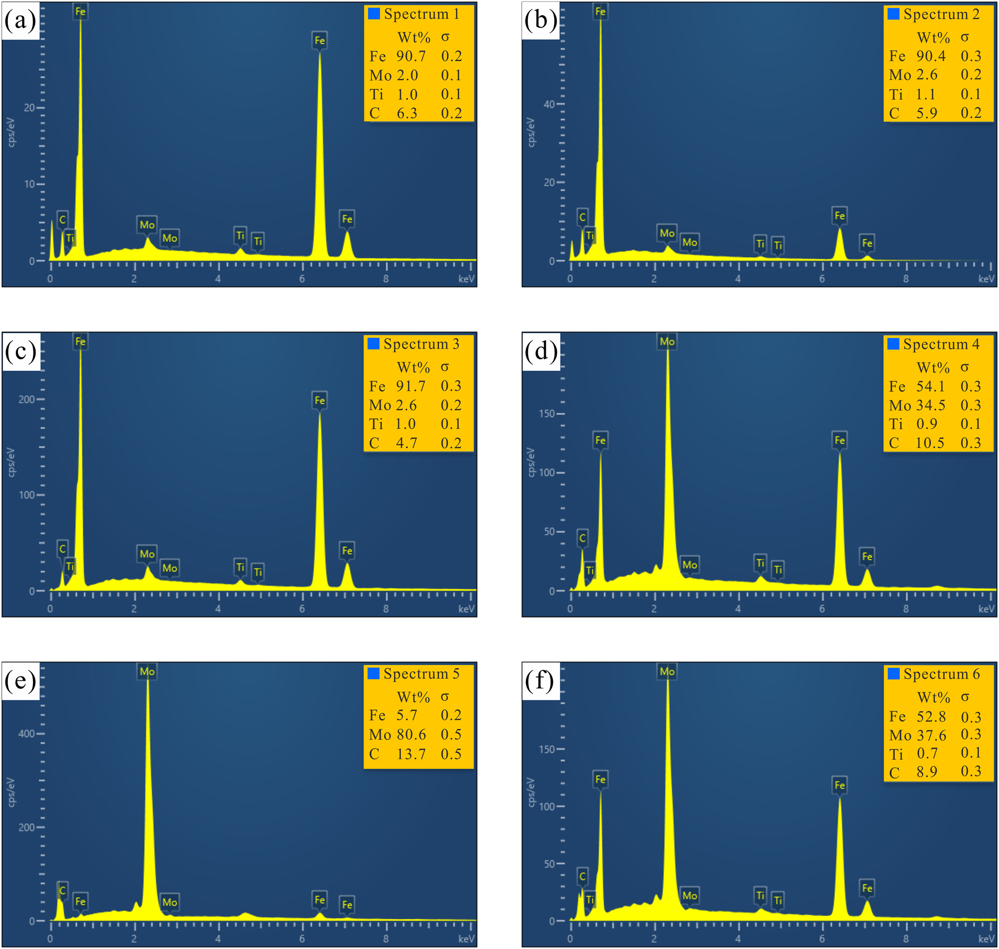
In order to further verify the absence of the conventional core–rim structure in the TiC–Fe cermets, the elemental distribution determined by EDS linear scanning across a hard particle of the heat-treated sample with 4.0 wt.% Mo is presented in Figure 6. The Mo content in the rim of the TiC hard phase was in accordance with that of the Fe binder, which fully conformed to the previous judgment.
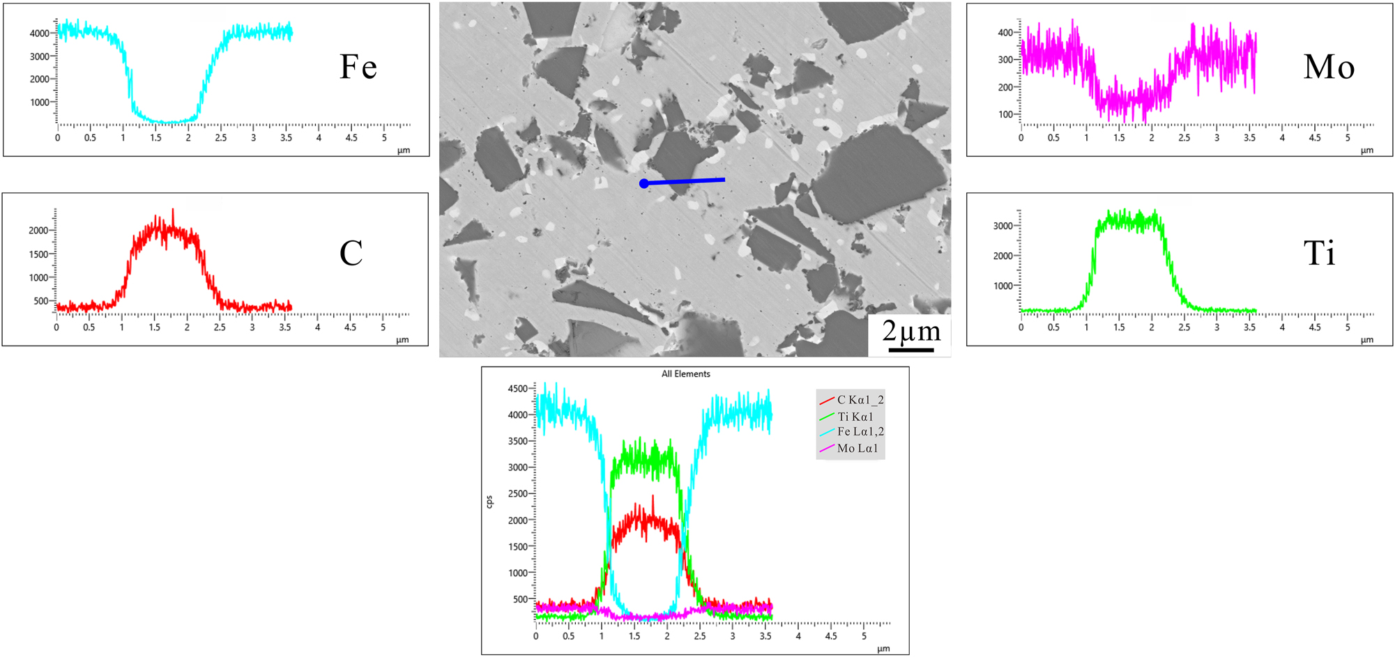
Elemental distribution determined by EDS linear scanning cross a hard particle of the heat-treated sample with 4.0 wt.% Mo. See also Figure 4c for larger scale.
Thermodynamic modeling can be performed to analyze the microstructure evolution process of the TiC–Fe cermets. However, there is still no complete thermodynamic database of the Fe–Mo–Ti–C system. Due to the limited solid solubility of Ti in Fe binder, M 6C and Mo2C phases, the thermodynamic parameters of the Fe–Mo–C system can also be used to analyze the microstructure of the alloys. Figure 7 illustrates the calculated vertical section of Fe–Mo–C system with different Mo contents. The maximum solid solubility of Mo in Fe binder was calculated to be 2.86 wt.% Mo, which is in agreement with the experimental result. For the cermet with 6.0 wt.% Mo (corresponding to 7.5 wt.% Mo in Fe–Mo–C system), the Fe–Mo–C alloy was located at the lower boundary of the two-phase region γ-Fe + M 6C at 1020 °C. As the temperature decreased, the Mo2C phase formed and the alloy reached the three-phase equilibrium γ-Fe + M 6C + Mo2C. It can be found that the thermodynamic calculation further verified the previous EDS analysis results.
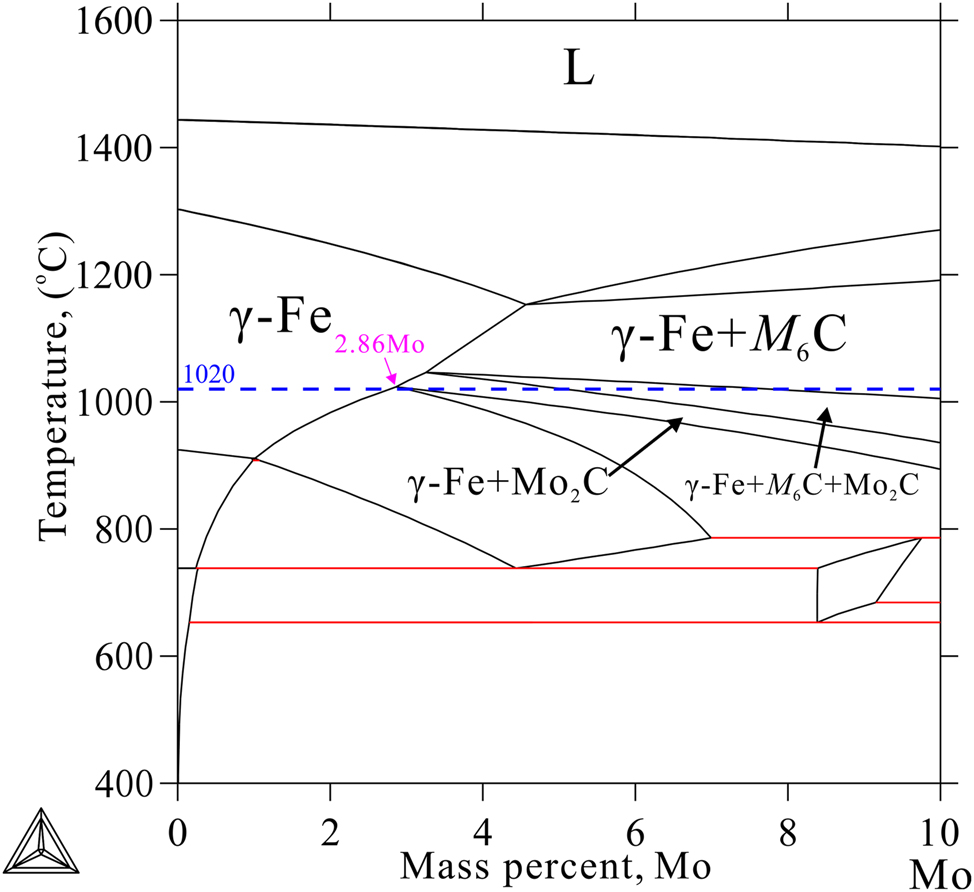
Calculated vertical section of Fe–Mo–C system with different Mo contents.
3.3 Density and mechanical properties
The relative density, Rockwell hardness and bending strength of the sintered and heat-treated samples with different Mo contents are summarized in Table 2. The relative density of all samples exceeded 96.6 %, which was consistent with the void free microstructure in Figures 3 and 4. It can be concluded that the mechanical properties of the alloy prepared in this work, including hardness and bending strength, were mainly controlled by the alloy compositions and microstructure, and little affected by the relative density. For the sintered cermets, the hardness was only 33.5 HRC at the Mo content of 0 wt.%. When 2.0 wt.% Mo addition was doped, the hardness significantly reached up to 55.0 HRC, which should be attributed to the solid solution strengthening mechanism of Mo in Fe binder. With the Mo content further increased, the trend of hardness enhancement gradually slowed down, and the highest hardness of 57.6 HRC was obtained for the sample with 6.0 wt.% Mo. Among all the sintered samples, the bending strength changed little with the increase in Mo content, ranging from 1115 to 1160 MPa. Compared with the mechanical properties of sintered samples, the hardness and bending strength of cermets can be improved clearly through the heat-treatment. The heat-treated sample with 4.0 wt.% Mo reached the highest hardness of 67.0 HRC, while the maximum bending strength of 1531 MPa was attained for the heat treatment sample with 2.0 wt.% Mo. It can be found that the bending strength of the heat-treated cermet with 6.0 wt.% Mo was significantly reduced to 1356 MPa due to the formation of a large amount of brittle M6C phase.
Properties of specimens.
| Sample | Sintered | Heat-treated | ||||
|---|---|---|---|---|---|---|
| no. | RD (%) | HRC | σ b (MPa) | RD (%) | HRC | σ b (MPa) |
| 1 | 97.4 | 33.5 ± 3.5 | 1115 ± 54 | 96.6 | 60.8 ± 2.5 | 1507 ± 122 |
| 2 | 98.5 | 55.0 ± 1.1 | 1145 ± 39 | 99.5 | 64.7 ± 1.1 | 1531 ± 102 |
| 3 | 99.4 | 57.0 ± 0.9 | 1149 ± 142 | 99.3 | 67.0 ± 0.9 | 1499 ± 4 |
| 4 | 99.1 | 57.6 ± 0.6 | 1160 ± 241 | 99.7 | 64.3 ± 0.5 | 1356 ± 166 |
-
Where RD, relative density; HRC, Rockwell hardness; and σ b, bending strength.
4 Conclusions
TiC–Fe cermets containing 0 to 6.0 wt.% Mo were fabricated by SPS method at 1020 °C. The influence of Mo contents on the microstructure and mechanical performance of TiC–Fe cermets was investigated. The following conclusions were drawn:
TiC-based hard particles and α-Fe constituted the major phases in the TiC–Fe–Mo cermets. The common core–rim structure was not formed during the SPS sintering process. Limited Mo was preferentially dissolved into the Fe binder, and excessive Mo precipitated in the alloy in the form of intermediate compounds.
Based on the EDS analyses and thermodynamic calculation, the intermediate compounds were determined as M 6C and Mo2C. Excessive Mo existed in the form of M 6C at high temperatures, and Mo2C precipitated from M 6C during the cooling process. M 6C was the dominant phase in the intermediate compounds.
The overall performance of the TiC–Fe cermets was improved significantly through the Mo addition and heat-treatment process. However, excess Mo led to the formation of brittle phase M 6C, which deteriorated the mechanical properties of the TiC–Fe cermets.
-
Research ethics: Not applicable.
-
Author contributions: The authors have accepted responsibility for the entire content of this manuscript and approved its submission.
-
Competing interests: The authors state no competing interests.
-
Research funding: This work was supported by the the National Natural Science Foundation of China (51901063) and Fundamental Research Funds for the Central Universities of China (JZ2023HGQB0163, PA2022GDGP0029 and PA2023GDGP0042).
-
Data availability: Not applicable.
References
1. Degnah, A.; Du, J.; Chandran, K. S. CALPHAD Approach and Processing of a Multicomponent Titanium Matrix Composite for High Strength and Fracture Toughness. Mater. Sci. Eng. A 2020, 781, 139210. https://doi.org/10.1016/j.msea.2020.139210.Suche in Google Scholar
2. Liu, Z.; Zhang, H.; Liu, X.; Zheng, Y.; Huang, X.; Zou, D. Effects of Diffusion Alloying on the Microstructure and Properties of TiC-Reinforced Fe-Based PM Materials. Int. J. Mater. Res. 2016, 107 (12), 1082–1090. https://doi.org/10.3139/146.111444.Suche in Google Scholar
3. Pachaury, Y.; Shin, Y. C. Assessment of Sub-surface Damage during Machining of Additively Manufactured Fe–TiC Metal Matrix Composites. J. Mater. Process. Technol. 2019, 266, 173–183. https://doi.org/10.1016/j.jmatprotec.2018.11.001.Suche in Google Scholar
4. Lin, F.; Du, Y.; Lv, J.; Zhang, C.; Liu, X.; Tan, Z. Effect of NbC on the Microstructure, Mechanical Properties, and Oxidation Resistance of Ti(C,N)-based Cermets. Int. J. Mater. Res. 2020, 111 (6), 479–490. https://doi.org/10.3139/146.111907.Suche in Google Scholar
5. Pan, Y. F.; Liu, A. J.; Huang, L.; Du, Y.; Jin, Y. Q.; Yang, X. Y.; Zhang, J. X. Effects of Metal Binder Content and Carbide Grain Size on the Microstructure and Properties of SPS Manufactured WC–Fe Composites. J. Alloys Compd. 2019, 784, 519–526. https://doi.org/10.1016/j.jallcom.2019.01.057.Suche in Google Scholar
6. Oh, N. R.; Lee, S. K.; Hwang, K. C.; Hong, H. U. Characterization of Microstructure and Tensile Fracture Behavior in a Novel Infiltrated TiC-Steel Composite. Scr. Mater. 2016, 112, 123–127. https://doi.org/10.1016/j.scriptamat.2015.09.028.Suche in Google Scholar
7. Li, G. P.; Yang, H.; Lyu, Y. H.; Zhou, H. J.; Luo, F. H. Effect of Fe–Mo–Cr Pre-alloyed Powder on the Microstructure and Mechanical Properties of TiC-High-Mn-Steel Cermet. Int. J. Refract. Met. Hard Mater. 2019, 84, 105031. https://doi.org/10.1016/j.ijrmhm.2019.105031.Suche in Google Scholar
8. Zhang, M.; Yang, Q. Q.; Xiong, W. H.; Zheng, L. Y.; Huang, B.; Chen, S.; Yao, Z. H. Effect of Mo and C Additions on Magnetic Properties of TiC–TiN–Ni Cermets. J. Alloys Compd. 2015, 650, 700–704. https://doi.org/10.1016/j.jallcom.2015.08.009.Suche in Google Scholar
9. Fu, Z. Z.; Kong, J.; Ram, G. S.; Koc, R. Sintering, Mechanical, and Oxidation Properties of TiC–Ni–Mo Cermets Obtained from Ultra-fine TiC Powders. J. Alloys Compd. 2018, 751, 316–323. https://doi.org/10.1016/j.jallcom.2018.04.124.Suche in Google Scholar
10. Liu, C.; Lin, N.; He, Y. H. Influence of Mo2C and TaC Additions on the Microstructure and Mechanical Properties of Ti(C,N)-based Cermets. Ceram. Int. 2016, 42, 3569–3574. https://doi.org/10.1016/j.ceramint.2015.10.168.Suche in Google Scholar
11. Liu, B. L.; Huang, S. G.; Van, H. J.; Vleugels, J. Influence of Mo Addition on the Microstructure and Mechanical Properties of TiC–NiTi Cermets. J. Alloys Compd. 2017, 712, 579–587. https://doi.org/10.1016/j.jallcom.2017.04.151.Suche in Google Scholar
12. Li, G. P.; Chen, W.; Wu, N.; Lyu, Y. H.; Guo, L. B.; Luo, F. H. Effect of Cr Content and its Alloying Method on Microstructure and Mechanical Properties of High-Manganese Steel-Bonded Carbide. Int. J. Refract. Met. Hard Mater. 2021, 101, 105698. https://doi.org/10.1016/j.ijrmhm.2021.105698.Suche in Google Scholar
13. Xu, Q. Z.; Zhao, J.; Ai, X.; Qin, W. Z.; Wang, D. W.; Huang, W. M. Effect of Mo2C/(Mo2C+WC) Weight Ratio on the Microstructure and Mechanical Properties of Ti(C,N)-based Cermet Tool Materials. J. Alloys Compd. 2015, 649, 885–890. https://doi.org/10.1016/j.jallcom.2015.07.144.Suche in Google Scholar
14. Huo, Y. Q.; Zhao, X. R.; Fang, Y. H.; Zhang, M. X. In Situ Synthesis Mechanism of Double Core/Rim Structure Ti(C,N)-based Cermets Prepared by Reactive Hot Pressing. J. Mater. Res. Technol. 2022, 19, 4439–4450. https://doi.org/10.1016/j.jmrt.2022.07.003.Suche in Google Scholar
15. Flem, M.; Allemand, A.; Urvoy, S.; Cédat, D.; Rey, C. Microstructure and Thermal Conductivity of Mo–TiC Cermets Processed by Hot Isostatic Pressing. J. Nucl. Mater. 2008, 380, 85–92. https://doi.org/10.1016/j.jnucmat.2008.01.033.Suche in Google Scholar
16. Jam, A.; Nikzad, L.; Razavi, M. TiC-based Cermet Prepared by High-Energy Ball-milling and Reactive Spark Plasma Sintering. Ceram. Int. 2017, 43 (2), 2448–2455. https://doi.org/10.1016/j.ceramint.2016.11.039.Suche in Google Scholar
17. Zhang, C.; Yin, H. Q.; Zhang, R. J.; Jiang, X.; Liu, G. Q.; Du, Y. Experimental and Thermodynamic Investigation of Gradient Zone Formation for Ti(C,N)-based Cermets Sintered in Nitrogen Atmosphere. Ceram. Int. 2017, 43 (15), 12089–12094. https://doi.org/10.1016/j.ceramint.2017.06.064.Suche in Google Scholar
18. Peng, Y. B.; Du, Y.; Zhou, P.; Zhang, W. B.; Chen, W. M.; Chen, L.; Wang, S. Q.; Wen, G. H.; Xie, W. CSUTDCC1-A Thermodynamic Database for Multicomponent Cemented Carbides. Int. J. Refract. Met. Hard Mater. 2014, 42, 57–70. https://doi.org/10.1016/j.ijrmhm.2013.10.005.Suche in Google Scholar
19. Chen, Q. Q.; Zhang, L.; Tang, S.; Liang, C. P.; Ma, Y. Z.; Liu, W. S. Examination of Dendritic Growth and Microsegregation during Solidification of Al–Li Binary Alloy Using the Phase-Field Simulation Coupling CALPHAD Data. Calphad 2021, 74, 102271. https://doi.org/10.1016/j.calphad.2021.102271.Suche in Google Scholar
20. Jacob, A.; Povoden-Karadeniz, E. Predictive Computations of Intermetallic σ Phase Evolution in Duplex Steel. (I) Thermodynamic Modeling of σ Phase in the Fe–Cr–Mn–Mo–Ni System. Calphad 2020, 71, 101998. https://doi.org/10.1016/j.calphad.2020.101998.Suche in Google Scholar
21. Sundman, B.; Jansson, B.; Andersson, J. O. The Thermo-Calc Databank System. Calphad 1985, 9, 153–190. https://doi.org/10.1016/0364-5916(85)90021-5.Suche in Google Scholar
© 2024 Walter de Gruyter GmbH, Berlin/Boston
Artikel in diesem Heft
- Frontmatter
- Original Papers
- Experimental investigation and thermodynamic analysis of TiC–Fe cermets with Mo additions
- Investigations on porous silicon nitride ceramics prepared by the gel-casting method
- Catalysis effect of rare earth element Ce on paste boriding treatment of AISI 410 steel
- Effect of nitrogen content on the static recrystallization and precipitation behaviors of vanadium–titanium microalloyed steels
- Effects of addition of Er and Zr on microstructure and mechanical properties of Al–Cu–Mn–Si–Mg alloy
- The quasi-binary phase diagrams of R 2Fe14B–Ce2Fe14B (R = Nd, Pr) systems
- Trivalent Gd incorporated Zn2SiO4 phosphor material for EPR and luminescence investigations
- Effects of translaminar edge crack and fiber angle on fracture toughness and crack propagation behaviors of laminated carbon fiber composites
- Blast protection of underwater tunnels with 3D auxetic materials
- News
- DGM – Deutsche Gesellschaft für Materialkunde