Dry reforming of methane over Ni/CeO2 catalysts prepared by three different methods
-
Nora Yahi
Nora Yahi is a PhD student at Mouloud Mammeri University, Tizi-ouzou (UMMTO), Algeria. Her research field is the preparation and characterization of nickel supported catalysis with different methods, applied in DRM. Currently she is teaching at the Faculty of Science and Technology (FST) of Blida.
 ,
Saliha Menad
,
Saliha Menad
Saliha Menad received her PhD degree in Applied Organic Chemistry, Option Catalysis from the Faculty of Science and Technology (FST) of Alger (Algeria) in 2007. Her research field is heterogeneous catalysis, synthesis, characterization and application of supported catalyst in DRM and Biginelli reaction.
Inmaculada Rodríguez-Ramos is a Research Professor at the Instituto de Catálisis y Petroleoquímica (ICP-CSIC) in Madrid where she heads the Group for Molecular Design of Heterogeneous Catalysts. Her research field is heterogeneous catalysis, applying C1 chemistry concepts to the production of hydrocarbons as well as hydrogen and with a particular specialization in carbon-based catalysts.

Abstract
Cerium-supported nickel catalysts with Ni loading close to 15%wt were synthesized using three different methods (microemulsion, sol-gel and autocombustion) with the aim to design efficient catalysts for the dry reforming of methane to produce syngas (H2+CO) from methane and carbon dioxide. The catalytic test was performed after calcining the as-prepared samples at 973 K, and subsequent in situ reduction was performed under hydrogen flow at 873 K. The resulting catalysts were characterized by X-ray diffraction (XRD), temperature-programmed reduction (TPR), transmission electron microscopy (TEM) and N2 adsorption-desorption isotherm measurements. The obtained results show that the Ni/CeO2 sample prepared by autocombustion is more active than a catalyst prepared by the sol-gel method, and the rate conversions of CH4 and CO2 are about 53%, 53% and 22%, 28%, respectively. The good activity of a catalyst prepared by the autocombustion can be due to the presence of the monoclinic phase of NiO revealed by the XRD and TPR characterizations. However, the catalyst prepared by the microemulsion method does not show any catalytic activity in this catalytic test.
1 Introduction
Today, there is great interest worldwide in developing the transformation of natural gas to syngas (H2+CO). As methane is the principal component in natural gas and carbon dioxide, one of the major greenhouse gas pollutants, their combination by the reforming reaction has received considerable attention [1–4]. Dry reforming of methane (DRM) CH4+CO2=CO+H2 permits obtaining syngas with the more suitable H2/CO ratio for Fischer-Tropsh synthesis [5]. In general, for this reaction, the catalysts used are transition metals (Ni, Co and Fe) [6] or noble metals (Pd, Rh, Ru, Pt and Ir) [7], which are deposited on various supports, such as alumina, silica and rare earths oxides [8]. Recently, novel metal-based catalysts have been found to be less sensitive to carbon deposition [1], but their high costs have limited their use as catalysts. Furthermore, supported Ni catalysts were largely applied for this type of reactions, due to their high activity and low cost [9]; however, these catalysts have a tendency to deactivate easily due to coke deposition, which causes plugging of the reactor and/or metal sintering [10, 11]. Morever, the activity as well as the stability of catalysts containing nickel depends strongly on the nature of the support [12, 13], the percentage in active phase [10–14], the nature of the metal additive [15] and the preparation method. Roh et al. [16] reported that the co-precipitation method is one of the promising methods to prepare highly active Ni-Ce-ZrO2 catalyst for catalytic reforming of methane, which can be hugely stabilized by adding ZrO2 to CeO2; also, they confirmed that CeO2 is one of the best supports for Ni-based catalysts. On the other hand, Xu et al. [17] used Ni-CeO2 catalyst, prepared by the precipitation method, for the reforming of methane with CO2 and O2. They found that Ce1-xNixO2 catalyst exhibited a good activity and strong resistance to coke deposition, while the Ni/Al2O3 and Ni/CeO2 catalysts deactivated rapidly due to nickel sintering and coke formation [18–21]. However, the good stability of the tested catalyst was related to the solid solution and the variety of cerium species in the Ce1-xNixO2 catalysts under high temperature and oxygen concentration on the gas phase. In another study, Pengpanich et al. [22] concluded that Ni/CeO2 and Ni-Ce0.75Zr0.25O2 catalysts prepared by the impregnation method were more active for partial oxidation of methane than those obtained by the sol-gel method and show higher activity than Ni/ZrO2 prepared by the impregnation method.
In fact, the Ni-supported CeO2 catalyst has been widely utilized in DRM; the Ni-Ce catalysts prepared by impregnation method showed low activity in this catalytic test with carbon dioxide, which can be due to the thermal sintering and carbon deposition that cause a loss of active sites and strong metal-support interaction that induce the coverage of active sites [23].
Over the past several years, cerium oxide and CeO2-containing materials have come under intense scrutiny as catalysts and as structural and electronic promoters of heterogeneous catalytic reactions [24, 25]. It has been reported that the addition of ceria improves the behavior of alumina-based catalysts used for automotive emission control [26]. CeO2 can store and reversibly release a large amount of oxygen, responding to the gas-phase concentration, which is called the oxygen storage capacity [27]. Its presence has other beneficial effects on the catalyst performance, such as improving the dispersion of the active phase or shifting the transition of the γ-Al2O3 used as support to the low-surface-area phase α-Al2O3 to higher temperatures [28]. CeO2 is applied as an effective promoter [29] and/or as support for Ni catalysts [30]. Several researches have reported the promotion effect of CeO2 in Ni/Al2O3 catalysts for CO2 reforming of methane [31, 32]. The authors found that CeO2, as a promoter, can enhance the activity, the stability and carbon resistance of these catalysts [33].
Although a great number of works about the catalytic performance of the Ni-ceria system for dry reforming reaction have been published in the last years, to our knowledge no studies have been performed comparing catalysts prepared by different procedures. In the present work, we have prepared Ni-CeO2 catalysts using three different synthesis methods (sol-gel, microemulsion and autocombustion). These preparation methods were selected in order to prepare catalysts with low particle size at low temperature. The as-obtained samples were tested as catalysts in the dry reforming reaction, and their activities were compared. The resulting Ni-CeO2 catalysts were characterized by X-ray diffraction (XRD), transmission electron microscopy (TEM), Brunauer–Emmett–Teller analyse (BET) and temperature-programmed reduction (TPR) in order to investigate the effect of the structural properties on their catalytic activity in the DRM process.
2 Materials and methods
2.1 Catalyst preparation
Three Ni-based catalysts were prepared using sol-gel, microemulsion and autocombustion methods; they were labeled Ni-Ce SG, Ni-Ce ME and Ni-Ce AT, respectively. All the reagents were of analytical grade and purity.
The preparation of supported Ni-Ce ME (15%wt of Ni) consists essentially in the preparation of an aqueous solution containing Ni(NO3)26H2O (99.8%, Merck) and cerium nitrate Ce(NO3)36H2O (99.5%, Merck) in 50 ml of distilled water. A water-oil microemulsion was prepared by mixing, while stirring, 50 ml (15.5%) of an aqueous solution containing the solution of Ni and Ce, with 187 ml (58%) of cyclohexane (99.8%, SDS), with 39 ml (12%) of butanol (99.5%, Riedel-de Haen) which acts as a co-surfactant, and 36.48 g (14.5%) of cetyltriammonium bromide (CTAB) (99%, Biochem) used as a surfactant. The same microemulsion containing the precipitating agent was prepared using ammonium hydroxide (30%, Panreac). These two microemulsions were stirred separately for 1 h at room temperature, then the second microemulsion was added to the first one dropwise with vigorous stirring (300 rpm) at room temperature for 20 h. The precipitating agent reacts rapidly with the metal precursors through the collision and coalescence between two aggregates containing the different reactants. The reaction (nucleation) will take place essentially at the same time in the whole microemulsion media which will favor the formation of a large number of nuclei inside the water cores of the inverse micelles. These nuclei will grow very quickly through material exchange between micelles (particle growth) to give the final particle size.
At this stage, inorganic particles stabilized by the surfactant molecules, and water-containing micelles, are suspended in the oil phase [34]. The resulting suspension was filtered. The remaining solid was washed with ethanol and acetone. The resulting solid was first dried at room temperature for 12 h then at 383 K for 24 h, and finally it was calcined in air for 8 h at 973 K using a ramp of 5 K/min.
The Ni-Ce sol-gel catalyst (15%wt of Ni) was prepared using the same starting nickel and cerium precursors. A mixture of adequate amounts of Ni(NO3)26H2O and Ce(NO3)36H2O was dissolved in 40 ml of distilled water at 298 K. Subsequently, 20 ml of saturated solution of stearic acid C18H36O2 (98%, Gpr Recctapur) was added to this mixture. The resulting solution was stirred at 353 K for 5 h. The gel prepared was dried at room temperature for 6 h then at 383 K for 24 h and finally calcined during 8 h in air at 973 K using a ramp of 5 K/min.
The Ni-Ce catalyst prepared by autocombustion (AT) (15%wt of Ni) was primarily prepared using the same procedure as the sol gel method; the only difference is in the addition of 10 g of CTAB and 30 ml of the saturated solution of stearic acid to the mixture in order to increase the dispersion of nickel over the support. Afterwards, the mixture was stirred, firstly, at 353 K for 5 h, and then when the temperature reached 553 K it gave rise to the autocombustion of the gel (exothermic reaction); the resulting solid was calcined for 8 h at 973 K.
2.2 Characterization methods
The elemental chemical analysis of catalysts was carried out by atomic absorption.
The BET surface areas of the catalysts were measured with N2 adsorption at N2 liquid temperature by using a micromeritics ASAP 2020 instrument. Prior to each measurement, the samples were degassed at 403 K in a vacuum for 1 h.
TPR was conducted with a BROOKS 5878 instrument in the Materials Research Laboratory. About 200 mg of the samples was loaded in a quartz reactor and heated from room temperature to 1023 K at a heating rate of 8 K/min in stream of (5%) H2 in Ar with total flow of 100 ml/min; the hydrogen consumption is determined as a function of the temperature.
Power XRD patterns were recorded on an Xpert Pro X-ray diffractometer with Cu/Kα radiation (λ=0.01544 nm) operating at 45 kV and 40 mA, ranging from 4 to 90°. The crystallite size was determined from the Scherrer-Warren equation [35].
The characterization of the as-obtained catalysts by TEM was performed with a JEOL 2100F field-emission gun electron microscope operated at 200 kV. The TEM specimens were prepared by dispersing a small sample amount in ethanol and placing one drop of the dispersion on a carbon-film-coated copper grid (3.0 mm, 200 mesh) allowing solvent evaporation.
2.3 Catalytic test
The catalytic activity of the prepared samples was performed in a fixed-bed tubular reactor (with an inner diameter of 9.5 mm) that was heated in an electric furnace equipped with a programmable temperature controller. Fresh 100 mg of catalysts, with a particle size between 150 and 250 μm, were diluted with silicon carbide (SiC) to obtain a 50 mm bed height and packed in the middle of the reactor. The temperature was monitored by a K-type thermocouple placed in the center of the catalyst bed. Before starting the reaction, the catalyst was reduced in situ at 873 K (maximum operation temperature) for 2 h with a mixture of 25 vol. % H2 in helium at a flow of 100 ml/min. After reduction, helium gas was used during 30 min to sweep the H2 from the reactor. The feed steam gas mixture consisted of CH4, CO2 and He to balance 1:1:8. The total flow rate was 100 ml/min. The reactant gases were measured-controlled by mass flow meters (Brook). The catalytic activity was measured at 873 K. Gas analyses of both reactants and products were carried out by on-line gas chromatography (Varian 3400) equipped with the thermal conductivity detector (TCD). Porapaq Q and Chromosorb 102 columns were used to separate the sample gas (CH4, H2, CO and CO2). Blank experiments were done to verify the absence of catalytic activity under the conditions used in this study, either with the reactor empty or filled with SiC. To discard the presence of diffusion problems, the experiments performed were replicated with other particle sizes, and both the flow rate and the catalyst amount were significantly changed while keeping the mass/flow rate ratio constant. The results obtained suggest the absence of both internal and external mass transfer effects. The carbon balance was close to 100% in all cases. The conversions (X), the yields (Y) and the H2/CO ratio are calculated as follows:
To investigate the stability of the Ni-Ce catalysts, the deactivation after 12 h of reaction was calculated as follows:
3 Results and discussion
3.1 Catalyst characterization
In all cases, the chemical composition of samples is in good agreement with the nominal value (Table 1). The BET surface areas of the catalysts are shown in Table 1. The Ni-Ce ME catalyst presents a higher specific surface area (49 m2/g) than that of Ni-Ce SG catalyst (45 m2/g). This result is in good agreement with those reported by Shan et al. [36], who found that the BET surface area of catalysts prepared by microemulsion is much higher than those prepared by the sol-gel method, with a large pore volume and pronounced mesoporosity. However, the Ni-Ce AT catalyst has a low specific surface area (34 m2/g) compared to the two others, which can be related to the high particles size of CeO2 support compared to that of catalysts prepared by microemulsion and sol-gel (Table 1).
Nominal composition, BET specific surface area of the prepared catalysts and their crystallite size obtained from the XRD patterns before and after TPR.
| Catalyst | Ni wt (%) | S (m2/g) | NiO (nm) | CeO2 (nm) | Ni (nm) (after TPR) |
|---|---|---|---|---|---|
| Ni-Ce ME | 14.7 | 49 | 34 | 11 | 11 |
| Ni-Ce SG | 14.9 | 45 | 11 | 11 | 11 |
| Ni-Ce AT | 15.2 | 34 | 11 | 34 | 11 |
Figure 1 shows the XRD patterns of fresh Ni-Ce catalysts. It can be seen that the as-obtained materials have a good crystallization. As shown from the patterns of the samples, the peaks at scattering angles of 28.54, 33.07, 47.47, 56.33, 59.07, 69.40 and 76.68° correspond to the CeO2 cubic system (00-034-0394, JCPDS) (Fm-3m, a=5.41 Å) for the three catalysts. Also, peaks attributed to NiO, cubic phase (01-078-0423, JCPDS) (Fm-3m, a=4.1 Å) are observed at 37.23, 43.26, 62.24 and 75.37° in case of Ni-Ce Me; however, NiO monoclinic (C2/m) (03-065-6920, JCPDS) are observed for Ni-Ce AT and Ni-Ce SG at 2θ 37.79, 43.6, 63.25 and 77.22°.
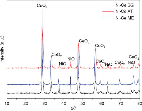
XRD patterns of studied catalysts prepared by autocombustion, sol-gel and microemulsion methods.
The comparison of particle sizes calculated by applying the Scherrer equation to the main NiO patterns show that Ni-Ce SG and Ni-Ce AT have a smaller particle size of nickel oxide phase (11 nm) than that of the catalyst obtained by microemulsion (34 nm) (Table 1), which also has a higher specific surface area.
The TPR profiles of H2 consumption for Ni-Ce catalysts are shown in Figure 2. The TPR profiles of the three samples showed a main peak located at 633, 622 and 628 K for Ni-Ce SG, Ni-Ce AT and Ni-Ce ME, respectively. This peak can be assigned to the reduction of bulk NiO phase to Ni0 [37, 38]. Morever, for the catalyst prepared by the sol-gel method, small peaks are observed at 517 K and 787 K. The first one can be attributed to the reduction of non-stoichiometric species Ni+3 [39, 40], the presence of free NiO particles [41] or hydrogen spillover effect [42], while the second one, much broader, can be assigned to the reduction of NiO interacting with support [43] or CeO2 reduction [44–46].
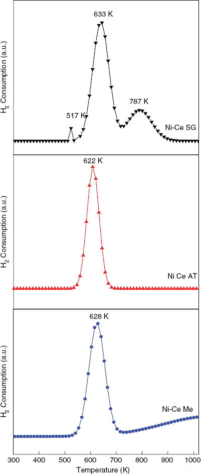
TPR profiles of Ni-Ce catalysts prepared by sol-gel, autocombustion and microemulsion.
On the other hand, the TPR profile of the Ni-Ce catalyst obtained by the microemulsion method shows a small hydrogen consumption around 900 K which can be due to the reduction of bulk CeO2 [11, 47].
All the samples resulting from the TPR analysis have been subjected to XRD analysis with the aim to show possible phase transition (Figure 3). The obtained patterns show well-defined peaks confirming the good crystallization of catalysts after TPR. Morever, there is complete disappearance of NiO following its reduction under the H2 flow, giving rise to the formation of Ni0 cubic system (Fm-3m, a=3.51 Å) (01-070-0989, JCPDS) (Figure 3) with the same crystallite size (11 nm) (Table 1).
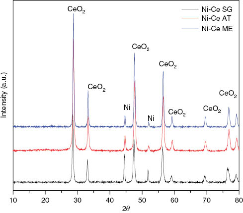
XRD patterns after TPR of the studied Ni-Ce catalysts.
3.2 Catalytic activity
The as-prepared catalysts were tested in DRM at 873 K after reduction at 823 K for 2 h with hydrogen gas. Figure 4 shows the CH4 and CO2 conversion and CO and H2 yield. The catalysts prepared by autocombustion and sol-gel method result in active catalytic reforming of methane; the rate conversions of CH4 and CO2 are about 53%, 53% and 22%, 28%, for samples obtained by autocombustion and sol-gel, respectively.

Conversion of CH4 and CO2, yield of CO and H2 (CH4:CO2:He)=(1:1:8), reduction temperature (Tr=873 K), calcinations temperature (Tc=973), and reaction time (tr=12 h) obtained from Ni-Ce catalysts prepared by autocombustion and sol-gel methods.
However, the catalyst Ni-Ce prepared by the microemulsion method does not show any catalytic activity in this catalytic test.
In fact, the good activity of the Ni-CeO2 catalyst prepared by sol-gel and autocombustion can be assigned to the small particle size of NiO (11 nm) and/or NiO monoclinic structure (Figure 1), compared to the catalyst prepared using microemulsion method which has, relatively, a large particle size (34 nm) and a NiO cubic structure (Table 1).
Ni-Ce AT catalyst is more active than Ni-Ce SG, the conversion rates of CH4 and CO2 in the range of 53%, and yields of H2 and CO of about 44% and 36%, respectively, with H2/CO ratio near to 0.82. During the reaction, the conversion rate of methane is similar to that of CO2; even the yield of CO is higher than that of H2, suggesting that besides methane dry reforming, reverse water-gas shift reaction (RWGS) CO2+H2→CO+H2O is also occurring, thermodynamically favored at low temperature.
In general, CO2 reforming of methane is typically accompanied by the simultaneous occurrence of a RWGS reaction [48–50]; the yield of CO is higher than that of H2 for both catalysts prepared by autocombustion and sol-gel (Table 2 and Figure 3) because a part of the hydrogen produced by DRM is consumed to produce CO from CO2, confirmed by the H2/CO ratio being always <1 (Table 2).
CH4, CO2 conversion, CO and H2 yield in catalytic reaction at 873° K, catalytic deactivation and CO/H2 ratio after 12 h of reaction.
| Catalysts | XCH4 % | XCO2 % | YCO % | YH2 % | H2/CO |
|---|---|---|---|---|---|
| Ni-Ce SG | 22 | 28 | 23 | 15 | 0.65 |
| Ni-Ce AT | 53 | 53 | 44 | 36 | 0.82 |
| Ni-Ce ME | – | – | – | – | – |
| Ni-CeO2 CP [16] | 92 | 93 | 94 | 91 | 0.98 |
| Ni-Ce ZrO2CP [16] | 97 | 97 | 98 | 95 | 0.97 |
The RWGS is very important in the case of Ni-Ce SG confirmed by H2/CO ratio (0.59) (Table 2), which may be due to the presence of nickel reduced at 787 K as given by TPR analysis (Figure 2). Wang et al. [51] conclude in their study of RWGS over co-precipitated Ni-CeO2 that the RWGS reaction is favored with catalysts presenting three kinds of nickel as detected by temperature-programmed reduction (TPR) analysis, and they assigned the main active sites for RWGS reaction to oxygen vacancies and highly dispersed nickel.
After 12 h of the reaction, a deactivation of 42% was observed with catalyst prepared by the autocombustion method. This latter can result from the sintering of metallic nickel particles or/and nanotube carbon deposition [10, 11].
For comparative purposes, we have compared the results obtained by the present work with those presented in the literature [17] (Table 2), Roh et al. obtained a high catalytic activity with Ni-CeO2 and Ni-Ce-ZrO2 catalysts, with Ni loading close to 15%wt and prepared by the co-precipitation method. The high stability was obtained when they promoted the cerium with ZrO2 since no deactivation was detected after 100 h of the reaction.
The tested catalysts were characterized by TEM after 12 h of the reaction in order to show their structures and the possible relationship with their deactivation cause. In fact, the deactivation of Ni-Ce SG and Ni-Ce AT can result from the sintering of metallic nickel particles confirmed by TEM micrographs observation (Figure 5); we have also observed an accumulation of carbon nanotubes on both catalysts (Ni-Ce AT and SG) but in a bigger extension on the Ni-Ce SG sample.

TEM image of Ni-Ce catalysts prepared by sol-gel (A, B, C), autocombustion (D, E, F) and microemulsion (G, H, I) before (A, D, G) and after 12 h of reaction.
In their study, Trovarelli et al. [24] showed that all carbon species formed on Ni-CeO2 prepared by wetness impregnation method were present in oxidized carbon forms, and they found that the oxidized carbon species are less active towards gasification; this carbon can cover the nickel sites acting as the deactivating factor, thus resulting in fast deactivation.
4 Conclusion
In the present work, we have prepared three Ni-CeO2 catalysts using sol-gel, microemulsion and autocombustion methods. The resulting catalysts were characterized by XRD, BET and TPR analysis and tested in the catalytic reforming of methane. The XRD analysis shows a good crystallization of all catalysts, with peaks assigned to the CeO2 cubic system and monoclinic NiO in the case of Ni-Ce AT and Ni-Ce SG; however, cubic NiO was observed for catalyst prepared by the microemulsion method.
Although Ni-Ce ME catalyst presents a high surface area (49 m2/g), Ni-CeO2 prepared by autocombustion is found to be more active in the methane reforming test; the catalytic tests show that the conversions of CH4 and CO2 are near to 53%, and H2 and CO yields are 44% and 36%, respectively, with the H2/CO ratio near 1 (0.82). It is probably due to the monoclinic structure of NiO (observed by XRD analysis) uniformly dispersed over the support (confirmed by TPR characterization). After 12 h of reaction, the deactivation of about 42% was observed, which can result in the sintering of metallic nickel particles or/and nanotube carbon deposition confirmed by TEM micrographs.
About the authors

Nora Yahi is a PhD student at Mouloud Mammeri University, Tizi-ouzou (UMMTO), Algeria. Her research field is the preparation and characterization of nickel supported catalysis with different methods, applied in DRM. Currently she is teaching at the Faculty of Science and Technology (FST) of Blida.

Saliha Menad received her PhD degree in Applied Organic Chemistry, Option Catalysis from the Faculty of Science and Technology (FST) of Alger (Algeria) in 2007. Her research field is heterogeneous catalysis, synthesis, characterization and application of supported catalyst in DRM and Biginelli reaction.

Inmaculada Rodríguez-Ramos is a Research Professor at the Instituto de Catálisis y Petroleoquímica (ICP-CSIC) in Madrid where she heads the Group for Molecular Design of Heterogeneous Catalysts. Her research field is heterogeneous catalysis, applying C1 chemistry concepts to the production of hydrocarbons as well as hydrogen and with a particular specialization in carbon-based catalysts.
References
[1] Bradford MCJ, Vannice MA. Catal. Rev. Sci. Eng. 1999, 41, 1–42.Search in Google Scholar
[2] Rostrup-Nielsen JR. Stud. Surf. Sci. Catal. 1994, 81, 25–41.10.1016/S0167-2991(08)63847-1Search in Google Scholar
[3] Stagg-Williams SM, Noronha FB, Fendley G, Resasco DE. J. Catal. 2000, 194, 240–249.Search in Google Scholar
[4] Liu ZW, Roh HS, Jun KW. J. Ind. Eng. Chem. 2003, 9, 261–266.Search in Google Scholar
[5] Courty P, Chaumette P. Energy Progress. 1987, 7, 23–30.Search in Google Scholar
[6] Choudhary VR, Rane VH, Rajput AM. Catal. Lett. 1993, 22, 289–297.Search in Google Scholar
[7] Tsang SC, Claridge HB, Green MLH. Catal. Today 1995, 23, 3–15.10.1016/0920-5861(94)00080-LSearch in Google Scholar
[8] Nakagawa K, Ikenaga N, Suzuki T, Kobayashi T, Haruta M. Appl. Catal. 1998, 169, 281–290.Search in Google Scholar
[9] Ferreira-Aparicio P, Guerrero-Ruiz A, Rodriguez-Ramos I. Appl. Catal. A: General 1998, 170, 177–187.10.1016/S0926-860X(98)00048-9Search in Google Scholar
[10] Lercher JA, Bitter JH, Hally W, Niessen W, Seshan K. Stud. Surf. Sci. Catal. 1996, 101, 463–472.Search in Google Scholar
[11] Wang S, Lu GQ. Energy Fuels 1998, 12, 248–463.10.1021/ef970092mSearch in Google Scholar
[12] Roh HS, Jun KW, Baek SC, Park SE. Catal. Lett. 2002, 81, 147–151.Search in Google Scholar
[13] Yokota S, Okumura K, Niwa M. Catal. Lett. 2002, 84, 131–134.Search in Google Scholar
[14] Wang S, Lu GQ. Ind. Eng. Chem. Res. 1999, 38, 2615–2625.Search in Google Scholar
[15] Hou Z, Yokota O, Tanaka T, Yashima T. Catal. Lett. 2003, 87, 37–42.Search in Google Scholar
[16] Roh HS, Potdar HS, Jun KW. Catal. Today 2004, 93–95, 39–44.10.1016/j.cattod.2004.05.012Search in Google Scholar
[17] Xu S, Yan X, Wang X. Fuel 2006, 85, 2243–2247.10.1016/j.fuel.2006.03.022Search in Google Scholar
[18] Du X, Zhang D, Shi L, Gao R, Zhang J. Phys. Chem. 2012, 116, 10009–10016.Search in Google Scholar
[19] Gonzalez-Dela Cruz VM, Holgado JP, Pereníguez R, Caballero A. J. Catal. 2008, 257, 307–314.Search in Google Scholar
[20] Odedairo T, Chen J, Zhu Z. Catal. Commun. 2013, 31, 25–31.Search in Google Scholar
[21] Xu W, Liu Z, Johnston-Peck AC, Senanayake SD, Zhou G, Stacchiola D, Stach EA, Rodriguez JA. ACS Catal. 2013, 3, 975–984.Search in Google Scholar
[22] Pengpanich S, Meeyoo V, Rirksomboon T. Catal. Today 2004, 93–95, 95–105.10.1016/j.cattod.2004.06.079Search in Google Scholar
[23] Wang SB, Lu GQ. Appl. Catal. B 1998, 19, 261–267.10.2530/jslsm1980.19.4_261Search in Google Scholar
[24] Trovarelli A. Catal. Rev.-Sci. Eng. 1996, 38, 439–520.Search in Google Scholar
[25] Martínez-Arias A, Hungria AB, Fernández-García M, Conesa JC, Munuera G. J. Phys. Chem. 2004, B 108, 17983–17991.Search in Google Scholar
[26] Gunter PLJ, Niemantsverdriet JW, Riebeiro FH, Somorjai GA. Catal. Rev.-Sci. Eng. 1997, 39, 77–168.Search in Google Scholar
[27] Yao HC, Yao YFY. J. Catal. 1984, 86, 254–256.Search in Google Scholar
[28] Morterra C, Bolis V, Magnacca G. J. Chem. Soc., Faraday Trans. 1996, 92, 1991–1999.Search in Google Scholar
[29] Qin Z, Ren J, Miao M, Li Z, Lin J, Xie K. Appl. Catal. B: Environmental 2015, 164, 18–30.10.1016/j.apcatb.2014.08.047Search in Google Scholar
[30] Yu M, Zhu Y, Lu Y, Tong C, Zhu K, Zhou X. Appl Catal. B: Environmental 2015, 165, 43–56.10.1016/j.apcatb.2014.09.066Search in Google Scholar
[31] Cheng ZX, Wu QL, Li JL, Zhu QM. Catal. Today 1996, 30, 55–147.10.1016/0920-5861(95)00005-4Search in Google Scholar
[32] Wang CY, Li SY, Yang XR, Ren J, Chen YG. Energy Convers. Mgmt. 1996, 37, 1357–1361.Search in Google Scholar
[33] Wang S, PhD thesis, The University of Queensland, 1998.Search in Google Scholar
[34] Boutonnet M, Lögdberg S, Elm Svensson E. Curr. Opin. Colloid Interface Sci. 2008, 13, 270–286.Search in Google Scholar
[35] Klug HP, Alexander LE. X-ray Diffraction Procedures for Polycrystalline and Amorphous Materials, John Wiley and Sons, Inc.: New York, 1974.Search in Google Scholar
[36] Shan X, Zhao R, Wang X. Fuel Process. Technol. 2004, 86, 123–133.Search in Google Scholar
[37] Junichiro K, Subramani V, Song C, Engelhard M, Chin Y. J. Catalysis 2006, 238, 430–440.10.1016/j.jcat.2006.01.001Search in Google Scholar
[38] Diskin AM, Cunninghan RH, Ormerod RM. Catal. Today 1998, 46, 147–154.10.1016/S0920-5861(98)00336-8Search in Google Scholar
[39] Arena F, Licciardello A, Parmaliana A. Catal. Lett. 1990, 6, 139–150.Search in Google Scholar
[40] Frusteri F, Freni S, Chiodo V, Donato S, Bonura G, Cavallaro S. Int. J. Hydrogen Energy 2006, 31, 2193–2199.10.1016/j.ijhydene.2006.02.024Search in Google Scholar
[41] Roh HS, Jun KW, Dong W, Chang J, Park SE, Joe Y. J. Mol. Catal. A 2002, 181, 137–142.Search in Google Scholar
[42] Pengpanich S, Meeyoo V, Rirksomboon T, bunyakiat K. Appl. Catal. A 2002, 234, 221–233.10.1016/S0926-860X(02)00230-2Search in Google Scholar
[43] Shi Q, Liu C, Chen W. J. Rare Earth 2009, 27, 948–954.10.1016/S1002-0721(08)60368-3Search in Google Scholar
[44] Léiu BS, Au CT. Catal. Lett. 2003, 85, 165–170.Search in Google Scholar
[45] Perrichon V, Laachir A, Bergeret G, Fréty R, Tournayan L, Touret O. J. Chem. Soc. Faraday Trans. 1994, 90, 773–781.Search in Google Scholar
[46] Fajardie F, Tempere JF, Manoli JF, Djega-Mariadassou G. J. Chem. Soc. Faraday Trans. 1998, 94, 3727–3780.Search in Google Scholar
[47] Barrault J, Alouche A, PaulBoncour V, Hilaire L, PercheronGuegan A. Appl. Catal. 1989, 46, 269–279.Search in Google Scholar
[48] Soria MA, Mateos-Pedrero C, Guerrero-Ruiz A, Rodríguez-Ramos I. Int. J. Hydrogen Energy 2011, 36, 15212–15220.10.1016/j.ijhydene.2011.08.117Search in Google Scholar
[49] Nikoo MK, Amin NAS. Fuel Process. Technol. 2011, 92, 678–691.Search in Google Scholar
[50] Bachiller-Baeza B, Mateos-Pedreroa C, Soria MA, Guerrero-Ruiz A, Rodemerck U, Rodríguez-Ramos I. Appl. Catal. B: Environmental 2013, 129, 450–459.10.1016/j.apcatb.2012.09.052Search in Google Scholar
[51] Wang L, Zhang S, Liu Y. J. Rare Earth 2008, 26, 66–70.10.1016/S1002-0721(08)60039-3Search in Google Scholar
©2015 by De Gruyter
This article is distributed under the terms of the Creative Commons Attribution Non-Commercial License, which permits unrestricted non-commercial use, distribution, and reproduction in any medium, provided the original work is properly cited.
Articles in the same Issue
- Frontmatter
- In this issue
- Original articles
- Rapid colorimetric detection of Hg2+ ion by green silver nanoparticles synthesized using Dahlia pinnata leaf extract
- Chemically modified Retama raetam biomass as a new adsorbent for Pb(II) ions from aqueous solution: non-linear regression, kinetics and thermodynamics
- Dry reforming of methane over Ni/CeO2 catalysts prepared by three different methods
- Microstructure and wear behavior of Al-Al2O3in situ composites fabricated by the reaction of V2O5 particles in pure aluminum
- Company profile
- Austrian small enterprise Microinnova GmbH receives “Process Intensification Award for Industrial Innovation 2015” from the European Federation for Chemical Engineering (EFCE)
- Conference announcement
- Conferences 2016–2017
- Book reviews
- Biohydrogen
- Green chemistry for dyes removal from waste water
- Green chemistry strategies for drug discovery