Microstructure and wear behavior of Al-Al2O3in situ composites fabricated by the reaction of V2O5 particles in pure aluminum
-
Amneesh Singla
Amneesh Singla is a graduate in Mechanical Engineering from Maharishi Dayanand University, Rohtak, India and a postgraduate from Deakin University, Australia. He has taken research projects in the fields of Tribology and Metal Matrix Composites. Mr. Singla has more than 6 years of teaching experience as well as 5 years of industrial experience and has published various research papers in various refereed national and international journals. He is presently working as an Assistant Professor in the Mechanical Engineering Department, University of Petroleum and Energy Studies, Dehradun, India.
 ,
Rajnish Garg
,
Rajnish Garg
Rajnish Garg obtained his BE, ME and PhD degrees, respectively, in the field of Mechanical Engineering, Materials Engineering and Fiber Reinforced Metal Matrix Composites from Indian Institute of Technology (IIT) Roorkee, India. Dr. Garg has more than 20 years of teaching/research/industry experience. He has guided many PhD students and published many research papers in various refereed national and international journals. Presently, he is a professor in the Mechanical Engineering Department, University of Petroleum and Energy Studies, Dehradun, India.
Mukesh Saxena obtained his PhD degree in the field of Mechanical Engineering from RECK IIT Delhi. Dr. Saxena has more than 30 years of experience in teaching and research. He has published many research papers in various refereed national and international journals. Presently, he is working as Pro Vice Chancellor at University of Technology and Management, Shilong, India.

Abstract
In this study, fabrication of Al based in situ composites and their formation mechanism is investigated through the stir casting approach. In situ composites were prepared with the addition of various amounts of V2O5 particles in pure aluminum. Due to the reaction of vanadium pentoxide with the molten aluminum, Al2O3 (alumina) is formed. X-ray diffraction (XRD), scanning electron microscopy (SEM) and microscopy were used for the examination of the produced in situ composites. Increment in hardness was observed in cast in situ composites as compared to the pure aluminum. Friction and wear behaviors of cast in situ composites were studied by using a pin on disc tribo tester. The investigation showed that the wear loss and coefficient of friction increases with the load. The result indicates that wear rate increases with higher percentage of addition. The different phases formed are shown by the XRD study and the presence of Al3V and alumina in the composite enhanced the properties.
1 Introduction
Worldwide, aluminum alloys has a wide range of applications in many areas due to the advantages of its associated mechanical and tribological properties [1–3]. Among nonferrous materials, aluminum shows better strength to weight ratio, resistance to corrosion, ductility and very low cost [4]. However, the applications of pure aluminum are restricted due to their poor wear resistance and softness. This problem is ended by the reinforcement of hard particles in aluminum and its alloys. A number of hard ceramic particles like SiC [5], TiB2 [6], MoO3 [7], ZnO [8], ZrB2 [9], TiO2 [10] etc. were incorporated in aluminum alloys to enhance their wear properties. Great improvement has been reported in wear and mechanical properties by the addition of nonmetallic phases like borides, nitrides, oxides and carbides into aluminum alloys [11, 12]. Reinforcement of particles in the aluminum matrix can be achieved by two methods; ex situ and in situ. The reinforcement particles can be externally added or can be generated within the matrix. Aluminum based ex situ composites show low bonding strength between the matrix and reinforcement, whereas in situ composites have better adhesion [13, 14]. The in situ method is very economical and provides better mechanical and wear properties as compared to ex situ, due to uniform distribution of reinforcement particles into matrix, and formation of thermodynamically stable phases [15].
A new technique, particulate reinforced metal matrix composite (PRMMC), has been suggested for the formation of Al2O3 particulates by the in situ reaction. The SO3 decomposed from Al2(SO4)3 improves the bonding between aluminum based matrix and Al2O3 and provides good strength [16]. Another work for the formation of alumina particles by the in situ reaction has been reported. In this case, alumina particles were formed by the reduction of CuO and silicon oxide. The tensile properties were significantly improved due to the presence of alumina particles. The strain hardening effect was observed due to the presence of particles in the composite sample [17]. A chemical reaction between CeO2 and molten aluminum was carried out by the direct molten reaction (DMR) process for the formation of Al2O3 by the in situ reaction. The investigation reveals that the strength of cast composites was increased because of Al2O3 particles. High density dislocation around the alumina particles was found to be responsible for the composite strengthening [18]. A much less amount of energy is required to produce aluminum as compared to the steel. Aluminum composites are strong and infinitely recyclable. This has very favorable impact on the environment. None of its production processes involve significant risks for health or the environment. The in situ reaction takes place within the melt and only heat escaped out. In fact, the aluminum industry has been very concerned over the years in reducing pollution and the effects on the environment.
In the present work, an in situ approach has been used for the preparation of Al-Al2O3 composites by the reaction between pure aluminum and V2O5 particles. The intention of this study is to investigate the microstructure and wear properties of in situ aluminum composites obtained by the dispersion of V2O5 particles in different amounts. Addition of a small amount of magnesium improves the wettability of alumina particles and enhances the reaction process.
2 Materials and methods
2.1 Fabrication and characterization of in situ composites
Commercially available pure Al and extra pure AR grade V2O5 particles were used in this experiment. The average size of V2O5 particles was 159.9 nm, as measured by a Malvern particle size analyzer. About 1100 g of pure aluminum containing 99.68% Al, 0.14% Fe and 0.18% Si was used. The elemental composition was determined by the optical emission spectrometer (SPECTROMAXx, Ametek, Germany). The temperature range for the Al/V2O5 composite was determined by differential scanning calorimetry analysis. Figure 1 represents the differential scanning calorimetry analysis for the sample selected; exothermic and endothermic peaks were found. The first endothermic peak starts at 650°C, which corresponds to the melting of aluminum and further it proceeds towards the exothermic reaction between aluminum and vanadium pentoxide subsequent to the formation of Al2O3. The exothermic peak was observed at around 850°C as per reaction (2) shown below, which results in the formation of Al3V:
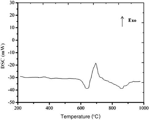
Differential scanning calorimetry (DSC) analysis of Al and V2O5.
So, according to the reaction, the Al3V intermetallic in situ compound is formed in molten aluminum. The aluminum is melted at 850°C in a bottom pouring stir casting furnace from Swam Equipment (Hasthinapuram, Chennai, Tamil Nadu, India) as shown in Figure 2. The stirrer blade used in the experiment is made of stainless steel and before use, the stirrer is coated with a fine paste of graphite and dried so that no dissolution of steel in molten aluminum takes place.
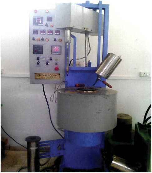
Bottom pouring stir casting apparatus.
Experiments have been conducted with different percentages of vanadium pentoxide. The different amounts of V2O5 are weighed according to the particles selected for addition. Before the addition, particles are preheated at 250°C in order to remove moisture content or any other gases which are present in the reinforcement. Preheating of particles also avoids significant decrease in temperature [19]. The addition rate is controlled by the knob equipped in the setup. For melt temperature measurement, the thermocouple is placed in the melt chamber. The process parameters used in the experiment are mentioned in Table 1.
Process parameters used.
| Parameters | Variables used |
|---|---|
| Melt temperature | 850°C |
| Particle preheating temperature | 250°C |
| Die temperature | 250°C |
| Stirrer rpm | 800 |
| Time of processing | 15 min |
| Amount of V2O5 added (wt.%) | 3, 5, 7 and 9 |
When the melt temperature reaches 850°C, a small amount (5 g) of Mg is added in the melt in the presence of argon gas and V2O5 is added at a very slow rate in to the melt. The addition of magnesium promotes wettability of in situ generated particles and retains them inside the melt. The position of the stirrer is kept constant to disperse the V2O5 particles into the melt. The stirrer speed is kept at 800 rpm to form the vortex. After 15 min of stirring, the melt is poured in to a preheated cylindrical graphite mold of length 165 mm and inner diameter 45 mm. Degassing of the melt is carried out at this stage for vacuum casting. The cast in situ ingot is now allowed to cool in still air. Same parameters have been used for the entire in situ ingot with various wt.% of V2O5.
X-ray diffraction (XRD) using a D8 Advance from Bruker (Germany), using Cu Kα radiation, optical microscope, optical emission spectrometer was used for characterization. Before metallographic examination, Keller’s reagent was used for polishing and etching purposes of the specimens. The optical microscope from Nikon (Japan) was used for the microstructure evaluation.
2.2 Dry sliding wear test
Tribological behaviors of various composites were investigated using a pin on disc tribometer from Ducom (Bangalore, India) as per standard test methods of ASTM G99-95. For the data acquisition system, a personal computer is connected with the tribometer. Linear variable differential transformer (LVDT) is used for determination of the wear in micrometers and sensors are mounted to sense the changes in the frictional forces. Weight of the pin was determined before the test was conducted and after the tested result. Weight loss of the pin was determined as a function of different load applied and sliding distances. Weighing was performed with an analytic balance Shimadzu AX 200 machine with a sensitivity of 0.01 mg.
Flat cylindrical pins of 10 mm diameter and 30 mm height were used for the test. The counter face disc has a maximum diameter of 165 mm and is made up of EN-31 steel hardened to 60 HRC. The thickness of the disc=08 mm and the limit of disc track diameter=145 mm. The chemical composition of EN31 steel is C 1, Si 0.35, Mn 0.5, S 0.05, P 0.05, Cr 1.3 and Fe balanced. Before conducting each experiment, ethyl alcohol was used to ensure that the surfaces were cleaned properly. The entire tests were conducted at ambient temperature with track diameter=40 mm (for each experiment). The loads applied were 10 N, 20 N and 30 N with sliding distance 1000 m. The sliding velocity for all of the experiments was 0.83 m/s. The samples were cleaned and polished with 400, 600, 800 and 1000 grit paper. Emery paper A350 was used for polishing the disc after each experiment. After completion of each test, the pin and disc specimen was cleaned ultrasonically with ethyl alcohol and stored in a vacuum oven furnace to avoid corrosion of the material. For the examination of the worn surfaces, a trinocular stereo zoom microscope was used. The mean average value was used after completing each experiment three times to maintain accuracy in the results.
3 Results and discussion
3.1 Thermodynamics characteristics of the in situ reaction
According to thermodynamic aspects, pure vanadium is formed by the reduction of V2O5 as shown in reaction (3). The vanadium formed reacts with excess aluminum and forms Al3V as shown in reaction (4):
The negative value of
3.2 XRD analysis
The phases identified by the XRD technique are presented in Figure 3. Al3V and Al2O3 were identified in Al-V2O5 composites. In case of 5% V2O5 addition, strong peak was observed in comparison to 3% and 7% addition due to complete reaction between Al and V2O5. Reduction of aluminum can be easily identified with decrement of the peaks with the increment of particle addition. Two phases appeared apart from aluminum in XRD, i.e. Al3V and Al2O3; according to the Al-V phase equilibrium diagram Al21V2, Al45V7 and Al23V7 are metastable over a temperature of 736°C.
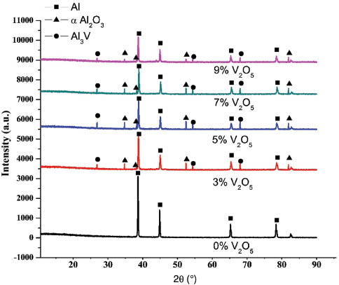
X-ray diffraction (XRD) pattern for cast in situ composite synthesized at 850°C.
Al2O3 formations due to the in situ reaction were verified by a simple chemical test. About (3.0 g) of V2O5in situ composite samples were dissolved in hydrochloric acid (2 m) without attacking the unreacted V2O5 and Al2O3 particles [20]. For settling the fine particles, sodium sulfate (0.1 m) was used. The insoluble oxide particles were filtered out using Whatman ashless filter paper and the filtrate was heated up to 900°C for 1 h and allowed to cool down. After filtration, the residue is collected for the mass determination of alumina. The maximum recovery of the particles extracted was 78.21%. An XRD study was conducted using the Bruker (Germany) D8 Advance, with two theta range from 15 deg to 90 deg using Cu Kα radiation. The XRD of the cast 5% V2O5 composite is shown in Figure 4. XRD results clearly show the formation of alumina particles due to the in situ reaction between pure aluminum and V2O5 particles. The scanning electron microscopy (SEM) image of extracted particles is shown in Figure 5.
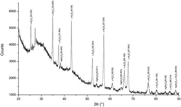
X-ray diffraction (XRD) pattern of filtered residue obtained from composite Al (5 g Mg)-5% V2O5, synthesized at 85°C.

Scanning electron microscopy (SEM) image of extracted particles.
3.3 Microstructural evaluation
Micrograph of the Al with various percentage additions of V2O5 is shown in Figure 6. Figure 6A shows the microstructure of pure aluminum and Figure 6B and C indicate the grain refinement of aluminum alloy due to 3% and 5% addition of particles, respectively. Figure 6D shows the microstructure for 5% addition at higher magnification. The grain size of pure Al and the composite made by 5% addition was measured with the help of metallurgy plus software. The average grain size measured for Al was 1 μm. In the case of 5% composite, the average grain size was reduced from 1 μm. The reduction in the grain size was found to be due to the effect of vanadium. The grain size refinement indicates the homogeneous distribution of vanadium pentoxide particles in aluminum and formation of alumina due to complete in situ reaction. However, the particles are segregated at the grain boundaries due to pushing of particles at 3% composition, whereas at higher composition, i.e. at 5%, a complete reaction occurs which is shown in the microstructure. Al2O3 particulates are settled along the grain boundaries in a rod shape and a homogenous composite formed. In the case of 7%, a large number of oxide particles agglomerate at the grain boundaries and into the crystal structure.

(A) micrograph of pure aluminum; (B) shows the micrograph Al-3% V2O5; (C) Al-5% V2O5 at low magnification; (D) Al-5% V2O5 at high magnification; (E) Al-7% V2O5 at low magnification; (F) Al-7% V2O5 at high magnification.
3.4 Microhardness and tensile strength
Table 2 shows the mechanical properties of pure Al and various cast Al-V2O5 composites. Microhardness has been measured for the more than 20 region points at 200 gf load with 5 s dwell time.
Mechanical properties and porosity content for different reinforcementsa.
| Sampleb | Material | Microhardness (HV) | UTS (MPa) | Elongation (%) | Porosity content (vol.%) |
|---|---|---|---|---|---|
| A | Pure Al | 25.4 (1.01) | 39.1 (6.7) | 3.25 (0.4) | 2.730 |
| AV3 | Al-3% V2O5 | 58.2 (1.45) | 57.3 (4.8) | 5.73 (0.7) | 2.420 |
| AV5 | Al-5% V2O5 | 62.3 (1.82) | 64.8 (2.6) | 7.12 (1.3) | 2.100 |
| AV7 | Al-7% V2O5 | 58.7 (2.03) | 60.7 ((3.5) | 6.44(0.8) | 3.040 |
| AV9 | Al-9% V2O5 | 47.8 (1.32) | 49.4 (2.4) | 4.21 (0.5) | 3.810 |
aStandard deviations are shown within parentheses.
bA stands for aluminum, V stands for V2O5 and the last digit represents the wt.% of oxide added.
A major increment in hardness is observed in the cases of AV3 and AV5. The increment in hardness is due to solid solution hardening, where V reduced from V2O5 and dissolved in molten metal. The solid solution hardening is the effect attained by adding the alloying elements into the matrix. The solid solution hardening is a result of an interaction between mobile dislocations and the solute atoms. The presence of solute atoms increases the initial yield stress and reduces the dynamic recovery rate of dislocations. According to Hall-petch, grain boundaries perform as a barrier for dislocation slip and refine grains provide more area to resist the movement of dislocation. The micrograph shows the grain refinement. The grain size refinement creates a high volumetric density of grain boundaries which impede the dislocation movement and propagation to adjacent grains, thereby consequently strengthening the material [21, 22]. Also, good distribution of V2O5 particles acts as an obstacle for the dislocation movement and forms the dislocation loops. According to the Orowan mechanism movement of dislocation is quite difficult in the case of a loop rather than a line [23, 24]. Dispersion of Al2O3 and intermetallic compound in the matrix also contributed to the hardness increment.
Figure 7 shows that sample AV5 indicates the maximum microhardness compared with other samples. Further addition of V2O5 results in decrease of hardness. The reason for hardness decrement is dendritic growth and release of latent heat. Agglomerations of a large number of particles in the crystal and at grain boundaries were also responsible for hardness decrement. AV7 has low density as compared to the pure Al and indicates the presence of porosity which is also a reason for low hardness.

Variation of microhardness with amount of V2O5 added.
The tensile strength of AV5 is higher than that of the other composites as well as pure aluminum. Strengthening is possible due to the presence of Al2O3 and V particles in the matrix.
Figure 8 shows the tensile fracture surfaces of cast composites with 5% and 7% addition of V2O5. The fracture surface shows some dimple ductile fracture in some areas as shown in Figure 8A, but also certain a area represents the shear fracture which results in the elongation of about 7%. Figure 8B shows the presence of dimples and the porosity (3.04). The presence of porosity is found to be responsible for the decrease in hardness as mentioned in Table 2.
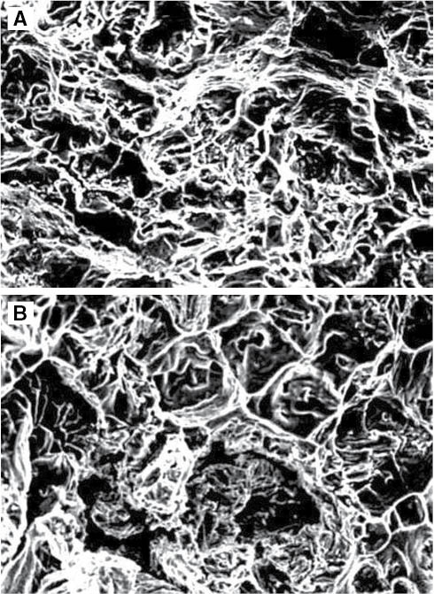
(A) scanning electron microscopy (SEM) showing the tensile fracture surface of composite with 5% addition; (B) SEM image of tensile fracture Al-7% V2O5.
Ductility plays an important role and affects the mechanical properties. Table 2 shows the ductility value with various percentages of V2O5 addition. Ductility increases until the 5% reinforcement, therefore tensile strength also increases. Higher reinforcement of more than 5% increases the porosity content as shown in the SEM image. In the case of 7%, less tensile strength is reported due to porosity.
3.5 Coefficient of friction analysis
Figure 9 shows the variation of friction coefficient with respect to sliding distance at different loads, i.e. 10 N, 20 N and 30 N which was applied at a sliding velocity of 0.83 m/s. Generally, friction coefficient increases with increase of load. It is observed from the figure that the maximum coefficient of friction was shown by the pure aluminum. There was a significant decrease in the coefficient of friction with the addition of oxide particles of V2O5. A decrease of about 4.18%, 5.17% and 12.78% was observed in the coefficient of friction for composites containing 3 wt.%, 5 wt.% and 7 wt.%, respectively, in comparison to pure aluminum. The significant decrease in the coefficient of friction can be attributed to the formation of a lubricating layer between the metals in contact. This tribo layer formation was due to smaller particle size of V2O5. Lower value of coefficient of friction was due to proper dispersion of particles into the aluminum matrix [25].

(A) Coefficient of friction as a function of sliding distance at 10 N load; (B) coefficient of friction as a function of sliding distance at 20 N load; (C) coefficient of friction as a function of sliding distance at 30 N load.
A comparative plot was measured in the steady state region for coefficient of friction with respect to load, as shown in Figure 10. As stated earlier, coefficient of friction increases with increase of load and composites with 7 wt.% V2O5 had minimum coefficient of friction. The coefficient of friction was decreased around 10% in the case of 3% and 5 wt.% addition, whereas in case of 7 wt.% addition 20% decrement was observed at 10 N load. At 20 N loads, a significant decrease was observed in the coefficient of friction due to the addition of 3 wt.%, 5 wt.% and 7 wt.%, which was about 5.5%, 16.6% and 19.4%, respectively.

Coefficient of friction as a function of various loads.
3.6 Volume loss
Figure 11 shows the variation of pin volume loss as the function of load for 1000 m sliding distance (steady state regime). A decrease in volume loss was observed in the cast in situ composite as compared to pure aluminum. The comparison of volume loss at 10 N, 20 N and 30 N with sliding distance 1000 m is shown in Figure 9. At the highest load (30 N), a reduction in volume loss was observed in as cast in situ composites as compared to pure aluminum. The volume loss observed was about 20%, 33.3% and 46% for Al 3%, Al 5% and Al 7% cast samples, respectively. The porosity content in cast composites was a little higher than that in pure aluminum. Therefore, the reduction in volume loss in in situ composites over the pure aluminum could be attributed to the effect of reinforcing particles in the aluminum matrix.
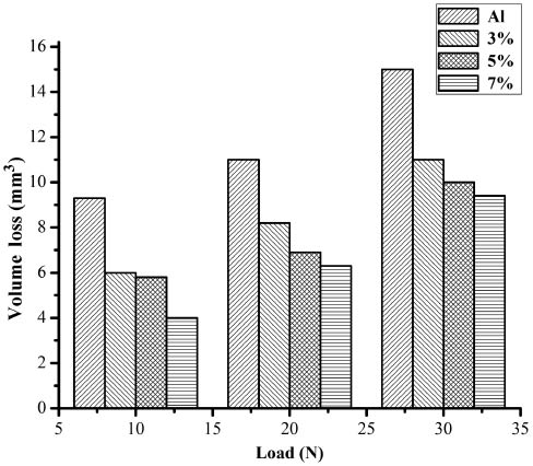
Relationship between volume loss at different loads for cast in situ composites.
3.7 Wear
Figure 12 shows the wear behavior of pure aluminum and cast composites with addition of V2O5. It is well known that the dry sliding wear of in situ composites decreases significantly by increasing the amount of reinforcing particles [26]. However, some researchers reported that the cast composites contain porosity due to increase in particle content, which tends to decline their behavior against wear. The porosity of the cast composites was found to be due to the poor wetting of the reinforced particles in aluminum melt [27].
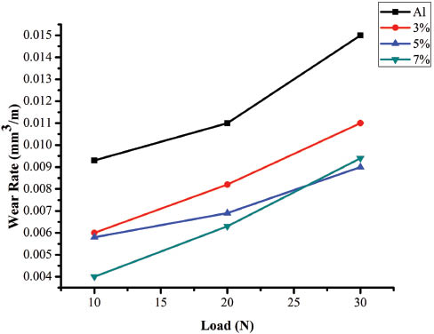
Wear rate of pure Al and cast in situ composite as a function of load.
From Figure 12, it was observed that with higher percentage of V2O5 particles wear decreases. With the addition of oxide particles, hardness increases and decreases the real area of contact. During the dry sliding test, the oxide debris was generated. This hard debris locked between the surfaces and promotes wear. However, at the same time, particles get compacted between the surfaces and form a protective transfer layer. This layer is responsible for the decrease in wear rate [28]. However, for 7% addition specific wear rate tends to increase. This increase was due to the presence of porosity in cast in situ composites. The porosity also affects the hardness and tensile properties as reported in Table 2. The real area of contact increases with higher porosity and eventually increases the wear rate. So, the effect of porosity is not only softening the material, but it also promotes the delamination and subsurface cracks.
The worn surface of material mainly depends on speed and applied load. At low load due to the micromachining effect, a proportion of counter face material is removed and subject to oxidation. This oxidized material (Fe2O3) acts as a tribo layer between the two surfaces. Wear studies reported that the wear rate temporarily reduces due to the tribo layer formation. This tribo layer acts as a solid lubricant between the mating surfaces. At high load, delamination was found as shown in the figure due to the removal of the tribo layer. At high load, high temperature is generated at near surfaces and reduces the shear strength in subsurface layers which promotes the excessive material transfer. The best result of wear rate has been found in the case of 5% addition as compared to the 7% addition. Micrographs of worn surfaces at different loads with 5% and 7% addition are shown in Figure 13. At low load, small grooves were observed on worn surfaces in the sliding direction due to an abrasion mechanism. However, in the case of higher load, delamination occurs as the real area of contact increases and eventually the fracture stresses of reinforced particles increase. The presence of alumina and intermetallic compound in the cast in situ composite provides hardness, but if the porosity increases, interaction between the matrix and reinforcement decreases.
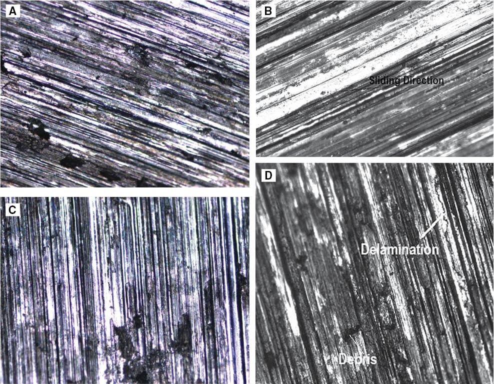
Micrographs of (A) worn surface for 5% at 20 N load; (B) worn surface for 5% at 30 N load; (C) worn surface for 7% at 20 N load; and (D) worn surface for 7% at 30 N load.
4 Conclusion
An in situ aluminum metal matrix composite was developed using pure aluminum ingot and V2O5 particles. The microstructure and effects on microhardness were measured and analyzed. The dry sliding wear behavior of aluminum and cast in situ composites containing different wt.% of oxide particles was investigated. The effect of oxide particles addition and porosity on wear was evaluated. The conclusions were summarized as follows:
An in situ composite was formed due to the reduction of V2O5 particles by molten aluminum as revealed by the XRD study. Aluminum melt liberates the vanadium ions first, which further reacts with molten aluminum and forms an Al3V intermetallic compound. The extent of reduction increases with increasing the percentage of oxide particles up to 5%.
Increment in microhardness is observed to be approximately 2.5 times more than that of pure aluminum in the case of composites formed by the 5% addition of V2O5. The reaction found in this case is nearly complete and formation of Al2O3 and Al3V was found to responsible for improvements in hardness and microstructure.
Vanadium acts as a grain refiner and in the microstructure, grain refinement is observed. From the experiments it was observed that the addition of a small amount of V2O5 particles gives appreciable results.
The coefficient of friction value was found to be low in the case of in situ composites as compared to pure aluminum.
Wear rate of in situ cast composites seems to be lower in comparison to aluminum. In the case of 7% additions of oxide particles, more wear was observed.
About the authors

Amneesh Singla is a graduate in Mechanical Engineering from Maharishi Dayanand University, Rohtak, India and a postgraduate from Deakin University, Australia. He has taken research projects in the fields of Tribology and Metal Matrix Composites. Mr. Singla has more than 6 years of teaching experience as well as 5 years of industrial experience and has published various research papers in various refereed national and international journals. He is presently working as an Assistant Professor in the Mechanical Engineering Department, University of Petroleum and Energy Studies, Dehradun, India.

Rajnish Garg obtained his BE, ME and PhD degrees, respectively, in the field of Mechanical Engineering, Materials Engineering and Fiber Reinforced Metal Matrix Composites from Indian Institute of Technology (IIT) Roorkee, India. Dr. Garg has more than 20 years of teaching/research/industry experience. He has guided many PhD students and published many research papers in various refereed national and international journals. Presently, he is a professor in the Mechanical Engineering Department, University of Petroleum and Energy Studies, Dehradun, India.

Mukesh Saxena obtained his PhD degree in the field of Mechanical Engineering from RECK IIT Delhi. Dr. Saxena has more than 30 years of experience in teaching and research. He has published many research papers in various refereed national and international journals. Presently, he is working as Pro Vice Chancellor at University of Technology and Management, Shilong, India.
References
[1] Hamid AA, Ghosh PK, Jain SC, Ray S. Wear 2006, 265, 14–26.10.1016/j.wear.2007.08.018Search in Google Scholar
[2] Gao Y, Zhu DG, Cheng L, Wang Q. Adv. Mater. Res. 2011, 38–42, 284–286.Search in Google Scholar
[3] Zhang J, Yu HS, Chen HM, Min GH. China Foundry 2010, 7, 19–23.Search in Google Scholar
[4] Xu J, Liu W. Wear 2006, 260, 486–492.10.1016/j.wear.2005.03.032Search in Google Scholar
[5] Rao RN, Das S. Mater. Des. 2010, 31, 1200–1207.Search in Google Scholar
[6] Kumar S, Chakraborty M, Sarma VS, Murty BS. Wear 2008, 265, 134–142.10.1016/j.wear.2007.09.007Search in Google Scholar
[7] Li YF, Qin CD, Ng DHL. J. Mater. Res. 1999, 14, 2997–3000.Search in Google Scholar
[8] Yu P, Deng C-J, Ma N-G, Ng DHL. Mater. Lett 2004, 58, 679–682.10.1016/j.matlet.2003.06.001Search in Google Scholar
[9] Dinaharan I, Murugan N. Trans. Nonferrous Met. Soc. China 2012, 22, 810–818.10.1016/S1003-6326(11)61249-1Search in Google Scholar
[10] Maity PC, Chakraborty PN, Panigrahi SC. Mater. Lett. 1994, 20, 93–97.Search in Google Scholar
[11] Al-Jarrah JA. PhD Thesis, University of Roorkee, India, 1998, pp. 206–221.Search in Google Scholar
[12] Banerji S, Surappa MK, Rohatgi PK. Metall. Mater. Trans. 1993, 14B, 273–279.Search in Google Scholar
[13] Kumaresh K, Babu SP, Natarajan S, Narayanasamy R, Dinesh G. Mater. Sci. Eng. A 2008, 498, 495–500.10.1016/j.msea.2008.09.003Search in Google Scholar
[14] Mandal A, Chakraborty M, Murty BS. Wear 2007, 262, 160–166.10.1016/j.wear.2006.04.003Search in Google Scholar
[15] Kumar S, Chakraborty M, Sarma VS, Murthy BS. Wear 2008, 265, 134–142.10.1016/j.wear.2007.09.007Search in Google Scholar
[16] Liuzhang O, Chengping L, Xiandong S, Meiqin Z, Min Z. Mater. Lett. 2003, 57, 1712–1715.Search in Google Scholar
[17] Hoseini M, Meratian M. Mater. Lett. 2005, 59, 3414–3418.Search in Google Scholar
[18] Hongming W, Li G, Zhao Y, Chen G. Mater. Sci. Eng. A 2010, 527, 2881–2885.10.1016/j.msea.2010.01.022Search in Google Scholar
[19] Ghosh PK, Ray S. J. Mater. Sci. 1987, 22, 4077–4086.Search in Google Scholar
[20] Haynes WM. Handbook of Chemistry and Physics, 61st ed., CRC Press: Boca Raton, FL, 1980–81, pp. B-74–118.Search in Google Scholar
[21] Lavernia EJ, Han BQ, Schoenung JM. J. Mater. Sci. Eng. A 2008, 493, 207.10.1016/j.msea.2007.06.099Search in Google Scholar
[22] Witkin DB, Lavernia EJ. Prog. Mater. Sci. 2006, 51, 1.Search in Google Scholar
[23] Subramanian R, McKamey CG, Schneibel JH, Buck LR, Menchhofer PA. Mater. Sci. Eng. 1998, 254, 119–123.Search in Google Scholar
[24] Zhang Z, Chen D. Scr. Mater. 2006, 54, 1321–1326.Search in Google Scholar
[25] Yi H, Ma N, Zhang Y, Li X, Haowei W. Scr. Mater. 2006, 54, 1093–1097.Search in Google Scholar
[26] Rohatgi PK, Liu Y, Ray S. D. Henry Scott (Ed.), Handbook Vol. 18, ASME, 1997, pp. 802–811.Search in Google Scholar
[27] Ray S. J. Mater. Sci. 1993, 28, 5397–5413.Search in Google Scholar
[28] Ray S, Tesfay AW, Nath SK. Wear 2009, 266, 1082–1090.10.1016/j.wear.2009.01.033Search in Google Scholar
©2015 by De Gruyter
This article is distributed under the terms of the Creative Commons Attribution Non-Commercial License, which permits unrestricted non-commercial use, distribution, and reproduction in any medium, provided the original work is properly cited.
Articles in the same Issue
- Frontmatter
- In this issue
- Original articles
- Rapid colorimetric detection of Hg2+ ion by green silver nanoparticles synthesized using Dahlia pinnata leaf extract
- Chemically modified Retama raetam biomass as a new adsorbent for Pb(II) ions from aqueous solution: non-linear regression, kinetics and thermodynamics
- Dry reforming of methane over Ni/CeO2 catalysts prepared by three different methods
- Microstructure and wear behavior of Al-Al2O3in situ composites fabricated by the reaction of V2O5 particles in pure aluminum
- Company profile
- Austrian small enterprise Microinnova GmbH receives “Process Intensification Award for Industrial Innovation 2015” from the European Federation for Chemical Engineering (EFCE)
- Conference announcement
- Conferences 2016–2017
- Book reviews
- Biohydrogen
- Green chemistry for dyes removal from waste water
- Green chemistry strategies for drug discovery