Preparation of Na2HPO4⋅12H2O-based composite PCM and its application in air insulated box
-
Maosheng Zheng
 ,
Yuebei Li
,
Yuebei Li

Abstract
In order to provide continuous supply for succeeding application, abundant electricity energy and solar energy can be stored by means of thermal storage technology. In the present paper, the heat energy storage/exothermic tests are conducted to evaluate the performance of thermal energy storage and release of electricity energy in the self – designed heat storage box equipped with the composite phase change material (PCM), the delivery of heat to surrounding environment is through an air blower directly. The composite PCM consisting of Na2HPO4⋅12H2O and Na3PO4⋅12H2O at the ratio of 7:3 is used to carry out the tests, which is with stable solidification property. Following results are obtained from this research: (1) The solidification temperature of the composite PCM is 33.4 °C with reduced supercooling degree of 2.6 °C; (2) The is phase change exothermic enthalpy value of the composite PCM is 178.02 J/g; (3) The self – designed “peak load shifting” heat storage equipment for electricity energy is with the energy exchange efficiency of 89.59%. The achievements of this research show the applicability of the thermal storage technology by means of the composite PCM.
Introduction
At present, the excessive use of fossil energy has caused deterioration of environment gradually and shortage of fossil energy, which in turn become a limiting factor for economic growth. Therefore, the structure of energy resource is facing adjustment worldwide, sustainability and coordination with the environment and resources will be the unavoidable direction in future. The structure change of energy resource has become an important and hot research topic, which involves a number of very complex factors (Hou, Xu, and Cheng 2008). It is necessary to adjust the energy structure so as to demand of the continuous development of economy and environment for human life.
Exploration and application of renewable energy, such as wind energy, solar energy, geothermal energy, et al., has been developed rapidly. Ha et al. proposed a simple and effective trailing edge flap system consisting of a motor-driven worm gear drive and flexible torsion bar (Ha 2020). A preliminary level design study was performed to show the applicability of the new trailing edge flap system for wind turbine rotor blade or helicopter blade.
As alternatively important measurement for sustainable energy development, heat storage technology has received extensive attention. The abundant electricity energy and solar energy can be stored by means of thermal storage technology for its continuous supply in form of heat energy. As an example, the abundant electric energy can be restored in the form of heat in the valley period of electricity consumption, and the restored heat energy can be released during the peak period of electricity consumption, which can be delivered to the user to play the role of “shifting load peak”; In addition, abundant solar energy can also be restored in form of heat during daytime period, and the released when needed. Therefore, heat storage technology has broad development prospects for the implementation of energy structure adjustment, energy saving and emission reduction.
Kıvanç et al. made a tank filled with water and marble as a heat store to replace the general wall (Kıvanç and Wall 2019), the developed Trombe wall system could provide 30% of the energy required for heating and cooling of the building. Wahba et al. employed green roofs/walls to adjust the urban heat island effect by simulation (Wahba et al. 2019), which could adjust the outdoor air temperature by 10 °C and improve the outdoor thermal comfort by 2 predicted average values (PMV). Qerimi et al. made solar water heaters to replace the traditional water heaters for 38,289 residential households in Pristine of Kosovo (Qerimi et al. 2020), the initial cost of the solar water heater is 60113730 €, the system saves 7274910 € annually and reduces CO2 emission by 22973400 kg.
Kibaara et al. developed tool by modeling to assess the techno-economic and the environmental impacts in monetary form (Kibaarae et al. 2020), which is able to determine the viability of a plant in a given region.
Phase change material (PCM) is another main thermal energy storage medium, which can be used in heat storage technology. According to its chemical composition, PCM can be classified into organic PCM, inorganic PCM, and composite PCM. Inorganic hydrated salt is a typical PCM.
Research status
Research status of phase change materials (PCMs)
Ahmet et al. studied the thermal properties of composite PCMs of fatty acids and their eutectic mixture attempting to use the heat storage materials in the fields of building (Ahmet 2003; Ahmet and Kamil 2001; Gulseren and Ahmet 2003), low – temperature heating and solar energy systems (Ahmet and Kamil 2006; Kadir et al. 2004).
German researchers have found that paraffin wax could be encapsulated as microcapsules with size of 1–20 μm by poly-methylmethacrylate (PMMA) (Gschwander and Henning 2005; Schossig, Gschwander, and Haussmann 2005). The wall thickness of the microcapsules is less than 20 nm, which is easy to be dispersed in water without agglomeration. In the molten state, there is no interaction between the paraffin microcapsules and the liquid carrier, and the microcapsule is expected to be used in low temperature field.
Walsh et al. used hydrated inorganic for night cold storage (Walsh, Murray, and O’Sullivan 2013), and numerical calculations showed that the operating time can be reduced by 67% during peak electricity consumption.
Xu et al. found that the composite PCM made from paraffin/diatomite has good compatibility with cement (Xu and Li 2014), and the composite material has good structural uniformity with excellent energy storage and thermal insulation performances.
Li et al. analyzed the PCM gypsum board of lauric acid – decanoic acid in the field of building by means of the enthalpy method model (Li, Cheng, and He 2013). Their results show that the latent heat utilization rate of this gypsum board is 38.7%, which could save energy by 27.6% as compared to the ordinary walls with the same structure.
The application status of PCMs in “peak load shifting” heat storage device of electricity energy
The “peak load shifting” of electricity can be implemented to alleviate the grid load by heat storage equipment. The design and application research of “peak load shifting” equipment with PCMs in domestic is in primary stage, and detailed work needs to be done.
Brousseau and Lacroix applied the multi-layer phase change material system in an electric heating system to meet the demand of balancing the electricity load (Brousseau and Lacroix 1996). The performance of the heat storage unit is simulated with corresponding mathematical model. The results showed that the melting within the PCM is inhomogeneous, especially the material at the bottom is not completely molten even though the temperature at the top of the heat storage unit is very high owing to the improper arrangement of the heater and the heat storage unit.
Xu and Li once analyzed the feasibility of applying energy storage electric heating technology in the Guanzhong area of Shaanxi province of China (Xu and Li 2019). Their research shows that heat storage of electric heating needs a comprehensive consideration of mature technology, safety, and initial installation. It is feasible to promote thermal storage electric heaters. Mazzeo et al. comparatively conducted an experiment employing a PCM with an analytical model so as to carry out the evaluation of the thermophysical properties of the PCM sample, the analytical model constitutes a valid algorithm for the evaluating the latent and sensible contribution and the trend of the position of the bi-phase interface in time (Mazzeo and Oliveti 2017; Mazzeo and Oliveti 2018; Mazzeo et al. 2017). Halford et al. addressed a potential peak air conditioning load shifting strategies using encapsulated phase change materials. The PCM was designed to be installed within the ceiling or wall insulation to perform the delay of the peak air conditioning demand time (Halford and Boehm 2007).
In general, the cost of inorganic PCMs is superior to that of organic PCMs, such as paraffin wax, et al.
In recent years, Zheng et al. improved the thermal storage properties and heating – cooling circling behaviors of Na2HPO4⋅12H2O based PCM by adding Na2SO4⋅10H2O (Jin et al. 2019; Zheng, Liu, and Jin 2019a; Zheng et al. 2019b), and anti-corrosive property with addition of Na2SiO3⋅9H2O by compositing material technology. However, the phase transformation temperature of the Na2HPO4⋅12H2O based PCM is around 30 °C (Jin et al. 2019; Zheng, Liu, and Jin 2019a; Zheng et al. 2019b), which is still lower for some usage.
The main content of this paper
This paper aims to conduct preparation Na2HPO4⋅12H2O-based composite PCM with higher phase transformation temperature by other additive, and characterize performance analysis of by step-cooling test, DTA test, etc., and then the heat storage and release performance of the material in a self manufactured insolated air box, in which the delivery of heat with surrounding environment is through an air blower directly. The flowchart of the research in this paper is shown in Figure 1.

Flowchart of the research in this paper.
Basic property of Na2HPO4·12H2O based composite material
Experimental materials and setups
The experimental materials are shown in Table 1, and the setups used in the experiment are shown in Table 2. The test tubes used in the experiment are all plastic test tubes with a diameter of 20 mm and a volume of 50 mL.
Experimental materials.
| Name of material | Grade | Manufacturer |
|---|---|---|
| Na2HPO4·12H2O | Industrial grade, 98% purity, 25 kg/bag | Shifang Xuhongda chemical plant |
| Na3PO4⋅12H2O | Industrial grade, 98% purity | Shifang Xuhongda chemical plant |
Experimental setup.
| Instrument | Model | Producer | Parameters of performance |
|---|---|---|---|
| Electronic balance | JJ124BC | Changshu Shuangjie Exp. Equip. Factory | Accuracy 0.1 mg, maximum range 200 g |
| Water bath with heater & stirrer | DF-101S | Gongyi Zhi China Instrument Co., Ltd. | Heating temperature 0–400° |
| Thermometer | TM-902C | Shanghai Jiamin Instrument Co., Ltd. | Temperature range −50–750 °C |
| DTA-TG instrument | HCT-1 | Beijing Hengjiu Sci. Instru. Factory | |
| Thermocouple sensor | k | Changzhou Tengde Electronics Co., Ltd. | Range: 50–1200 °C |
| Single layer glass reactor | DF-10L | Zhengzhou Scitech Biotech. Co., Ltd. | Speed: 1000 g/cm Capacity: 10L |
Thermal performance of phase change materials
Disodium hydrogen phosphate dodecahydrate (Na2HPO4·12H2O) is a typical crystalline hydrated salt used for energy storage material. In recent years, it has attracted more attention (Hiran et al. 2015; Huang et al. 2013; Lan et al. 2009), but it has a supercooling of 13 °C, which limits its practical application. One aim of this study is to reduce the supercooling of Na2HPO4·12H2O by additive chemicals. The additive Na3PO4⋅12H2O is with industrial grade with purity of 98%. From the experimental results of the mass ratios of Na2HPO4·12H2O to Na3PO4⋅12H2O at 5:5, 8:2, 7:3 and 9:1, it found that the ratio of 7:3 obtained lowest degree of supercooling and promising phase transition temperature. So, the composite of Na2HPO4·12H2O with additive Na3PO4⋅12H2O at 7:3 is used here for further investigation.
Step cooling curve of the composite
The composite of Na2HPO4·12H2O with additive Na3PO4⋅12H2O at 7:3 is used here for detailed analysis.
40 g of the composite material is placed into the test tube, which is then sealed with waterproof tape. The test tube is placed in a 60 °C constant temperature water bath for heating until the composite salt molten completely and kept there for half an hour. Then, remove the test tube out of the water bath and place it in a cooling water bath at temperature of 20 °C, as shown in Figure 2. The step – cooling curve (solid process) of the composite salt was by obtained in the cold water bath, and the temperature was recorded every 2 s, which is shown in Figure 3. It can be seen from Figure 3 that the solidification temperature of the composite material is 33.4 °C, the heat release plateau is about 37.5–39 °C with the duration of heat release of 40 min.
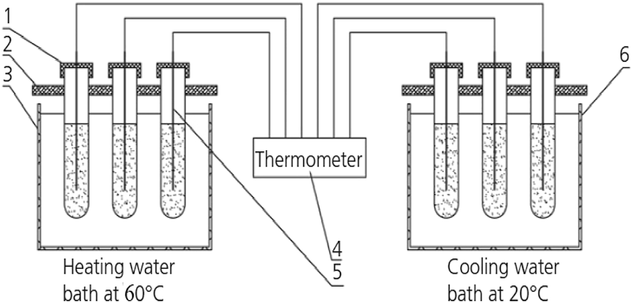
Diagram of melting-solidification test for composite PCM. (1) - tube cover and sealing tape; (2) - test tube clip; (3) - water bath with heater & magnetic stirrer; (4) - thermometer; (5) - thermometer sensor; (6) - cooling water bath.
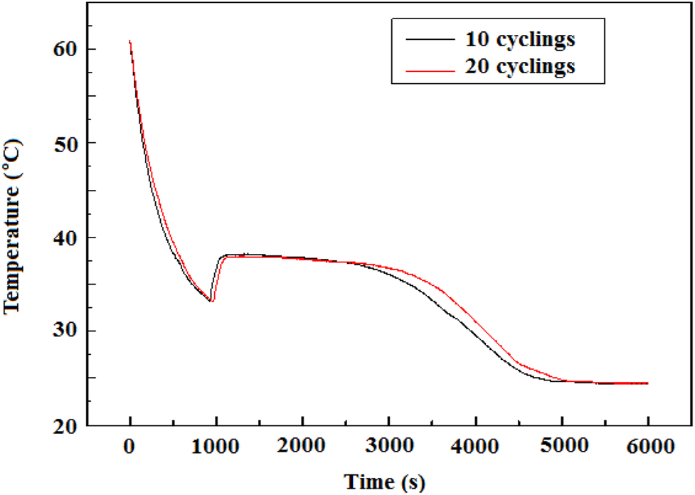
Step cooling curve of the composite Na2HPO4·12H2O- Na3PO4⋅12H2O.
DTA –TG test
The DTA test for the composite Na2HPO4·12H2O- additive Na3PO4⋅12H2O is carried out at the DAT-TG HCT-1 instrument. The temperature of DTA test ranges from 20 to 180 °C at the heating rate of 1 °C/min. The experimental results are shown in Figure 4.
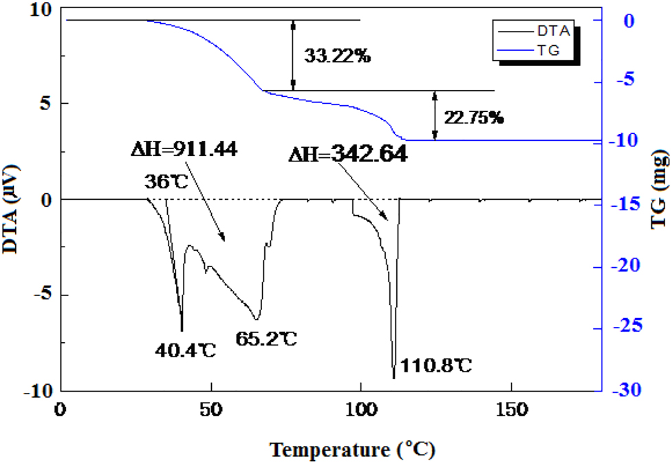
DTA curve of composite Na2HPO4·12H2O- additive Na3PO4⋅12H2O.
It can be seen from Figure 4 that there are three absorption peaks during the heating process. The peak temperatures are 40.4, 65.2, and 110.8 °C, and the corresponding enthalpy change is 911.44, 342.64 J/g, Na3PO4⋅12H2O, respectively. There are two weight loss steps for the composite phase change material, i.e., a weight loss step rate of 33.22% ranging 30–65 °C and a weight loss step rate of 22.75% ranging 65–110 °C. Extrapolating the first endothermic peak to the baseline of temperature, it obtains the initial phase transition temperature of the composite phase change material being 36.0 °C, see Figure 4.
As compared with the solidification temperature of the composite phase change material given in Figure 3, i.e., 33.4 °C, the supercooling degree of the composite is 2.6 °C, which indicates that this composite phase change material has lower supercooling degree and promising latent heat performance in the low temperature range. The supercooling degree of this composite phase change material is much smaller than those mentioned in literatures (Hiran et al. 2015; Huang et al. 2013; Lan et al. 2009), so it is suitable for thermal energy storage.
In summary, the Na2HPO4·12H2O based composite material has excellent melting – solidification cycle characteristics, stable phase transition temperature, good heat storage performance, and applicability in low temperature range.
Determination of exothermic quantity of PCM in water during phase change process
The schematic diagram shown in Figure 5 is used to test the exothermic quantity of the composite PCM in water.

Schematic diagram of exothermic quantity of the composite PCM in water.
The specific steps for determining the exothermic quantity of the composite PCM in water are as follows: place the plastic test tube containing the composite PCM into a constant temperature water bath of 60 °C and stay there inside for 2 h continuously till the composite molten completely first. Then keep the temperature for 30 min; after that remove the test tube quickly from the water bath, and place it into the previously prepared heat preservation containing a certain amount of cold water (16 °C), and record the change of water temperature versus time every 3 s till the temperature of the water going through a peak value.
Equation (1) is the calculation formula for assessing the exothermic quantity of the composite PCM in water,
in which c1 is the specific heat capacity of the composite PCM, m1 is the mass of the composite PCM, here m1 = 20 g in this test; m2 is the mass of cold water in this test, here m2 = 150 g; t is the temperature of the constant temperature water bath, here t = 60 °C; c2 is the specific heat capacity of cold water; t1is the initial temperature of cold water; t2 is the final temperature of cold water.
From the practical test, the initial temperature of cold water is t1 = 16.2 °C, the final temperature of cold water is t2 = 24.1 °C, the specific heat capacity of water c2 = 4.18 × 10³ J/(kg·°C); constant temperature water bath set temperature t = 60 °C. Substituting all these data into Eq. (1), the actual the exothermic quantity of the composite PCM in water is obtained, ΔH = 178.02 J/g.
Experimental results for storage electricity energy in heat form and analysis
Heat storage system for electricity energy
The heat storage system for electricity energy in heat form is mainly composed of electric heater, air blower, composite PCM and insolated box, as shown in Figures 6 and 7. The insolated box is composed of aluminum silicate fiber, insulation board and iron sheet. In the evening, the electric heating device is used to provide heat energy, and the composite PCM is contained in the bottles, which stored heat energy through the heat exchange with electric heater by melting the composite PCM. The quantity of composite PCM is 43.2 kg.

The schematic diagram of the heat storage device for electricity energy. (1) air inlet, (2) electric heater, (3) bottle containing composite PCM, (4) air blower, (5) aluminum silicate fiber, (6) insulation board, (7) Iron sheet, (8) temperature controller.
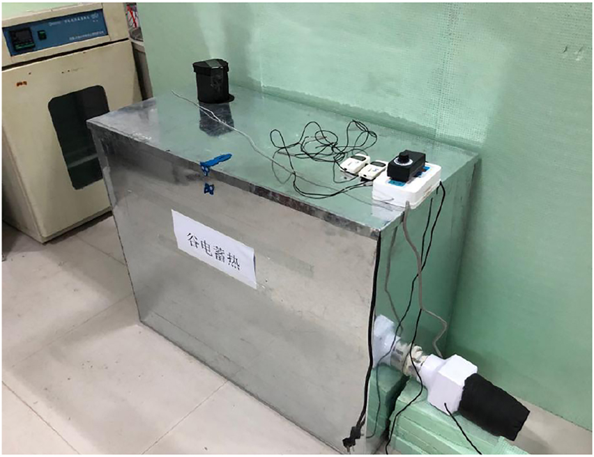
Photo of the air insolated box for electricity energy.
Experimental procedure
The experimental equipment mainly includes temperature measuring instrument, intelligent temperature controlling switch, and automatic data acquisition system. The experimental procedures are as follows:
Heat storage.
From 19:30 in the evening till 8:00 in the morning of the next day, the electric heater is switched on and controlled through the intelligent temperature controlling the switch, and the temperature in the insolated box is kept within 54 and 55 °C.
Heat release.
Turn off the electric heater at 8:00 am the next morning, and turn on the switches of the blower, the air inlet temperature detector and the air outlet temperature detector to collect temperature data. The outlet temperature is recorded once every 30 s, and the inlet temperature is recorded once every 30 min.
Analysis of heat storage performance of equipment
The heat release lasts 11.5 h during the day, which releases the heat stored within the equipment by the composite PCM, the amount of heat release Qsr can be estimated by using Eq. (2),
in which, TS is the phase transition temperature of composite PCM, here Ts = 36 °C; T1 is the maximum working temperature of energy storage electric heater, 72 °C; T2 is the minimum working temperature of energy storage electric heater, here T2 = 25 °C; m is the mass quantity of composite PCM, m = 43.2 kg; L is the latent heat of phase the composite material, 178.02 kJ/kg (Farid et al. 2004; Jankowski and Mccluskey 2013); C1 is the specific heat capacity of the heat storage material in liquid state, 1.94 kJ/kg·°C (Farid et al. 2004; Jankowski and Mccluskey 2013); Cs is the specific heat capacity of the heat storage material in solid state, Cs = 1.69 kJ/kg·°C (Farid et al. 2004; Jankowski and Mccluskey 2013); ΔT1 = T1 – TS; and ΔTs = TS – T2.
The estimated result of Qsr from Eq. (2) is 11,510.68 KJ.
Additionally, in the actual test, the average temperature of the composite PCM in the heat storage unit is 60.2 °C as the heat storage stops, and the average temperature of the material is 24.6 °C as the heat release stops.
Heat release performance of equipment
In the heat release stage, the heater is turned off, the upper vent and the lower ducted ventilating fan in the insolated box are turned on. Air enters from the upper left and exhausts from the lower right. Therefore, the composite PCM inside the heat storage unit roughly radiates heat in one direction during the heat release process, and the air is fully heated, the air temperature change at the air inlet and the air temperature at the exhaust outlet are as shown in Figures 8 and 9, respectively.

Temperature change of inlet air with respect to time.
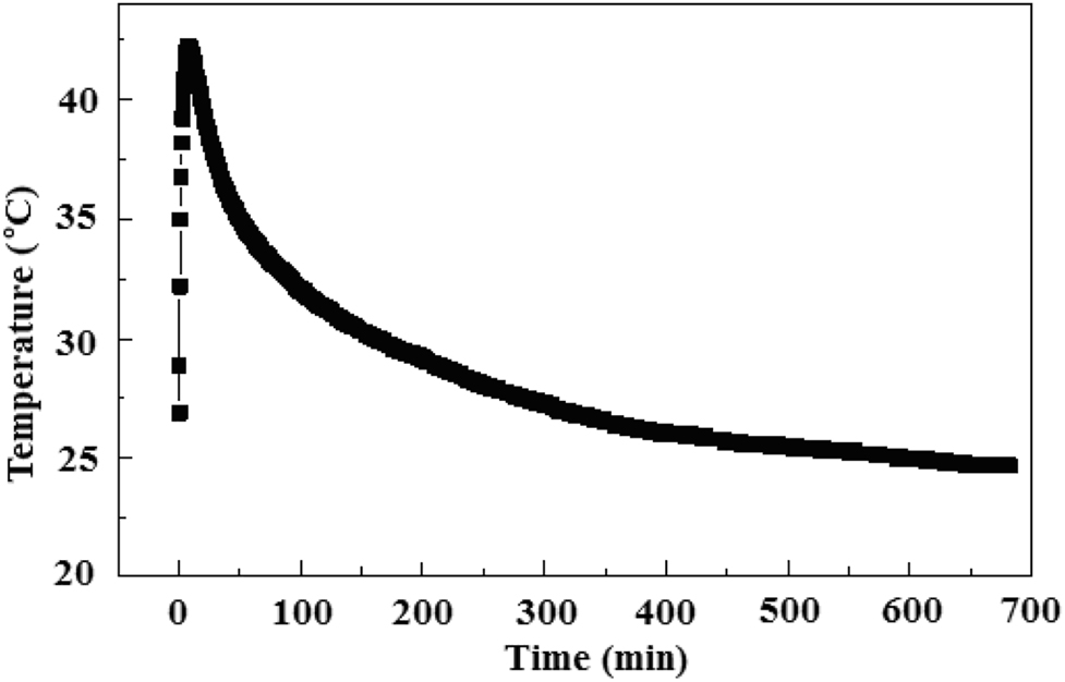
Temperature change of outlet air with respect to time.
The temperature of the inlet port (Figure 8) is counted every 5 min, and the average inlet temperature is 19.4 °C. In the initial stage, since the inlet port has just been opened, there is hot air flow in the heat storage device, which causes the temperature to be unstable. After the equipment is operating stably, the air temperature at the air inlet becomes stabile gradually. The temperature of the air outlet (Figure 9) is counted every 0.5 min. When the heat is released, it takes a moment for the equipment to run to send out the heated air, so the temperature jumps to a higher value suddenly as is shown in Figure 9. It can be seen from the Figure 9 that after 11 h of operation the equipment can still be maintained at about 25 °C.
The instant increment of air heat output during daytime from insulated box can be assessed by Eq. (3),
The integral of Eq. (3) could give the total heat release in the whole daytime,
In Eqs. (3) and (4), Qa is the output heat from insulated box during the daytime (11.5 h); Va is flow rate of air of the ducted exhaust fan, here Va = 55 m3/h; ρa is air density, here ρa = 1.29 kg/m3; T is the total time of heat release, T = 11.5 h; Ca is the specific heat capacity of air, here Ca = 1.4 kJ/kg·°C; ΔT is the difference between the instantaneous temperature of the outlet and the instantaneous temperature of the inlet.
Finally, the estimated result of Qa is 10,312.94 KJ.
Furthermore, the heat exchange efficiency η of the equipment can be defined as the ratio of the total released heat energy in daytime to the total restored heat energy of the composite PCM in night by Eq. (5),
From the experimental test, the estimated value of η is 89.59%.
It can be seen that the Na2HPO4⋅12H2O-based composite PCM and the thermal storage equipment have promising heat storage performance.
Conclusions
Thermal storage equipment with Na2HPO4⋅12H2O-based composite PCM is designed so as to perform the heat storage and supply continuous service for succeeding application. Through the study of the heat storage behavior of the equipment, the following conclusions can be obtained,
The composite PCM composing of Na2HPO4·12H2O and Na3PO4⋅12H2O at the ratio of 7:3 has good heat storage performance with solidification temperature of 33.4 °C and supercooling degree of 2.6 °C.
It takes about 5.5 h to melt the composite PCM in nighttime by electric heater to store thermal energy.
The self – designed “peak load shifting” insolated box for heat storage of electricity energy has promising performance with the energy exchange efficiency of 89.59%.
Funding source: Shaanxi Province Key Research Fund
Award Identifier / Grant number: 2019GY-157
-
Author contributions: All the authors have accepted responsibility for the entire content of this submitted manuscript and approved submission.
-
Research funding: This article was funded by Shaanxi Province Key Research Fund under the grant number 2019GY-157 and Wisteria Scientific Research Cooperation Special Project of Northwest University, which is hereby acknowledged.
-
Conflict of interest statement: The authors declare no conflicts of interest regarding this article.
References
Ahmet, S. 2003. “Thermal Characteristics of a Eutectic Mixture of Myristic and Palmitic Acids as Phase Change Material for Heating Applications.” Applied Thermal Engineering 23 (8): 1005–17, https://doi.org/10.1016/S1359-4311(03)00031-0.Search in Google Scholar
Ahmet, S., and K. Kamil. 2001. “Thermal Performance of Myristic Acid as a Phase Change Material for Energy Storage Application.” Renewable Energy 24 (2): 303–17, https://doi.org/10.1016/S0960-1481(00)00167-1.Search in Google Scholar
Ahmet, S., and K. Kamil. 2006. “Thermal Energy Storage Characteristics of Myristic and Stearic Acids Eutectic Mixture for Low Temperature Heating Applications.” Chinese Journal of Chemical Engineering 14 (2): 270–5, https://doi.org/10.1016/S1004-9541(06)60070-0.Search in Google Scholar
Brousseau, P., and M. Lacroix. 1996. “Study of the Performance of a Multi-Layer PCM Storage Unit.” Energy Conversion and Management 37: 599–609, https://doi.org/10.1016/0196-8904(95)00207-3.Search in Google Scholar
Farid, M. M., A. M. Khudhair, S. A. K. Razack, and S. Al-Hallaj. 2004. “A Review on Phase Change Energy Storage: Materials and Applications.” Energy Conversion and Management 45 (9): 1597–615, https://doi.org/10.1016/j.enconman.2003.09.015.Search in Google Scholar
Gschwander, P., and H. Henning. 2005. “Micro-Encapsulated Paraffin in Phase-Change Slurries.” Solar Energy Materials and Solar Cells 89 (2–3): 307–15, https://doi.org/10.1016/j.solmat.2004.12.008.Search in Google Scholar
Gulseren, B., and S. Ahmet. 2003. “Phase Change and Heat Transfer Characteristics of a Eutectic Mixture of Palmitic and Atearic Acids as PCM in a Latent Heat Storage System.” Energy Conversion and Management 44 (20): 3227–64, https://doi.org/10.1016/S0196-8904(03)00104-3.Search in Google Scholar
Ha, K. 2020. “Innovative Blade Trailing Edge Flap Design Concept Using Flexible Torsion Bar and Worm Drive.” High Tech and Innovation Journal l1 (3): 101–6, https://doi.org/10.28991/HIJ-2020-01-03-01.Search in Google Scholar
Halford, C. K., and R. F. Boehm. 2007. “Modeling of Phase Change Material Peak Load Shifting.” Energy and Buildings 39: 298–305, https://doi.org/10.1016/j.enbuild.2006.07.005.Search in Google Scholar
Hiran, S., T. S. Saiton, M. Oya, and M. Yamazaki. 2015. “Temperature Dependence of Thermophysical Properties of Disodium Hydrogenphosphate Dodecahydrate.” Journal of Thermophysics and Heat Transfer 15 (3): 340–6, https://doi.org/10.2514/2.6613.Search in Google Scholar
Hou, Y., F. Xu, and W. Cheng. 2008. “Overall Optimal Dynamic Investment Strategy for Renewable Energy Substitution.” Business Research 50 (5): 67–72, https://doi.org/10.13902/j.cnki.syyj.2008.05.021.Search in Google Scholar
Huang, J., T. Wang, P. Zhu, and J. Xiao. 2013. “Preparation, Characterization, and Thermal Properties of the Microencapsulation of a Hydrated Salt as Phase Change Energy Storage Materials.” Thermochimica Acta 557 (7): 1–6, https://doi.org/10.1016/j.tca.2013.01.019.Search in Google Scholar
Jankowski, N. R., and F. P. Mccluskey. 2013. “A Review of Phase Change Materials for Vehicle Component Thermal Buffering.” Applied Energy 113 (113): 1525–61, https://doi.org/10.1016/j.apenergy.2013.08.026.Search in Google Scholar
Jin, H., J. Liu, M. Zheng, H. P. Teng, and L. P. Wei. 2019. “Application of Phase-Change Material in Solar Hot-Water System.” Energy 172 (1): 12–8, https://doi.org/10.1680/jener.18.00010.Search in Google Scholar
Kadir, T. B., S. Ahmet, T. Sefa, E. Gazanfer, and K. Kamil. 2004. “Lauric and Palmitic Acids Eutectic Mixture as Latent Heat Storage Material for Low Temperature Heating Applications.” Energy 30 (5): 677–92, https://doi.org/10.1016/j.energy.2004.05.017.Search in Google Scholar
Kibaarae, S., D. K. Murage, P. Musau, and M. J. Saulo. 2020. “Comparative Analysis of Implementation of Solar PV Systems Using the Advanced SPECA Modelling Tool and HOMER Software: Kenyan Scenario.” HighTech and Innovation Journal 1 (1): 8–20, https://doi.org/10.28991/HIJ-2020-01-01-02.Search in Google Scholar
Kıvanç, T., and Y. Wall. 2019. “Trombe Wall Application with Heat Storage Tank.” Civil Engineering Journal 5 (7): 1477–89, https://doi.org/10.28991/cej-2019-03091346.Search in Google Scholar
Lan, X. Z., Z. C. Tan, Q. Shi, and Z. H. Gao. 2009. “Performance Heat Capacity and Heat of Fusion.” Journal of Thermal Analysis and Calorimetry 96 (3): 1035–40, https://doi.org/10.1016/j.tca.2007.04.008.Search in Google Scholar
Li, H., J. Cheng, and J. He. 2013. “Simulation of Phase Transition Characteristics of Phase Change Gypsum Board in Hot Summer and Cold Winter Area.” Journal of Nanjing University of Technology (Natural Science Edition): Natural Science Edition 35 (4): 115–20, https://doi.org/10.3969/j.issn.1671-7627.2013.04.024.Search in Google Scholar
Mazzeo, D., and G. Oliveti. 2017. “Parametric Study and Approximation of the Exact Analytical Solution of the Stefan Problem in a Finite PCM Layer in a Steady Periodic Regime.” International Communications in Heat and Mass Transfer 84: 49–65. https://doi.org/10.1016/j.icheatmasstransfer.2017.03.013.Search in Google Scholar
Mazzeo, D., and G. Oliveti. 2018. “Thermal Field and Heat Storage in a Cyclic Phase Change Process Caused by Several Moving Melting and Solidification Interfaces in the Layer.” International Journal of Thermal Sciences 129: 462–88. https://doi.org/10.1016/j.ijthermalsci.2017.12.026.Search in Google Scholar
Mazzeo, D., G. Oliveti, A. de Gracia, J. Coma, A. Sole, and L. F. Cabeza. 2017. “Experimental Validation of the Exact Analytical Solution to the Steady Periodic Heat Transfer Problem in a PCM Layer.” Energy 140: 1131–47. https://doi.org/10.1016/j.energy.2017.08.045.Search in Google Scholar
Qerimi, D., C. Dimitrieska, S. Vasilevska, and A. A. Rrecaj. 2020. “Modeling of the Solar Thermal Energy Use in Urban Areas.” Civil Engineering Journal 6 (7): 1349–67, https://doi.org/10.28991/cej-2020-03091553.Search in Google Scholar
Schossig, H., S. Gschwander, and T. Haussmann. 2005. “Micro-encapsulated Phase-Change Materials Integrated into Construction Materials.” Solar Energy Materials and Solar Cells 89 (2–3): 297–306, https://doi.org/10.1016/j.solmat.2005.01.017.Search in Google Scholar
Wahba, S., B. Kamil, K. Nassar, and A. Abdelsalam. 2019. “Green Envelop Impact on Reducing Air Temperature and Enhancing Outdoor Thermal Comfort in Arid Climates.” Civil Engineering Journal 5 (5): 1124–35, https://doi.org/10.28991/cej-2019-03091317.Search in Google Scholar
Walsh, B. P., S. N. Murray, and D. T. J. O’Sullivan. 2013. “Free-cooling Thermal Energy Storage Using Phase Change Materials in an Evaporative Cooling System.” Applied Thermal Engineering 59 (1–2): 618–23, https://doi.org/10.1016/j.applthermaleng.2013.06.008.Search in Google Scholar
Xu, B., and Z. Li. 2014. “Performance of Novel Thermal Energy Storage Engineered Cementations Composites Incorporating a Paraffin/diatomite Composite Phase Change Material.” Applied Energy 121 (5): 144–8, https://doi.org/10.1016/j.apenergy.2014.02.007.Search in Google Scholar
Xu, J., and Z. Li. 2019. “The Feasibility of Applying Energy Storage Electric Heating Technology Products in Guanzhong Area.” Resource Conservation and Environmental Protection Issue 1: 1–8, https://doi.org/10.16317/j.cnki.12-1377/x.2019.10.035.Search in Google Scholar
Zheng, M., J. Liu, and H. Jin. 2019. “Improvement of Thermal-Storage Performance of Industrial-Grade Disodium Hydrogen Phosphate.” Energy 172 (3): 115–21, https://doi.org/10.1680/jener.18.00012.Search in Google Scholar
Zheng, M., C. Xie, J. Liu, and H. Jin. 2019. “Composite Hydrate Salt Na2HPO4·12H2O – Na2SO4·10H2O and its Thermal Storage Properties.” Emerging Materials Research 8 (1): 68–76, https://doi.org/10.1680/jemmr.18.00042.Search in Google Scholar
© 2022 Walter de Gruyter GmbH, Berlin/Boston
Articles in the same Issue
- Frontmatter
- Review
- A comprehensive review on electric vehicles: charging and control techniques, electric vehicle-grid integration
- Research Articles
- Evaluation of parameters influencing the performance of photovoltaic-thermoelectric (PV-TE) hybrid system
- Dispatchable power supply from beam down solar point concentrator coupled to thermal energy storage and a Stirling engine
- Modelling, design and parametric analysis of a levitation based energy harvester
- Performance optimization of flywheel using experimental design approach
- Assessment and optimization of photovoltaic systems at the University Ibn Tofail according to the new law on renewable energy in Morocco using HOMER Pro
- Optimizing hybrid power system at highest sustainability
- Preparation of Na2HPO4⋅12H2O-based composite PCM and its application in air insulated box
- The efficiency of linear electromagnetic vibration-based energy harvester at resistive, capacitive and inductive loads
- A numerical investigation of optimum angles for solar energy receivers in the eastern part of Algeria
- Experimental investigation of soiling effects on the photovoltaic modules energy generation
- Frequency domain analysis of a piezoelectric energy harvester with impedance matching network