Severity of corrosion under insulation (CUI) to structures and strategies to detect it
-
Elsadig O. Eltai
Elsadig O. Eltai holds a PhD from the University of Manchester (title of thesis:
Epoxy coated steel pipeline under cathodic protection ). Dr. Eltai has conducted successful research in different areas includes coatings, cathodic protection, welding, composites and pipeline. He is actively engaged with industry, trying to help them solve the challenges they are facing. Dr. Eltai has published more than 20 papers in high-impact factor journals. He is also a reviewer of many respected journals. ,
Farayi Musharavati
,
Farayi Musharavati
Farayi Musharavati is an associate professor in the Mechanical and Industrial Engineering Department, Qatar University. His research interests include intelligent manufacturing, materials engineering and design, renewable energy, sustainability, life cycle assessment, simulation modeling, applications of optimization techniques as well as engineering applications in biomedical research, desalination, biomedical applications and nano coating. He has published more than 50 technical papers.
El-sadig Mahdi has vast experience in research in materials science and engineering. He is active in different research areas such as corrosion, fatigue analysis of conventional materials, mechanical design, failure analysis, composite materials and finite element. He supervised Bachelor’s, Master’s and PhD theses. He has published over 200 technical papers. His current research is on materials for energy, corrosion-erosion and optimizing of advanced materials for the oil and gas industry.

Abstract
This review paper considers the research conducted in the past 30 years in the field of corrosion under insulation (CUI). CUI is a significant challenge in many industries for reasons of high cost and risk because it proceeds undetected under insulation. CUI is an unavoidable problem which may potentially cause personnel injury or even fatalities. Presently, CUI counts for as much as 40 to 60% of pipeline-repairing cost. The use of coating under the insulation has been shown very efficient in the mitigation of CUI. Moisture and ion penetration, particularly chlorides, through the insulation and coating may produce stress corrosion cracking of austenitic stainless steels. The process of applying insulating materials on metal surfaces and the precautions that need to be taken are explained. Beside visual inspection, techniques such as neutron backscatter, capacitive imaging and pulsed eddy current can be used to detect the presence of CUI. The strength and limitations of the available commercial detection techniques are evaluated. A comprehensive list of industrial standards dealing with CUI is provided.
1 Introduction
Any discussion concerning the occurrence of aqueous metallic corrosion should take into account four different elements: the anodic and cathodic reactions, the electrolyte, and the metallic conduction (Mayne, 1959). To slow down the corrosion process, interruption of one or more of these elements should be considered. Nowadays, many anti-corrosion measures are being used. However, it is not possible to completely stop corrosion; instead, it can only be slowed down. Consequently, companies around the globe are struggling to find permanent solutions in order to avoid catastrophic failures and reduce the high cost. One of the most severe types of corrosion is corrosion under insulation (CUI), which is defined as an electrochemical degradation of an alloy or metal under the insulation. CUI cannot be detected by surface measurement techniques because it is hidden under the insulation or cladding. In the industry, it is common practice to wrap pipelines with insulating material in order to protect them against external or general environmental issues, to protect personnel working around the structures, to minimize heat losses and to maintain temperatures for the efficient operation of the process (Uygunoglu & Kecebas, 2011; Kayfeci et al., 2013; Ristimaki et al., 2013). CUI is widely known as one of the worst industrial problems because it is hard to be detected and because of the high-cost. Critical areas that provide pathways for moisture and other corrosive species are joints between the insulation, as in Figure 1. The insulation material may contribute to CUI by providing an annular space for the retention or accumulation of water, with access to oxygen. Therefore, it is recommended to increase the thickness of the insulation at these areas in order to reduce the likelihood of water and other corrosive species ingress through these joints. The presence of defects or damages on the insulation can also provide a pathway for water and ions to reach the metal surface and cause corrosion.
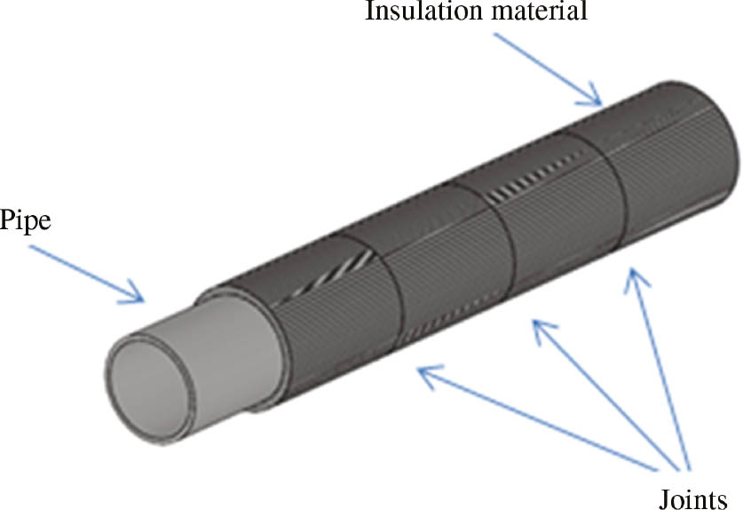
Wrapped pipeline.
CUI can take different forms. It can be considered localized corrosion because it initially takes place when moisture penetrates the insulation material and reaches the metal surface. It can then spread below the insulation to other parts of the metal surface, which means that at some point it could be general corrosion. CUI can also take the form of pitting corrosion, stress corrosion cracking (SCC) and, in some cases, galvanic corrosion, where wet insulation that contains salts may allow current to pass between different metals, as shown by Mitchell (1988). Throughout the oil and gas industry, the early detection of pipeline corrosion, in general, and CUI, particularly, plays a vital role in managing the integrity of the pipes. The areas most susceptible to CUI are pipe bends and welds because these areas are challenging to be perfectly wrapped. Also, they are mechanically weak and have less corrosion resistance (Dimitris & Theodora, 2017; Han et al., 2018; He et al., 2019). To give the reader more insight into the standards and code of practices related to CUI, a comprehensive list of industrial standards dealing with CUI is summarized in Table 1.
Short description of the standards referred to in this paper.
| Standard | Description |
|---|---|
| API-570. Piping Inspection Code: In-service Inspection, Rating, Repair, and Alteration of Piping Systems, 2016 | This recommendation was developed for the refining and chemical process industries; it also is recommended to be used for any piping system It should not be used as a substitute for the original construction requirements governing a piping system before it is placed-in-service, nor shall it be used in conflict with any prevailing regulatory requirements |
| API-RP-581. Risk-Based Inspection Technologies, 2008 | API-RP-581 provides guidance mainly for developing RBI programs on fixed equipment in refining, petrochemical and chemical process plants and oil and gas production facilities The intent is for API-RP-581 to introduce the principles and present minimum general guidelines for RBI while this recommended practice provides quantitative calculation methods to determine an inspection plan |
| API-583. Corrosion under insulation and fireproofing, 1st ed, 2014 | This practice covers the design, maintenance, inspection and mitigation practices to address both the external CUI and corrosion under fireproofing The practice discusses the external corrosion of carbon and low alloy steels under insulation and fireproofing and the external chloride stress corrosion cracking of austenitic and duplex stainless steels under insulation. However, it does not cover atmospheric corrosion or corrosion at uninsulated pipe supports but does discuss corrosion at insulated pipe supports |
| ASTM-C795-08. Standard Specification for Thermal Insulation for Use in Contact with Austenitic Stainless Steel, 2018 | This specification covers non-metallic thermal insulation for use in contact with austenitic stainless steel piping and equipment. In addition to meeting the requirements specified in their individual material specifications, issued under the jurisdiction of ASTM Committee C16, these insulations must pass the preproduction test requirements of Test Method C692 for stress corrosion effects on austenitic stainless steel and the confirming quality control, chemical requirements, when tested in accordance with the Test Methods C871 |
| ASTM-C692-13. Standard Test Method for Evaluating the Influence of Thermal Insulations on External Stress Corrosion Cracking Tendency of Austenitic Stainless Steel, 2018 | This standard test method covers two procedures for the laboratory evaluation of thermal insulation materials to determine whether they contribute to external stress corrosion cracking (ESCC) of austenitic stainless steel due to soluble chlorides within the insulation. This laboratory procedure is not intended to cover all of the possible field conditions that contribute to ESCC The procedures in this test method consist of using a specimen of insulation to conduct distilled (or deionized) water by wicking or dripping to an outside surface, through the insulation, to a hot inner surface of stressed Type 304 stainless steel for 28 days. If leachable chlorides are present, they are carried along with the water and concentrated at the hot surface by evaporation in much the same way as has been experienced in actual industrial process situations |
| ASTM-C871-18. Standard Test Methods for Chemical Analysis of Thermal Insulation Materials for Leachable Chloride, Fluoride, Silicate, and Sodium Ions, 2018 | This practice covers the laboratory procedures for the determination of water-leachable chloride, fluoride, silicate and sodium ions in thermal insulation materials in the parts per million range Insulation specimens are leached for 30 min in boiling water. Tests to determine quantitatively chloride, fluoride, silicate and sodium ions are performed on aliquots of the filtered leachate solution |
| ASTM-G189. Guide for Laboratory Simulation of Corrosion Under Insulation, 2013 | This guide covers the simulation of CUI, including both general and localized attack, on insulated specimens cut from pipe sections exposed to a corrosive environment usually at elevated temperature. It describes a CUI exposure apparatus (after this referred to as a CUI-Cell), preparation of specimens, simulation procedures for isothermal or cyclic temperature, or both, and wet/dry conditions, which are parameters that need to be monitored during the simulation and the classification of simulation type The CUI-Cell consists of three- to six-ring specimens separated by non-conductive spacers and held together by two blind flanged pipe sections, one on each end |
| DNV-RP-G101 practice. Risk-based inspection of offshore topsides static mechanical equipment, 2010 | The objective of this recommended practice is to describe a method for establishing and maintaining an RBI plan for offshore pressure systems. It provides guidelines and recommendations which can be used to customize methods and working procedures that support the inspection planning process. It is divided into two parts covering (1) an introduction to RBI and (2) recommendations for a working process This recommended practice is primarily intended to be used for the planning of in-service inspection for offshore topsides static mechanical pressure systems when considering failures by loss of containment of the pressure envelope. Failure modes, such as failure to operate on demand, leakage through gaskets, flanged connections, valve stem packing, together with valve passing and tube clogging, are not addressed in this document |
| NACE-SP0198. The Control of Corrosion Under Thermal Insulation and Fireproofing Materials – A Systems Approach, 2012 | The practice provides current technology and industry practices for mitigating corrosion under thermal insulation and fireproofing materials. It adopts a systems approach. Contains sections on corrosion mechanisms, mechanical design, protective coatings, insulation materials and inspection and maintenance In this standard, the term equipment includes all objects in a facility with external metal surfaces that are insulated or fireproofed and subject to corrosion |
| NORSOK Standard M-501. Surface preparation and protective coating, 2012 | This standard aims to obtain a coating system, which ensures: – optimal protection of the installation with a minimum need for maintenance – that the coating system is maintenance friendly – that the coating system is application friendly – that health, safety and environmental impacts are evaluated and documented This standard is not applicable to pipelines and pipeline risers. It gives the requirements for the selection of coating materials, surface preparation, application procedures and inspection for protective coatings to be applied during the construction and installation of offshore installations and associated facilities It covers both paints, metallic coatings and application of spray-on passive fire-protective coatings |
| NORSOK Standard R-004. Piping and equipment insulation. Rev 2, 1999 | The standard covers the minimum requirements for thermal, acoustic, personnel protection, fire protection and pipe penetration insulation of pipework, equipment, vessels, tanks, valves, flanges, etc., for offshore/onshore installations It does not cover refractory or insulation of heating, ventilation, and air conditioning-related items |
The API-570 (2016) (Table 1) listed the areas that are more susceptible to CUI, which includes hangers, fittings, ladders, platforms, areas exposed to mist overspray from cooling water towers, areas exposed to steam vents, areas exposed to deluge systems and areas subject to process spills, ingress of moisture or acid vapors, as well as carbon steel piping systems, including those insulated for personnel protection, operating between 25°F and 250°F. CUI is particularly aggressive where operating temperatures cause frequent condensation and re-evaporation of atmospheric moisture. Carbon steel piping systems which operate intermittently in service between 150°F and 400°F (60°C and 204°C): deadlegs and attachments that protrude from insulated piping and operate at a temperature different than the active line, austenitic stainless steel piping systems that operate between 150°F and 400°F (60°C and 204°C). These systems in the presence of mechanical stress are susceptible to chloride SCC. Moreover, vibrating piping systems tend to cause damage to insulation jacketing, providing a pathway for water ingress. It is reported that many environments cause CUI to increase; this includes, but not limited to, the marine environment, humid environment, hot environment and contaminants from the atmosphere, particularly in heavy industrial places. Contaminants can also come from the insulation itself. Environmental conditions may cause wetting and drying cycles, which are well known to have a detrimental impact on CUI.
It is well known that intermittent wet-dry cycles accelerate the rate of CUI. During the wetting and drying cycles, diffusion of chloride and other ions through the insulation material is governed by several factors: first is the sequence of wetting and drying as well as the duration. Specifically, the degree of dryness plays a vital role in the corrosion process. Drying to a greater depth followed by wetting allows chloride ions to go deeper through the insulation, thus speeding up the penetration of chloride ions, inflicting corrosion. Soeren and Rasmussen (2017) conducted cyclic testing of six different insulation materials with one dry/wet phase for each cycle. The authors concluded that closed-cell insulation and semi closed-cell insulation materials resulted in significant surface areas being exposed to corrosion and, consequently, higher corrosion rate, which was attributed to entrapment of water on the metal surface. On the other hand, fully water vapor permeable material gives way for water to scape leading to fast drying and low corrosion rate. It is significant to select a suitable insulation material that allows water to drain in case it accumulates beneath the insulation material. There are lots of ways for water to enter the insulation, such as rainfall or from condensation. The chemistry and properties of the insulation also have an impact on CUI by absorbing water from the surrounding environment, leading to the occurrence of CUI. Furthermore, it is possible that chemicals within the insulation itself, such as chlorides and sulfates, may leak into the electrolyte and speed up the corrosion process. This emphasizes the importance of proper insulation design, systematic inspection and regular maintenance as illustrated by Poitanabuntoeng et al. (2017).
The heat which comes from the atmosphere or the fluid inside the pipe can also accelerate the rate of CUI by releasing contaminants to condensed water, leading to a very corrosive environment. In hot areas, temperature can damage the insulation material and affects its mechanical and permeability characteristics. If service temperature exceeds 121°C, most water evaporates and condenses at the edges of the insulation material, leading to the dissolution of corrosive species and eventually corroding the outer jacket. Evaporation of rain and water used for process water or firefighting from the insulation leads to a high concentration of corrosive ions, thus increasing the rate of CUI as illustrated by ASTM-C795–08 (2018) (Table 1).
Most metals and alloys can be affected by CUI, including carbon steel, austenitic stainless and aluminum. 316 and 304 Stainless steels are prone to SCC, particularly in the presence of chloride ions, which can easily penetrate through the insulation material. In such an environment, CUI can progress rapidly in these grades. Chloride-induced SCC can severely damage austenitic stainless steels, but it does not affect carbon steel. Because of the excellent anti-corrosion and desirable mechanical properties of austenitic stainless steel, it is widely used in chemical, petrochemical, nuclear and other industries; they also have excellent resistance to heat. In the presence of certain levels of chlorides and fluorides under specific stress and environmental conditions, SCC may take place on austenitic stainless steel. However, the susceptibility of austenitic stainless steel to SCC in a warm and oxygenated environment at certain chloride levels limits their use in many industries because failures that are caused by SCC can be catastrophic. Therefore, insulated austenitic steels should be given extra care by maintaining regular checks, choosing impermeable insulation materials to chloride/fluoride ions and monitoring the level of corrosive species at all time as illustrated by Sedriks (1992), ASTM-C692 (2018) (Table 1), Delaunois et al. (2016) and ASTM-C871 (2018) (Table 1). Carbon steel and low alloy steel can be severely affected by CUI; despite this, they are widely used in the construction of equipment, tanks and piping in the oil/gas industries because they are cheap compared to stainless steel and their corrosion characteristics are well understood (Shong, 2017). Figure 2 shows CUI on an uncoated carbon steel pipe due to the penetration of water and different ions through the insulation material (Eltai et al., 2016).
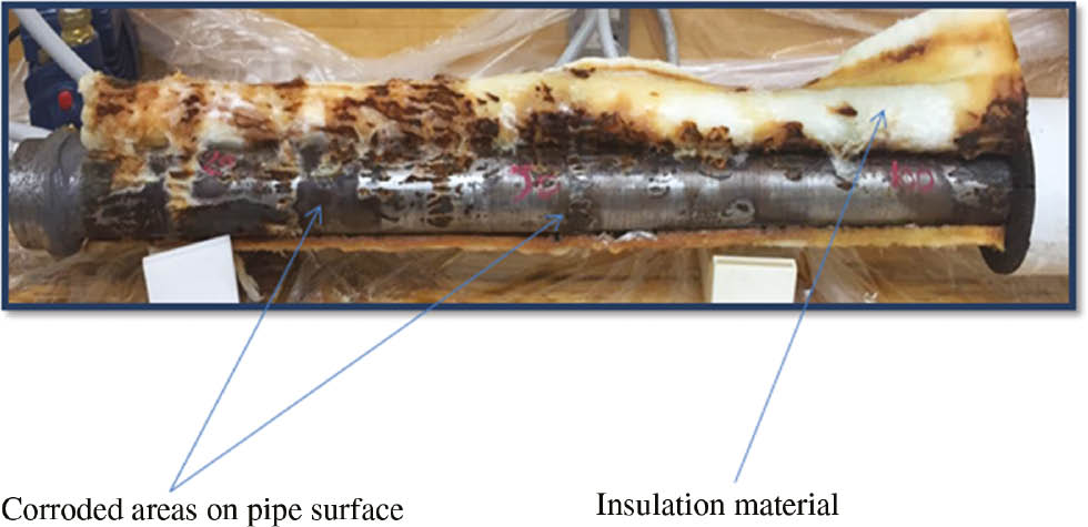
CUI on insulated uncoated steel pipe.
It is significant to give great attention to the process of applying the insulation on the metal surface because the performance of the insulation during service depends on many factors such as proper insulation application. All piping and other structures should be insulated according to insulation class, operation temperature and thickness of the insulation. Moreover, the insulation process should be conducted by qualified personnel. The insulation materials and the external jacketing shall be installed in such a way that they stop water from entering the insulation material or between the insulation and the pipe/equipment surface during service life. The external jacket can be defined as an exterior covering or casing, such as the insulating cover of the combustion engine or a boiler, etc. The surfaces under the insulation, whether it is coated or not, shall be clean and dry. If the metal surface is coated, a mechanical completion certificate for the coating has to be issued first before commencement of work. Surfaces to be insulated shall be treated in accordance with NORSOK-M-501 (2012) (Table 1). It is possible that welds and joints can be left uninsulated to allow inspection during testing. NORSOK-R-004 (1999) (Table 1) recommended that the packing gland shall be left accessible when insulating valves. The objectives of this review article are to highlight the severity of CUI to different structures and to discuss the various techniques that are being used to detect it. Moreover, it is meant to bridge the knowledge gap and discuss areas that need further research in order to avoid severe consequences of pipeline and other structure failures, which affect our environment, economy and the safety of the people at large.
2 Severity of CUI to structures
It is widely accepted that CUI is a serious problem that severely affects different structures. The effects include, but are not limited to, health, asset integrity, safety, production losses and the environment (Caines et al., 2013). Corrosion is a widespread problem in many industries, particularly in oil and gas, counting for approximately 80% of all pipe maintenance costs. Based on a study carried out between 1999 and 2001, the direct cost of corrosion in the United States alone was estimated to be 276 billion dollars a year, which is equivalent to 3% of the gross domestic product. Wilds (2017) and Winnik (2003) reported that between 40% and 60% of pipeline repairing costs in the oil and gas industry are related to CUI. A corrosive environment can be formed between the insulation and the metal. However, it is not possible to see the corrosion; therefore, any possible catastrophic damage more likely will not be discovered until a serious event takes place, potentially causing injury or even fatality in addition to partial or full process shutdown. Wolf (1995) reported several industrial incident failures where the main cause was attributed to selection of poor materials. In the open literature, many failure cases due to CUI were reported: the first one was a storage tank that contained hot asphalt. Extensive corrosion was revealed after the cladding and insulation were blown away; in fact, corrosion had not been anticipated because there was no evidence of any external corrosion. Because of the significant metal loss, it was decided that the tank should be replaced. The second failure case was an insulated coated pipe operating at a temperature below 93°C; the failure was attributed to the incorrect specification of the coating used (Wilds, 2017). Geary (2013) investigated the failure in a carbon steel refinery line; the main cause of failure was found to be CUI. These failures highlighted the importance of proper material selection.
Eltai et al. (2016) investigated the corrosion behavior of an insulated uncoated mild steel pipe that was exposed to seawater at different drop rates (10, 30 and 50 drops/min) at ambient temperature. Two different insulators were used: harsh environment silica and cellular glass insulations. The authors conducted different experimental strategies as well as visual inspection and scanning electron microscopy (SEM). It was noted that the uncoated pipe under the insulation materials was corroded due to the penetration of water and other corrosive species through the insulation material. The extent of corrosion on the metal surface was found to be different from one area to another, which was attributed to the frequency of water drops and the number of corrosive species that penetrated through the insulation and reached the metal surface. The authors concluded that it is necessary to regularly inspect the status of the pipe and the insulation material. It was also revealed that the severity of the CUI is proportional to the drop rate.
3 Impact of insulation materials and coatings on the corrosion process
Williams and Evans (2010) investigated the impact of insulation materials on corrosion. The authors discussed different methods to combat CUI. They claimed that a good designer of industrial equipment and piping has three main weapons to fight CUI: high-quality coating, a weather barrier jacketing and the choice of the insulation material. The authors aimed at exploring the influence of different materials on CUI. They tested eight different insulation materials. As anticipated, the best material of choice was Cryogel. The paper validated that water-absorbent insulation materials promote CUI, while water-repellent insulation materials reduce the occurrence of CUI. The study conducted by Erturk (2016) was focused on the impact of insulation thickness on the lifetime cost of steel pipelines that have different diameters (50, 100, 200, 400, 600, 800 and 1000 mm) using the life cycle cost analysis over a 10-year lifetimes. The insulation materials considered by the author were rock wool, extruded polystyrene and expanded polystyrene. The author found that the optimum insulation thickness varies between 5.18 and 15.8 cm. In 1989, the National Association of Corrosion Engineers (NACE) published their first document on CUI, NACE-6H189 (1989) (Table 1). A second document was published by NACE in 1998 and revised in 2004, NACE-SP0198 (2017) (Table 1). The document emphasized the importance of a systematic approach that involves the design, the installation, the maintenance and the inspection of the structure. It was concluded that a general solution to combat CUI is to use a protective coating under the insulation material. The document also discussed different temperature ranges and highlighted the importance of surface preparation and profile requirement for different coating systems. It went further and suggested primers and topcoats for different coating systems that can be used under the insulation. The application of coatings on pipe surfaces under the insulation material is widely used in the industry because it helps reduce CUI by slowing water uptake and the permeation of corrosive species toward the metal surface. Eltai et al. (2012a,b, 2013, 2016) recommended carefully selecting a high-quality coating to withstand the expected service conditions.
Furthermore, Eltai (2009) discussed the importance of surface preparation and profile requirement for excellent coating adhesion to the metal surface. De Sousa et al. (2007) discussed the interactions and compatibility of polyurethane foams and anticorrosive coatings. The results revealed that a proper selection of a fitting coating is essential to guarantee a stable performance. Miyashita (2017) tested three types of coatings in severe simulated CUI environments (i.e. heat-resistant epoxy coatings, new technology liquid coatings and thermal sprayed aluminum coatings) as typical candidates for CUI prevention. It was found that thermal sprayed coatings and heat-resistant epoxy coatings have higher CUI resistance than the new technology liquid coatings.
The American Society for Testing Materials, ASTM-G189 (2013) (Table 1), summarized and published the methods and standards for CUI tests in which they covered the simulation of two types of CUI (uniform and localized) on insulated specimens cut from pipe sections and exposed to a corrosive environment at an elevated temperature. It described the parameters that are required to be monitored during simulation and the classification of simulation type, which includes a CUI exposure apparatus, which is referred to as a CUI-Cell, preparation method, simulation procedures for isothermal or cyclic temperature and wet/dry conditions. A preliminary study to reduce pipeline corrosion was conducted by Mahdi and Eltai (2018). Steel pipes were wrapped with four layers of carbon fiber-reinforced plastic (CFRP) and glass fiber-reinforced plastic (GFRP) and immersed in sodium chloride solution for 1 year. It was found that the steel pipes that were wrapped with GFRP were corrosion free. However, the pipes that were wrapped with CFRP showed some corrosion, which was attributed to galvanic corrosion. The wrapping of steel pipes with GFRP between the coating and the insulation material could be used as an extra defensive layer to reduce the occurrence of CUI and minimize heat loss.
4 Advance research on CUI
One of the challenges facing the industry is that the structures under insulation are inaccessible. Therefore, it is difficult to keep a record of the corrosion rate, which may lead to unavoidable losses (Xiaokang, 2012). Because of the challenges associated with protection against this type of corrosion, CUI has been the subject of much work over the past three decades. The focus was on finding sophisticated techniques that can detect corrosion or moisture at an earlier stage. Accordingly, plans for inspection and maintenance can be implemented well ahead of the occurrence of any possible failure. Based on Robin (2012), a tremendous amount of research was conducted, but unfortunately, many challenges remain unresolved, and the progress is relatively slow because CUI is a very complicated process and difficult to understand. The biggest challenge is how to detect and locate it without stripping the insulation material from the surface. The following is a historic overview of the development and milestones in the detection of CUI. The use of non-destructive tests (NDT) to detect unseen corrosion is mainly based on the estimation of wall thickness or structural discontinuities (Pollock & Barnhart, 1985). The ASTM (Table 1) reviews the factors that cause CUI. Moreover, it discusses experiences with different insulation types and control measurements. It also highlights the need for an accurate and stable nondestructive method for the detection of CUI. Winnik (2003) discussed the root causes of CUI and compared state-of-the-art corrosion prevention methods. He concluded that strategic planning to predict CUI decreases the impact of corrosion damage and consequently reduces the maintenance costs.
Melchers (2003) published a paper proposing a probabilistic model that is capable of predicting the corrosion rate of fully immersed components in seawater. This was a successful attempt to create a mathematical model that is capable of predicting the corrosion rate of a system. This advance did not assume a timely linear corrosion rate, it rather took into account the change of corrosion mechanism over time and then modeled this using a time differential function to predict the corrosion rate. The same author published a second paper discussing pitting corrosion of mild steel in marine environments. It discussed the influence of seawater temperature on anaerobic corrosive behavior. The gathered data were then used to determine a model for predicting the depth of pitting corrosion (Delahunt, 2003; Melchers, 2004). The American Petroleum Institute published its second generation on risk-based inspection (RBI) method, API-581 (2008) (Table 1). It provided information on the establishment of an inspection program using risk-based models and described general reasons for the occurrence of CUI; it further suggested solutions. Det Norske Veritas, DNV-RP-G101 (2010) (Table 1), published a booklet which recommended practice to establish an RBI method for marine power plants. Different degradation mechanisms and the overall goal of RBI were described. Also, they discussed different screening techniques as well as different approaches for inspection and monitoring.
El-Sayed et al. (2009) studied the corrosion behavior of insulated coated pipeline under cathodic protection (CP), and polyurethane was used as a thermal insulator. CP was applied using a 5-mm zinc wire as a sacrificial anode. The work conducted by Eltai et al. (2012a,b, 2013) and Eltai (2009) showed that the reason for using CP as an anti-corrosion measure is to serve as a backup system to protect any defected areas within the coating or the insulation materials. El-Sayed et al. (2009) proved that thermal insulation cannot provide full protection from corrosion due to the possible presence of defects, which provided access to moisture. It was found that the combination of polyurethane insulation material and CP at −920 mV vs. Cu/CuSO4 provides full protection to the carbon steel pipe. One of the common mistakes of corrosion engineers is that they think that by applying CP to coated or insulated structures, full protection can be achieved all the time, but in reality, this is not right. Eltai (2009), in his PhD thesis, discussed the interactions between epoxy-coated carbon steel and CP in great detail and how they affected each other. Likewise the coating, insulation can affect CP by shielding the CP current and stopping it from entering the metal surface. Eltai et al. (2012a,b, 2013) and Eltai (2009) showed that CP can push more water toward the metal surface, leading to more corrosion. The application of high CP current causes the coating to disbond and accelerates the penetration of water through the insulation; consequently, more corrosion will take place. This highlighted the importance of good coating, insulation and CP system designs. Wetting the insulation may help the CP current to reach the metal surface. However, it can harm the system and cause corrosion. Moreover, the wetness of the insulation materials can lead to the acceleration of CUI (Soeren & Rasmussen, 2017). The CP system has some limitations, e.g. it does not work with very-high-resistant coating or insulation because CP current cannot reach the metal surface. Furthermore, if the coating disbonded or the insulation is swallowed, the distance between the metal surface and the coatings/insulation materials would increase, leading to shielding of the CP current (Yin et al., 2018).
Caines et al. (2013) discussed the lack of research in the field of CUI in harsh marine environments. The group described pitting corrosion as the most common type of localized corrosion. They highlighted a knowledge gap in the field of pitting corrosion and its mechanism. A second paper by Caines et al. (2015) aimed to find a model that is capable of accurately predicting CUI and was based on the preliminary work of Melchers (2003). The group selected the isle of Newfoundland in Canada as the location for their field test; this area has a marine environment that is fitting for a CUI test. They proposed three stages of tests. Stage 1 is a field test to gather long-term CUI data; this stage should be conducted in a natural environment. Stage 2 is a general laboratory test that aims to characterize CUI and is meant to determine the general factors and effects. Stage 3 is a laboratory test which shall be based on the findings of stage 1 to simulate CUI.
5 Strategies used to detect CUI
Eltai et al. (2016) showed that some insulated pipelines are prone to CUI because of the surrounding hostile and corrosive environment. It is widely accepted that CUI greatly affects the structural integrity, leading to structural failure and, possibly, fatal accidents. Therefore, NDT is a widely used method to avoid unpleasant shutdown and structure failure.
5.1 Visual inspection
Visual inspection is the most common and useful inspection technique for CUI, which involves stripping the insulation material from the areas that have a high probability of corrosion in order to check the surface condition of the metal. When CUI is detected on a metal surface, it has to be immediately addressed by investigating the root causes and taking proper measures to stop it. Before replacing the insulation, it is highly recommended to clean and remove the corrosion products in order to create a good surface profile to guarantee excellent adhesion between the coating and the metal surface (Eltai et al., 2012a,b). Visual inspection is the most expensive method in terms of cost and is time-consuming because it is the only NDT technique that needs the insulation material to be removed.
5.2 Neutron backscatter
This technique is considered one of the quickest and most accurate inspection strategies to detect wet insulation on pipes and vessels. Therefore, it helps to identify potential areas for CUI. It mainly works by detecting wetness on insulated structures. This can be used as a first alarm for the possible occurrence of CUI; then, early anti-corrosion measures can be adopted to slow down the corrosion process. The wetness of the insulation means that moisture has penetrated the insulation, and it is on its way to reach the structure and cause CUI. The principle of this technique is that a high-energy neutron is emitted into the insulation from a radioactive source; if the insulation contains water, the hydrogen nuclei attenuates the energy of the emitted neutrons, which will be proportional to the amount of water that seeps into the insulation. This technique cannot detect or measure the corrosion rate; instead, it indicates the presence of water or moisture, which will be proportional to the presence of CUI. One of the drawbacks of this strategy is that it can only inspect small areas, and therefore, it cannot be used for the inspection of long pipes or big structures (Delahunt, 2003; API-583, 2014) (Table 1).
5.3 Capacitive imaging (CI)
This technique has been widely used in different industrial applications because it is robust, versatile, low cost and has a high level of performance (Yin et al., 2013). It works by detecting the changes that may take place in the electrical properties near a CI probe with co-planar electrodes, which are usually two or more metal electrodes. The objective of the two co-planar electrodes is to generate an electric field in the proximity of the probe when the AC voltage is being applied to the driving electrodes. The electric field will then be affected due to the presence of the pipe or the structure that needs to be characterized; field distortion can also be caused by any changes in the properties within the volume probed by the sensing electrode field. The field distortion will then change the induced charge at the sensing electrode. As far as CUI is concerned, an image that shows the feature of the pipeline surface or structure under insulation can be formed through a probe scanning across the surface and measuring the changes in the induced electric charge. These changes can be caused by the presence of crack or corrosion products on the pipe surface under the insulation; results can then be analyzed and assessed. Accordingly, inspection and, possibly, maintenance strategies can be put forward (Xiaokang et al., 2012).
5.4 Pulsed eddy current
This method has been used to determine the wall thickness of pipes, vessels and electrical conductors; it simply works by placing a probe on the insulated structure. The probe that can be placed on the insulated structure contains a transmitting coil. Consequently, a magnetic field will be created, leading to the magnetization of the pipe wall. After that, the electrical current in the transmitting coil can be switched off, which will cause the magnetic field to drop suddenly and, hence, generate eddy currents that can be monitored by the probe. Since pipes and other structures have different thicknesses, the diffusion of eddy currents through them will be different accordingly, in other words, the more time needed for an eddy current to decay to zero, the thicker the pipe wall will be. To be more specific and to get quantitative data that can be used to evaluate the severity of CUI and take suitable anti-corrosion measures, an algorithm can be used to relate different material properties and wall thicknesses with the diffusion behavior in time (Shim et al., 2016; Winnik, 2016). This technique can be perfectly suited for insulated stainless steel pipes, but it depends if the specific grade is mildly ferromagnetic or not at all. For example, 316 stainless steel and austenitic steel are non-ferromagnetic, and therefore, it cannot be used to detect CUI under-insulated austenitic and 316 stainless steels (Arenas et al., 2018).
5.5 X-ray radiography
One of the advantages of this technique is that the detection of CUI can be achieved in different ways. As far as this review paper is concerned, computed radiography and real-time radiography will be discussed.
5.5.1 Computed radiography
The principle of this method is very similar to conventional radiography. However, it does not use a film to create the image; instead, it uses an imaging plate made of photostimulable phosphor. A cassette can be placed under the pipe or the vessel to be examined, and then the X-ray will be exposed to the insulated structure. After that, the imaging plate can be run through a laser scanner which reads the image and makes it digital. It can then be viewed using a software through which contrast, zooming and brightness can be controlled. Fast CUI analysis can be achieved using this technique (Rakvin et al., 2014; Lai et al., 2015).
5.5.2 Real-time radiography
This technique is composed of the radiation source and image detector that is linked to a C arm (see Figure 3). The radiation source can be either an X-ray source or a radioactive source; each one has its advantages and disadvantages. The latter is not preferable due to health and safety hazards. The choice between them generally depends on what the end-user is looking for, e.g. if very high resolution is required, the X-ray system can be the best choice. By using this technique on an insulated pipe, a profile of the outer diameter of the pipe can be obtained, which can then be used to determine any changes caused by CUI. A picture of the outside of the pipe surface can be viewed on a TV-type monitor. Consequently, fast analysis can be achieved. It is worth mentioning that this technique is limited to small areas. Also, sensitivity decreases as wall thickness increases. A maximum of 75 kV can be used to operate the X-ray digital fluoroscopy, but the voltage can be adjusted to obtain the most precise image; this advantage allows for safe operation without unit disruption even if used in small areas. It is essential to know that radiation cannot achieve penetration of the pipe wall as in the case of powerful X-ray or γ-ray; instead, it only penetrated the insulation and image the outside surface profile. One more advantage is that radiation is generated electrically, which means that the technique is safe when the power is switched off. On the other hand, when using Iridium 192, wall shots continually produce powerful γ radiation, even when shielded within the camera. This entails careful and continuous supervision and control even during transportation and shipping. Therefore, it will be more convenient and safe to use the electrically generated X-ray system. The user has to be cautious to ensure the safety of those who are working nearby (Shim et al., 2016; Winnik, 2016).
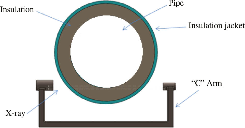
Components of real-time radiography.
Wolf (1995) recommended the use of real-time X-ray as an excellent alternative to stripping the insulation in search for pipe components, which demonstrated 99% field reliability of detecting circumferential welds with a weld crown of 1–2 mm.
5.6 Manual ultrasonic thickness measurement
This technique is considered one of the most expensive NDT methods for CUI inspection as it requires partial removal of the insulation material by making small holes that need to be sealed with cups or covers (see Figure 4), and then an ultrasonic thickness gauge can be used manually to measure the thickness under the hole. Results are usually accurate, and the technique is simple, fast and versatile. However, it has some limitations because it focuses only on small areas that are accessible and not always prone to CUI according to Twomey (1997); therefore, it is difficult to find enough inspection locations to do the measurement and have reliable data. There is a risk that more CUI may take place as a result of improper covering or sealing of the holes that were needed for the technique (Winnik, 2016).
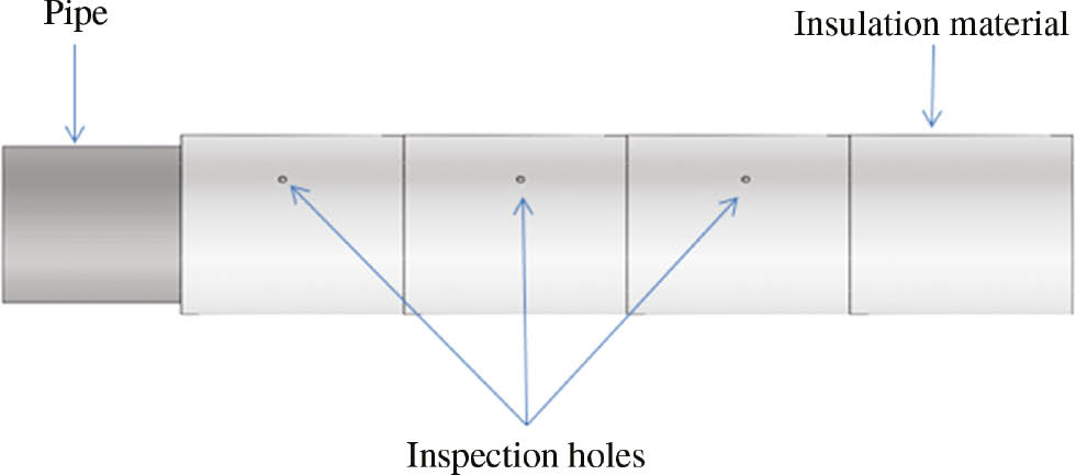
Ultrasonic thickness measurement by introducing holes on insulation materials.
5.7 Inspection of CUI using microwaves
In the previous Sections 5.1 to 5.6, it is clearly shown that there are some drawbacks and limitations to some of the available commercial CUI inspection techniques. These limitations encouraged and motivated researchers to look for more beneficial and reliable techniques that can be used to inspect miles of pipelines rather than short pipes. R. Jones, in her PhD thesis, Robin (2012), used microwaves for the detection of CUI. The author described the development of a new long-range inspection technique for CUI, which employs microwaves as an interrogating signal that travels along the pipe. The technique is capable of studying bends, pipe supports and different types of insulation materials. In her work, she described a variety of methods to guide the system; she eventually concluded that the pipe and the cladding around the insulation material as a coaxial waveguide is the best solution. When the signal travels through the system, trapped water under or inside the insulation will create an impedance discontinuity that causes signal reflections of the original signal. Such reflections can be detected to locate water accumulation. The system proves itself due to its capability of analyzing bends. Moreover, the range is relatively long compared to other available CUI inspection strategies.
6 Concluding remarks
In the light of all information given in this review article, it can be concluded that coatings represent the main protection against CUI. Therefore, great care has to be taken when selecting a coating system. The authors went further and suggested the use of GFRP as an extra protection measure to the ones suggested by Williams and Evans. This review paper sheds light on the importance of delivering more predictive models to the occurrence of CUI. It also shows the strength and limitations of the most critical inspection techniques that are being used to detect CUI in the industry, which will help the reader select a suitable technique. A comprehensive list of industrial standards dealing with CUI is provided. There is still an urgent need for more robust research and scientific endeavors and collaboration between industry and academia to fight CUI.
Despite many years of research in the area of CUI, there are still many questions and problems waiting for satisfactory answers and solutions. This unfortunate situation can be explained by the extreme complexity of this type of corrosion, as it involves different parameters including coating, insulation materials, metal, operation conditions and the corrosivity of the surrounding environment. Over the past years, endeavors to simplify the complexity of CUI received more attention. Both researchers and industry are keen to come up with new innovative technology to tackle CUI-related problems. However, their efforts are hampered by the fact that the prediction of the lifetime of insulation materials or coating by laboratory tests is not always precise. It is hoped that advancement in equipment and testing technology to analyze CUI will encourage scientists to do more research and help resolve the problems and failures incurred due to CUI, consequently reducing cost and fatality. It is worth mentioning that finding an economic comparison data for these techniques is highly significant; unfortunately, there are no economic data available in the open literature, which emphasizes the necessity for more work in this field.
About the authors

Elsadig O. Eltai holds a PhD from the University of Manchester (title of thesis: Epoxy coated steel pipeline under cathodic protection). Dr. Eltai has conducted successful research in different areas includes coatings, cathodic protection, welding, composites and pipeline. He is actively engaged with industry, trying to help them solve the challenges they are facing. Dr. Eltai has published more than 20 papers in high-impact factor journals. He is also a reviewer of many respected journals.

Farayi Musharavati is an associate professor in the Mechanical and Industrial Engineering Department, Qatar University. His research interests include intelligent manufacturing, materials engineering and design, renewable energy, sustainability, life cycle assessment, simulation modeling, applications of optimization techniques as well as engineering applications in biomedical research, desalination, biomedical applications and nano coating. He has published more than 50 technical papers.

El-sadig Mahdi has vast experience in research in materials science and engineering. He is active in different research areas such as corrosion, fatigue analysis of conventional materials, mechanical design, failure analysis, composite materials and finite element. He supervised Bachelor’s, Master’s and PhD theses. He has published over 200 technical papers. His current research is on materials for energy, corrosion-erosion and optimizing of advanced materials for the oil and gas industry.
References
API-570. Piping inspection code: in-service inspection, rating, repair, and alteration of piping systems, Washington, USA: American Petroleum Institute, 2016.Search in Google Scholar
API-581. Risk-Based Inspection Technologies, Washington, USA: American Petroleum Institute, 2008.Search in Google Scholar
API-583. Corrosion under insulation and fireproofing, 1st ed., Washington, USA: American Petroleum Institute, 2014.Search in Google Scholar
Arenas MP, Rocha TJ, Angani CS, Ribeiro AL, Ramos HG, Eckstein CB, Rebello JMA, Pereira GR. Novel austenitic steel ageing classification method using eddy current testing and a support vector machine. Measurement 2018; 127: 98–103.10.1016/j.measurement.2018.05.101Search in Google Scholar
ASTM-C795-08. Standard specification for thermal insulation for use in contact with austenitic stainless steel. San Antonio, TX, USA: ASTM Inter, 2018.Search in Google Scholar
ASTM-C692-13. Standard test method for evaluating the influence of thermal insulations on external stress corrosion cracking tendency of austenitic stainless steel. San Antonio, TX, USA: ASTM Inter, 2018.Search in Google Scholar
ASTM-C871-18. Standard test methods for chemical analysis of thermal insulation materials for leachable chloride, fluoride, silicate, and sodium ions. San Antonio, TX, USA: ASTM Inter, 2018.Search in Google Scholar
ASTM-G189. Guide for laboratory simulation of corrosion under insulation. San Antonio, TX, USA: ASTM Inter, 2013.Search in Google Scholar
Caines S, Khan F, Shirokoff J. Analysis of pitting corrosion on steel under insulation in marine environments. J Loss Preven Proc Indus 2013; 26: 1466–1483.10.1016/j.jlp.2013.09.010Search in Google Scholar
Caines S, Khan F, Shirokoff J, Qiu W. Experimental design to study corrosion under insulation in harsh marine environments. J Loss Preven Proc Indus 2015; 33: 39–51.10.1016/j.jlp.2014.10.014Search in Google Scholar
De Sousa F. Characterization of corrosive agents in polyurethane foams for thermal insulation of pipelines. Electro Acta 2007; 52: 7780–7785.10.1016/j.electacta.2006.12.074Search in Google Scholar
Delahunt JF. Corrosion under insulation and fire proofing – an overview. In: NACE Corrosion Conference. Houston, USA: NACE International, 2003.10.5006/C2003-03022Search in Google Scholar
Delaunois F, Tshimombo A, Stanciua V, Vitry V. Monitoring of chloride stress corrosion cracking of austenitic stainless steel: identification of the phases of the corrosion process and use of a modified accelerated test. Corr Sci 2016; 110: 273–283.10.1016/j.corsci.2016.04.038Search in Google Scholar
Dimitris IP, Theodora ET. Corrosion of weldments. In: El-Sherik AM, editor. Trends in oil and gas corrosion research and technologies. Cambridge, UK: Woodhead Publishing, 2017: 249–270.10.1016/B978-0-08-101105-8.00010-3Search in Google Scholar
DNV-RP-G101 Practice. Risk-based inspection of offshore topsides static mechanical equipment. Hovic, Norway: DET NORSKE VERITAS, 2010.Search in Google Scholar
El-Sayed A, Rassoul A, Rashad, E. On the cathodic protection of thermally insulated pipelines. Eng Failure Analy 2009; 16: 2047–2053.10.1016/j.engfailanal.2009.01.005Search in Google Scholar
Eltai EO. Epoxy coated mild steel under cathodic protection (CP). PhD thesis, The University of Manchester, 2009.Search in Google Scholar
Eltai EO, Scantlebury JD, Koroleva EV. Protective properties of intact un-pigmented epoxy coated mild steel under cathodic protection. Prog Org Coats 2012a; 73: 8–13.10.1016/j.porgcoat.2011.08.012Search in Google Scholar
Eltai EO, Scantlebury JD, Koroleva EV. The effects of different ionic migration on the performance of intact un-pigmented epoxy coated mild steel under cathodic protection. Prog Org Coats 2012b; 75: 79–85.10.1016/j.porgcoat.2012.03.011Search in Google Scholar
Eltai EO, Scantlebury JD, Koroleva EV. The effects of zinc ion on the performance of epoxy coated mild steel under cathodic protection. Prog Org Coats 2013; 76: 548–554.10.1016/j.porgcoat.2012.11.006Search in Google Scholar
Eltai EO, Al-Khalifa KN, Al-Ryashi A, Mahdi E, Hamouda AS. Investigating the corrosion under insulation (CUI) on steel pipe exposed to Arabian Gulf Sea water drops. Key Eng Mater 2016; 689: 148–153.10.4028/www.scientific.net/KEM.689.148Search in Google Scholar
Erturk M. Optimum insulation thicknesses of pipes with respect to different insulation materials, fuels and climate zones in Turkey. Energy 2016; 113: 991–1003.10.1016/j.energy.2016.07.115Search in Google Scholar
Geary W. Analysis of corrosion under insulation failure in a carbon steel refinery hydrocarbon line. Eng Failure Analy 2013; 1: 249–256.10.1016/j.csefa.2013.09.001Search in Google Scholar
Han QH, Wang X, Lu Y. Experimental investigation on the corrosion behavior of G20Mn5QT cast steel and butt weld with Q345D steel. Corr Sci 2018; 132: 194–203.10.1016/j.corsci.2017.12.031Search in Google Scholar
He X, Qin Y, Jiang W. Effect of welding parameters on microstructure and mechanical properties of laser-welded Al-Si coated 22MnB5 hot stamping steel. J Mater Process Techno 2019; 270: 285–292.10.1016/j.jmatprotec.2019.03.006Search in Google Scholar
Kayfeci M, Kecebas A, Gedik E. Determination of optimum insulation thickness of external walls with two different methods in cooling applications. Appl Therm Eng 2013; 50: 217–224.10.1016/j.applthermaleng.2012.06.031Search in Google Scholar
Lai S, Chen DY, Chen H, Fub YW. Pulsed eddy current testing of inner wall flows of pipe under insulation. Procedia Eng 2015; 130: 1658–1664.10.1016/j.proeng.2015.12.334Search in Google Scholar
Mahdi E, Eltai EO. Development of cost-effective composite repair system for oil/gas pipelines. Composite Structure 2018; 202: 802–806.10.1016/j.compstruct.2018.04.025Search in Google Scholar
Mayne JEO. The problem of painting rusty steel. J Appl Chem 1959; 9: 673–680.10.1002/jctb.5010091208Search in Google Scholar
Melchers RE. Probabilistic model for marine corrosion of steel for structural reliability assessment. J Structural Eng 2003; 129: 1484–1493.10.1061/(ASCE)0733-9445(2003)129:11(1484)Search in Google Scholar
Melchers RE. Pitting corrosion of mild steel in marine immersion environment – Part 1: maximum pit depth. Corrosion 2004; 60: 824–836.10.5006/1.3287863Search in Google Scholar
Mitchell VL. National board of boiler and pressure vessel inspectors. Preventing corrosion under insulation, engineering consultant. In: National Board Bulletin. La Grange, TX, USA, 1988: 6.Search in Google Scholar
Miyashita J. Performance of three types of coatings in a simulated corrosion under insulation condition. In: NACE Corrosion Conference. Houston, USA: NACE International, 2017.10.5006/C2017-09296Search in Google Scholar
NACE-6H189: A state-of-the-art-report on protective coatings for carbon steel and stainless steel surfaces under thermal insulation and cementitious fireproofing. Houston, TX, USA: NACE Inter, 1989.Search in Google Scholar
NACE-SP0198. The control of corrosion under thermal insulation and fireproofing materials – a systems approach. Houston, TX, USA: NACE Inter, 2017.Search in Google Scholar
NORSOK Standard M-501. Surface preparation and protective coating. Ed 6., Lysaker, Norway: NORSOK Standard, 2012.Search in Google Scholar
NORSOK Standard R-004. Piping and equipment insulation. Rev 2., Oslo, Norway: NORSOK Standard, June 1999.Search in Google Scholar
Poitanabuntoeng T, Ehsani H, Kinsella B, Brameld M. Comparison of insulation materials and their roles on corrosion under insulation. In: NACE Corrosion Conference and Expo. Houston, USA: NACE International, 2017.10.5006/C2017-09287Search in Google Scholar
Pollock WI, Barnhart JM. Corrosion of metals under thermal insulation. Philadelphia USA: ASTM Inter, 1985.10.1520/STP880-EBSearch in Google Scholar
Rakvin M, Markucic D, Hizman B. Evaluation of pipe wall thickness based on contrast measurement using computed radiography (CR). Procedia Eng 2014; 69: 1216–1224.10.1016/j.proeng.2014.03.112Search in Google Scholar
Ristimaki M, Saynajoki A, Heinonen J, Junnila S. Combining life cycle costing and life cycle assessment for an analysis of a new residential district energy system. Des Ener 2013; 63: 168–179.10.1016/j.energy.2013.10.030Search in Google Scholar
Robin EJ. Use of microwaves for the detection of corrosion under insulation. PhD thesis, Imperial College London, 2012.Search in Google Scholar
Sedriks AJ. Stress-corrosion cracking of stainless steels, stress corrosion cracking, materials performance and evaluation. In: Jones RH, editor. ASM Inter, Materials Park. Ohio, USA: ASM Inter, 1992: 91–130.Search in Google Scholar
Shim HS, Choi MS, Lee DH, Hur DH. A prediction method for the general corrosion behavior of Alloy 690 steam generator tube using eddy current testing. Nucl Eng Des 2016; 297: 26–31.10.1016/j.nucengdes.2015.11.015Search in Google Scholar
Shong D. Understanding Insulation Chemistry Proven to Inhibit Corrosion Under Insulation (CUI). In: NACE Corrosion Conference and Expo. Houston, USA: NACE International, 2017.10.5006/C2017-08876Search in Google Scholar
Soeren Z, Rasmussen C. Cyclic CUI testing of insulation materials. In: NACE Corrosion Conference and Expo. Houston, USA: NACE International, 2017.Search in Google Scholar
Twomey M. Inspection techniques for detecting corrosion under insulation. Mater Eval 1997; 55: 129–132.Search in Google Scholar
Uygunoglu T, Kecebas A. LCC analysis for energy-saving in residential buildings with different types of construction masonry blocks. Ener Buil 2011; 43: 2077–2085.10.1016/j.enbuild.2011.04.011Search in Google Scholar
Wilds N. Corrosion under insulation. In: Energy Trends in Oil and Gas Corrosion Research and Technologies. Duxford, UK: Woodhead Publishing, 2017: 409–429.10.1016/B978-0-08-101105-8.00017-6Search in Google Scholar
Williams J, Evans O. The influence of insulation materials on corrosion under insulation. In: NACE Corrosion Conference. Houston, USA: NACE International, 2010.Search in Google Scholar
Winnik S. Piping system CUI: old problem; different approaches. In: The European Federation of Corrosion Conference Corrosion in the Refinery Industry. Budapest, Hungary; Cambridge, UK, 2003.Search in Google Scholar
Winnik S. Corrosion-under-insulation (CUI) guidelines, 2nd ed., Cambridge, UK: Woodhead Publishing, 2016.Search in Google Scholar
Wolf HA. Positive materials identification of existing equipment. In: Sims JR, editor. Second Inter Symp on Mech Integr of Proc Piping. St. Louis, MO, USA: MTI Publication, 1995: 48–51.Search in Google Scholar
Xiaokang Y, David AH, Guoming C, Wei L. Detecting surface features on conducting specimens through an insulation layer using a capacitive imaging technique. NDT&E Inter 2012; 52: 157–166.10.1016/j.ndteint.2012.08.004Search in Google Scholar
Yin X, Hutchins DA, Chen G, Li W. Investigations into the measurement sensitivity distribution of coplanar capacitive imaging probes. NDT&E Inter 2013; 58: 1–9.10.1016/j.ndteint.2013.04.001Search in Google Scholar
Yin K, Yang Y, Frank C. Permeability of coal tar enamel coating to cathodic protection current on pipelines. Constr Buil Mate 2018; 192: 20–27.10.1016/j.conbuildmat.2018.10.123Search in Google Scholar
©2020 Elsadig O. Eltai et al., published by De Gruyter, Berlin/Boston
This work is licensed under the Creative Commons Attribution 4.0 International License.
Articles in the same Issue
- Frontmatter
- In this issue
- Reviews
- An updated review on TiNi alloy for biomedical applications
- Severity of corrosion under insulation (CUI) to structures and strategies to detect it
- Original articles
- Corrosion protection performance of nano-TiO2-containing phosphate coatings obtained by anodic electrochemical treatment
- Influence of heat treatment on the corrosion properties of CuAlMn shape memory alloys
- Annual reviewer acknowledgement
- Reviewer acknowledgement Corrosion Reviews volume 37 (2019)