Corrosion protection performance of nano-TiO2-containing phosphate coatings obtained by anodic electrochemical treatment
-


Abstract
The efficacy of nano-TiO2-containing zinc phosphate coatings on low-carbon steel is investigated. Zinc phosphate coatings are electrodeposited on low-carbon steel (AISI 1015) keeping current density, deposition time and wt % nano-TiO2 at their respective levels. Corrosion protection performance of these coatings was assessed using potentiodynamic polarization curves and electrochemical impedance spectroscopy (EIS) in 3.5% NaCl electrolyte. The morphology, the composition and the growth process of the zinc phosphate coating is investigated using scanning electron microscopy (SEM), energy-dispersive X-ray spectroscopy, X-ray diffraction (XRD) and electrochemical measurements. The XRD study reveals that the obtained phosphate layer contains traces of hopeite and phosphophylite. The formed zinc phosphate coating offers high corrosion protection in 3.5% NaCl solution, which is well supported by EIS studies. The presence of nano-TiO2 in the phosphate bath anticipated to offer a better surface coverage and reduction in porosity and forms more homogeneous coating, which is in agreement with the SEM studies. The optimization of the electrodeposition phosphating process for achieving better responses in terms of corrosion rate and coating resistance is addressed in this paper.
1 Introduction
Metals and their alloys are favored to undergo corrosion events within its environment. Corrosion is the common deterioration of metal experienced when it reacts with its environment (Fontana, 2005). It is a well-established fact that electrochemical inhomogeneity in metals and its environment is the prima facie for corrosion reaction to happen. The more effective way to prevent such corrosion events is to coat the substrate material. Precisely organic coatings would provide lifelong protection, but surface defects during service time limits their use (Deshpande et al., 2014). In the current scenario, development of self-heal coating (shape memory materials and conductive polymers) is turning out to be trustworthy for the protection of metals against corrosion (DeBerry, 1985; Wessling, 1994; Ahmad & MacDiarmid, 1996).
Phosphating is a common and efficient industrial surface treatment for corrosion protection of metallic surfaces (Sankara Narayanan, 2005). It is widely used in many industries, either for corrosion protection, for surface pretreatment or for decorative purposes (Lorin, 1974; Gentil, 1987). The main types of phosphate baths are iron, manganese and zinc based (Diaz et al., 2015). Zinc phosphate coating has a unique crystalline structure and is highly adherent to underlying metal. The formation of insoluble phosphate salts, particularly zinc phosphate, takes place due to its conversion characteristics. There is a wealth of literature available on the applicability of zinc phosphate coatings on steels (Banczek et al., 2006), galvanized steel (Bustamante et al., 2003; Rout et al., 2006), aluminum (Whitten & Lin, 2000; Akhtar et al., 2004), magnesium (Kouisni et al., 2004; Lian et al., 2006; Niu et al., 2006) and zinc (Jegannathan et al., 2005). Zinc phosphate has its large-scale implications in rust proofing, lubricant-based layer and paint coatings-based industries (Banczek et al., 2008).
These phosphate coatings are anticipated to offer long-lasting protection. However, dissolution of zinc during phosphating is a serious problem as it adversely affects the corrosion protection performance of the subsequent paint system. Attempts have been made to reduce zinc dissolution and to enhance the performance of phosphate primer. It is expected that the addition of nano metal dioxide particles may improve the performance of the primer (Shibli & Chacko, 2011). Studies on phosphate coatings reported that conventional zinc phosphating process precludes dissolution of the metal base in the phosphoric acid present in the bath and subsequent hydrogen evaluation, and rise of interfacial pH takes place at the metal-liquid interface (Lorin, 1974; Gentil, 1987; Sankara Narayanan, 2005; Banczek et al., 2006; Diaz et al., 2015). In recent years, attempts have been made to improve the conventional phosphating method by electrochemical means, with electricity serving as an accelerator. This would make this process more eco-friendly as compared to chemical phosphating (Sinha & Feser, 2002).
As mentioned above, electric current is one of the phosphating accelerator agents. Apart from electric current, chemical compounds might be the salts of metal that is more noble than the metal to be phosphated, or oxidant compounds also serve the function of an accelerator. In comparison with current density, chemical accelerators are relatively less expensive. The accelerator in phosphating has the function of depolarizing the surface reactions occurring due to high electronic density at microcathodic sites.
The electrochemical phosphating method yields better corrosion resistance than chemical phosphating at room temperature (Jegannathan et al., 2006a,b). The insulating nature of these coating reflects in the protection against corrosion (Weng et al., 1996). Many new techniques of deposition are now being investigated with the development of modern industry, including various process variables: current density, pH of the phosphating bath, bath temperature, deposition time and degreasing time. Optimization of these process parameters in the zinc phosphating process by chemical means was reported by Chen et al. (2006).
The notable work by Diaz et al. (2015) fetches particular attention toward the optimization of activation time during the phosphate coating process on high-strength steel. Adhesion of electrodeposited phosphate-coated steel sheet and its process optimization were investigated by Nitu Rani et al. (2012). Generally, the cold forming process facilitated by phosphate coatings offers an excellent insulation property. In order to have sufficient electrical contact with the underlying metal, coatings should contain 80–90 wt % of zinc. So, these coatings will protect subsequent metal either by sacrificial mechanisms or by cathodic protection. Similarly, an impervious coating may be an option, provided that these coatings do not develop any physical defects during their service.
The conventional phosphating methods and their feasibility were reported in several literatures. It is worth noting that process parameters in the pretreatment procedure (degreasing temperature, degreasing time and concentration of degreasing agent) and operating conditions (bath temperature) would influence the coating morphology, thickness and crystalline structure of the coating and subsequently affect the corrosion protection performance of the phosphate layer (Bhar et al., 1988; Ogle et al., 2004; Zhang et al., 2008a,b). It has also been observed that the incorporation of metal salts in the phosphating bath can manipulate the microstructure of the zinc phosphate coating, which, in turn, made the coating denser and finer (Sun et al., 2002). It has been reported that some conventional surface treatments depend on chromate and chromate-phosphate coatings, which can provide a superior level of under-film corrosion protection and excellent adhesion (Brooman, 2002). However, on the second verdict, chromate is more susceptible to toxic nature, so, as a matter of fact, efforts are underway to find an alternative for these toxic methods (Twite & Bierwagen, 1988). Hence, zinc phosphate coating seems promising.
To sum up, paint coating/primer is indeed a requirement to protect a metal from subsequent corrosion attack. So, zinc-rich coatings overcome the above limitations and can be a suitable candidate due to their non-toxic nature, excellent stability and environment-friendly property. To the best of our knowledge, the optimization of the electrodeposition process for achieving maximum coating resistance and minimum corrosion rate simultaneously is yet to be strongly investigated. Few studies in the literature reported on optimization of chemically deposited phosphate coatings (Chen et al., 2006). However, Nitu Rani et al. (2012) optimized the electrodeposited coating process and assessed it for morphological changes and thickness. The critique presented above identifies the gap between the study on the corrosion behavior of electrodeposited phosphate-coated metal, the change in morphology of electrodeposited coating at various process parameters and the optimal setting of input controlled process variables during electrodeposition. This inspired us to examine the growth behavior of electrodeposited phosphate coating with varying input controlled process variables (i.e. current density, deposition time and wt % nano-TiO2). This paper proposes a novel approach to assess the corrosion protection performance of electrodeposited nano-TiO2-incorporated zinc phosphate coating using the robust Taguchi technique, thus reducing experimental efforts and cost.
In the present campaign, therefore, to enhance the corrosion protection performance of low-carbon steel (LCS) and to protect it from local oxidation, phosphating bath containing ZnO, H3PO4 and nano-TiO2 is applied to form zinc phosphate coatings on LCS by electrochemical means. A specially designed Taguchi L9 orthogonal array is used to conduct the experiments, keeping the process variables: current density, deposition time and wt % of nano-TiO2 at their different levels. The growth process and phosphating mechanism are explored in detail by means of scanning electron microscopy (SEM), energy-dispersive X-ray spectroscopy (EDX), X-ray diffraction (XRD) and time-potential curve. The corrosion protection performance of the coating is estimated by potentiodynamic polarization curves. This paper emphasizes on the viability of electrodeposited zinc-rich phosphate coating as an environmental-friendly alternative and, thus, ensures the high fidelity in surface treatment industries.
2 Materials and methods
Electrodeposition of phosphate coatings was carried out on LCS (AISI 1015). Rectangular samples (80 mm×20 mm×0.3 mm) were mechanically grinded by SiC emery paper with grit size sequence of 600, 800, 1500 and 2500 to have a mirror finish surface. After polishing, all the samples were ultrasonically cleaned in acetone followed by warm air drying. Subsequently, the samples were dipped in titanium phosphate salt with pH 8–9.5 for 120 s at room temperature for surface activation. The area exposed for electrodeposition was 50 mm×20 mm×0.3 mm. The prepared samples were immersed in water-based zinc phosphate bath containing zinc oxide (Sigma-Aldrich, Bangalore, India), which is the source of zinc, and orthophosphoric acid (Ankit Enterprises, Vapi, India) with permissible amount of sodium hydroxide. The composition of AISI 1015 steel is given in Table 1, and the chemical composition of the phosphating bath is shown in Table 2. The readers are advised to go through the literature (Sinha & Feser, 2002; Jegannathan et al., 2006a,b) for a detailed information about the phosphating process. The weight of the phosphate layer deposited was measured after solubilization of the phosphate layer in 0.5 g/l chromium trioxide (Sigma-Aldrich, Bangalore, India) for 20 min at 60±5°C, followed by weighing and measuring w2. The phosphate layer weight estimated is given by Equation 1:
The composition of AISI 1015 LCS.
| Element | C | Si | Mn | P | S | Cr | Ni | Mo | Fe |
|---|---|---|---|---|---|---|---|---|---|
| Composition (wt %) | 0.15 | 0.025 | 0.50 | 0.03 | 0.03 | 0.025 | 0.028 | 0.002 | Bal. |
Chemical composition of phosphate bath.
| Chemicals | Molecular weight (g/mol) | Quantity |
|---|---|---|
| Zinc oxide (ZnO) | 81.408 | 2.04 g/l |
| Orthophosphoric acid (H3PO4) | 98 | 16 ml/l |
| Sodium hydroxide (NaOH) | 39.997 | 6.67 g/l |
| Nano-TiO2 | 79.86 | 0.5 g, 1.5 g, 2 g |
where w1 is the weight of the phosphated substrate, w2 is the weight after phosphate layer solubilization and A is the exposed surface area in the phosphating solution.
In the zinc phosphate electrodeposition process, current density, deposition time and wt % of nano-TiO2 (Sigma-Aldrich, Bangalore, India) were taken as input controlled process variables, and they were set to their various levels (Table 3). These predetermined levels of input controlled process variables were customized by trial and error experiments and taking into account previous reports. The Taguchi L9 orthogonal array was created in order to run the experiments (Table 4). For the sake of repeatability and precision, each experiment was conducted thrice. Analysis of variance (ANOVA) and regression analysis were carried out using the MINITAB 15 software (MINITAB, LLC, PA, USA).
Selection of process variables and their different levels.
| Process variables | Code | Levels |
||
|---|---|---|---|---|
| 1 | 2 | 3 | ||
| Current density (mA/cm2) | A | 2 | 4 | 6 |
| Deposition time (min) | B | 20 | 40 | 60 |
| wt % nano-TiO2 (particle size ~21 nm) | C | 0.5 | 1.5 | 2 |
Taguchi L9 orthogonal array.
| Experiment | A | B | C |
|---|---|---|---|
| 1 | 1 | 1 | 1 |
| 2 | 1 | 2 | 2 |
| 3 | 1 | 3 | 3 |
| 4 | 2 | 1 | 3 |
| 5 | 2 | 2 | 1 |
| 6 | 2 | 3 | 2 |
| 7 | 3 | 1 | 2 |
| 8 | 3 | 2 | 3 |
| 9 | 3 | 3 | 1 |
The surface morphology and compositions of the coating formed were studied by SEM (ZIESS Supra 55, WARWICK, UK) and EDX (TN-5402, WARWICK, UK). The elemental phases in the electrodeposited phosphate coatings were identified by XRD studies (Rigaku SmartLab, TX, USA) using an automated multipurpose X-ray diffractometer with Cu/Kα radiation. However, readers are advised to go through our previous work cited (Bagal et al., 2018) for the optical absorbance characteristics of the nano-TiO2 powder synthesized by the sol-gel method by supplier and characterized by a ultraviolet-visible (UV-vis) spectrometer.
The growth of the phosphate coating was studied using time vs. potential behavior. The open circuit potential (OCP) was monitored continuously vs. saturated calomel electrode (SCE) during the phosphating process. The electrochemical polarization studies of the electrodeposited nano-TiO2 phosphate-coated samples and chemically deposited nano-TiO2 phosphate-coated samples in 3.5% NaCl electrolyte at room temperature were carried out. A typical three-electrode system composed of SCE as reference electrode, platinum electrode as counter electrode and coated sample as working electrode was deployed to assess the electrochemical polarization measurements. The Gamry framework electrochemical analysis instrument with corresponding Gamry software was used for analysis. This electrochemical impedance spectroscopy (EIS) and potentiodynamic polarization study was carried out according to the ASTM G106 and ASTM G3–74 course of action, respectively.
3 Results and discussion
3.1 Electrodeposition and characterization of the phosphate layer
The electrodeposition process of phosphate coatings obtained by an anodic electrochemical treatment as a function of process variables’ current density and temperature was well described by Jegannathan et al. (2005). Therefore, in this work, only the mechanism of coating formation and relevant details are outlined for the sake of brevity. In the electrodeposition of phosphate coatings, LCS was used as the anode, and graphite rod as the cathode. Electrodeposition of the phosphate coating takes place in two stages: nucleation and growth. During this process, the potential of LCS was controlled continuously as a function of time by following the OCP. It was found that any normal phosphating process takes place in two steps: metal dissolution followed by phosphate deposition.
It was observed that impressed current is the key factor for the high rate of metal dissolution. As the first of its kind, potential is shifted toward the anodic region and attains a maximum value. Hydrogen evaluation can be seen at the graphite rods (cathodic sites). The increase in deposition time leads to a shift in the potential of substrate toward the cathodic region. Several literature reports (Banczek et al., 2006; Jegannathan et al., 2006a,b; Yantapure et al., 2015) revealed that the observed anodic shift at the start of deposition is due to the depletion of H+ ions in the electrode/electrolyte interface caused by repulsive forces of ferrous ions and the positive charge on the substrate. In this electrodeposition process, initially, hydrogen evaluation was shifted and a rise in interfacial pH is expected near the graphite rod (cathodic region) until it attains maximum value (Figure 1). At this point, rapid growth of phosphate coatings may be expected. Meanwhile, more dissolution of LCS was observed, probably due to the impressed anodic current, thus by generating greater amounts of ferrous ions. However, maximum potential suggests the conversion of primary soluble phosphate into tertiary insoluble phosphate, which makes phosphate coatings insoluble in nature.
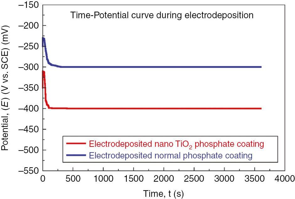
Variation in potential with respect to time during electrodeposition of nano-TiO2 containing phosphate coating and normal phosphate on low carbon steel.
The potential significantly declines with time after shifting toward the cathodic sites until it attains stability (150 s). At this stage, the phosphate coatings formed were denser. This can be explained by displacement of protons away from the LCS/phosphating solution interfaces, and this reflects a slight increase in interfacial pH and reveals the anodic shift of the potential. This rise in interfacial pH has to assist the deposition of phosphate coating on LCS anode. This agrees well with the study reported by Jegannathan et al. (2005). Conversion of primary soluble phosphate into tertiary insoluble phosphate suggests the attainment of maximum potential.
The average weight of nano-TiO2-incorporated phosphate layers obtained by electrodeposition and chemical deposition (Bagal et al., 2018) at various times of immersion is shown in Figure 2. The average weight of phosphate coatings obtained by electrochemical means is higher than that of its counterpart, chemically deposited coatings. This could be justified by the presence of the nano-TiO2 trace as an additive in the phosphate layer. It is evident from Figure 2 that, for a given time, iron dissolution is of high order (approximately 40–55 g/m2 per 10 min). However, phosphate coatings showed dissolution of low order (6–9 g/m2) for the same time. It is anticipated that the immersion time is required in order to characterize the coating stabilization. The relationship between coating weight and coating thickness is given elsewhere in the literature (Weng et al., 1996). Most of the phosphate coatings exhibit relation of 1-μm thickness to 1.5–2 g/m2.
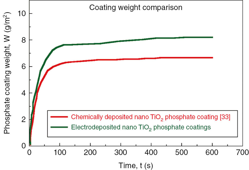
Variation in phosphate coating weight at various electrodeposition time.
The reactions occurring at the metallic surface and the mechanism of formation of the phosphate coating are illustrated in Figure 3 and below:
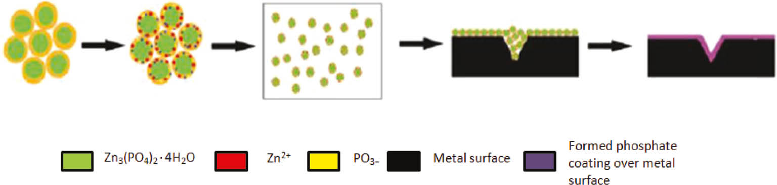
Mechanism of phosphate coating formation on metal substrate.
The first reaction reveals a metal attack by an acid in the phosphating solution, followed by the other two, which lead to the formation of phosphate crystals and deposition on metallic surface. The Zn3(PO4)2.4H2O (hopeite) is the main constituent in phosphate coating. The reaction 3 above advances continuously until the nucleation and growth of the coating, thus ensuring the maximum coverage of all micro anodic sites.
The XRD studies reveal an identification of various phases that would occur in the phosphate layer. The phases present in the phosphate layers were mainly identified as a trace of Zn3(PO4)2.4H2O (hopeite) and Zn2FE(PO4)2.4H2O (phosphophylite) (Figure 4). The XRD analysis identifies the peaks of hopeite and phosphophylite in the phosphate layer formed on LCS. The peaks of Fe are anticipated to contribute porosity in the phosphate coatings.
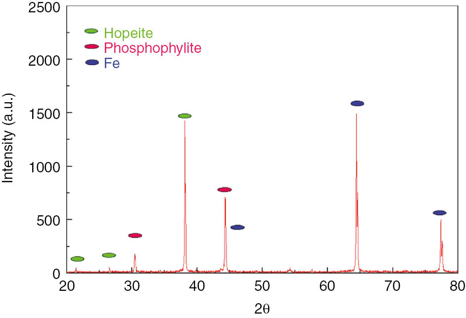
X-ray diffraction (XRD) patterns of the zinc phosphate layer deposited on low carbon steel.
3.2 Morphology characterization of the phosphate layer
The surface morphology of the electrodeposited zinc phosphate coatings obtained without and with nano-TiO2 at an optimized condition (current density 4 mA/cm2, deposition time 60 min and 0.5 wt % nano-TiO2) was studied to observe the growth of the phosphate coating on LCS. In both cases, formation of a well-crystallized coating was observed. It is worth recalling Machu’s hypothesis (Machu, 1943) of precipitation of metal phosphates; these crystals can be initiated on cathodic sites. The color of the coatings observed was dark gray for the normal electrodeposited phosphate and gray for nano-TiO2-containing electrodeposited phosphate and has needle-like structures. The significant difference was traced in the surface morphology of these two coatings. Compared to the normal electrodeposited phosphate coating surface, the surface of nano-TiO2-containing coatings was more homogeneous.
It may be expected that the number of pores was less in the case of the coatings containing nano-TiO2 due to the sealing effect by nano-TiO2 particles. It is possible that nano-TiO2 particles play a crucial role in preventing the subsequent coatings from their inhabitant behavior. The incorporation of nano-TiO2 into the phosphating bath caused structural refinement of the crystal and also helped to achieve maximum surface coverage (Figure 5). The SEM micrographs confirm that the results obtained by the EIS studies are in line with the previous studies reported by Zhang et al. (2008b).
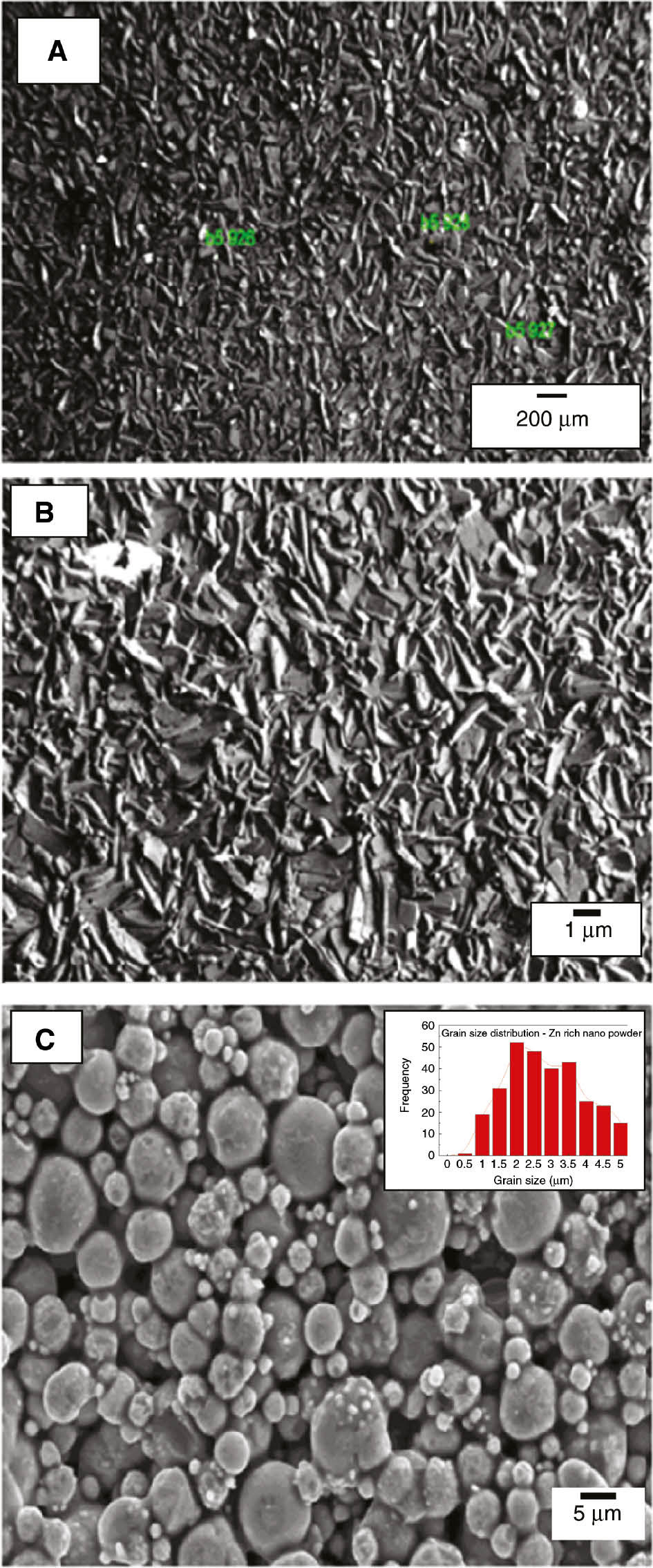
Representative images of scanning electron microscopy study for electrodeposited zinc phosphate coatings indicating (a) normal phosphate coatings, (b) incorporated with nano-TiO2 (optimized condition: current density 4 mA/cm2, deposition time 60 min and 0.5 wt % nano-TiO2) and (c) Zn-rich powder.
The EDX signals of the electrodeposited normal zinc phosphate coatings and those obtained at the optimized condition are depicted in the chemical composition of the phosphate coatings (Figure 6). The presence of nano-TiO2 was confirmed by above EDX studies. Further EDX analysis reveals a significant increase in Zn/P ratio from 3.58 to 3.80 for the coatings obtained using normal phosphating bath and nano-TiO2-containing phosphating bath, which, in turn, led to the increase in the content of Zn3(PO4)2·4H2O.
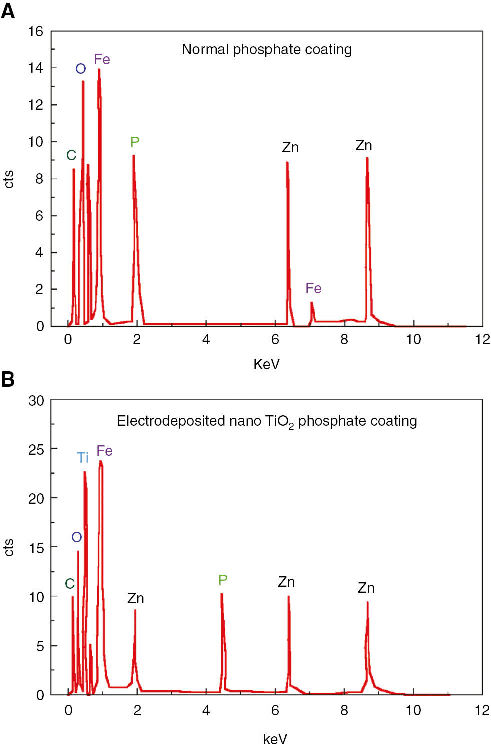
Energy dispersive spectroscopy (EDS) analysis of electrodeposited zinc phosphate coatings (a) normal phosphate coatings (b) phosphate coatings containing 0.5 g/L nano TiO2 (at optimized condition).
3.3 Electrochemical characterization
The polarization curves corresponding to bare, chemically deposited nano-TiO2 phosphate-coated and electrodeposited nano-TiO2 phosphate-coated LCS are shown in Figure 7. Polarization methods are faster experimental techniques for the determination of corrosion rates than the conventional weight loss method. The coated samples were immersed in 3.5% NaCl electrolyte to obtain the Tafel plots. Here, in this work, we obtained a reasonably steady Tafel plots (both anodic and cathodic) after the stabilization of OCP. This technique permits measurement of accurate and precise corrosion rates (even corrosion rate <0.2 milli inches per year (mpy)). At the end, the framework calculates the corrosion rates by following formula:
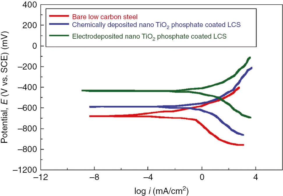
Representative polarization curves for bare low carbon steel, chemically deposited nano TiO2 containing phosphate coating and nano TiO2 containing electrodeposited phosphate coatings on low carbon steel in 3.5% NaCl electrolyte.
where
It is evident from the polarization curves that anodic polarization reveals the corrosion protection offered by the coating, while cathodic polarization suggests the evaluation of hydrogen. The results showed that electrodeposited nano-TiO2 phosphate-coated samples exhibit more corrosion resistance. The experimental findings reveal that the cathodic shift in Ecorr and the increased magnitude of Icorr, essentially with increase in current density, make the coating more porous and discontinuous. This was observed during the experiments 8 and 9 (Table 4), as increased current density under the influence of anodic current caused a dissolution of coatings. However, cathodic reactions in polarization curves tend to show a diffusion-controlled mechanism. In comparison with bare and chemically deposited coatings, electrodeposited coatings show a decrease in corrosion current density (−8.445 mA/cm2), and corrosion potential is shifted toward the positive side. The addition of nano-TiO2 in the phosphate bath is expected to enhance the corrosion protection performance of coatings by forming the more compact phosphate layer. The observed results are in agreement with the OCP and SEM measurements. Figure 7 shows the Tafel polarization curves for bare, chemically deposited nano-TiO2 phosphate-coated and electrodeposited nano-TiO2 phosphate-coated LCS. The corrosion rate of electrodeposited phosphate-coated samples were found to be in the range of 0.8 to 2 mpy (Table 5), which was approximately eight times less than that of bare LCS in 3.5% NaCl solution. The corrosion inhibition efficiency for each sample was evaluated using Equation 6:
Polarization study observations of the phosphate-coated sample.
| Experiment | I corr (nA/cm2) | E corr (mV) | Corrosion rate (mpy) | Efficiency (%) |
|---|---|---|---|---|
| 1 | 484 | −505 | 1.26 | 89.6 |
| 2 | 182.2 | −563.4 | 0.722 | 93.89 |
| 3 | 256.8 | −711 | 1.27 | 89.3 |
| 4 | 458 | −724.8 | 1.40 | 88.33 |
| 5 | 415 | −623.5 | 1.86 | 84.5 |
| 6 | 105.8 | −634.8 | 1.38 | 94.87 |
| 7 | 493 | −663 | 1.44 | 88 |
| 8 | 579.2 | −720.5 | 1.07 | 91.08 |
| 9 | 524.4 | −681.8 | 2.05 | 82.91 |
where ηcorr is the corrosion efficiency,
Corrosion rate is one of the output responses in this work. Corrosion rate obtained from the above potentiodynamic polarization study using the Tafel analysis was investigated for regression analysis through the MINITAB 15 software. Measured and predicted values were compared (Figure 8). The regression model proposed is given below:
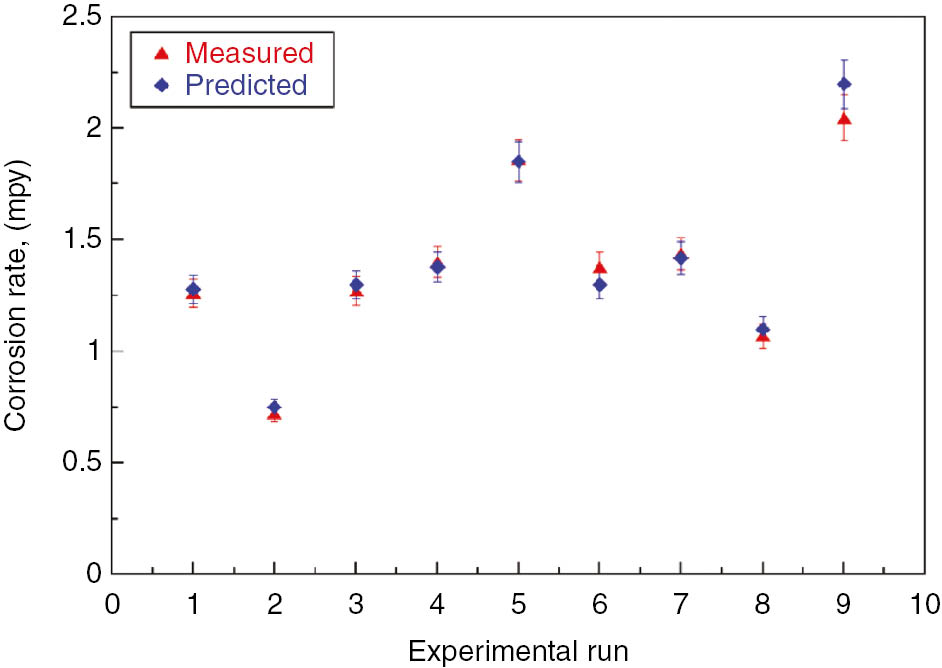
Variation in experimentally measured and predicted values of corrosion rate.
Corrosion rate=0.524+0.132 (current density)+0.0112 (deposition time) – 0.882 (wt % TiO2)
Generally, it has been observed that phosphate coatings are porous in nature, which is a detrimental factor for corrosion rate. Hence, the presence of nano-TiO2 particles helps in the reduction of porosity. In this work, coatings were electrodeposited by an anodic electrochemical treatment using current density and deposition time as major process parameters. It was observed from the above results that too high deposition time along with high current density results in unstable coatings, and such coatings are susceptible to damage. ANOVA was performed, which helps in assessing the contribution of each process variable and the chance of process improvement.
The EIS results obtained in the 3.5% NaCl solution are demonstrated in Figure 9 (Nyquist plots) and Figure 10 (Bode plots) and compared with the previous work of Jegannathan et al. (2006a,b). For bare LCS, only a time constant is shown. The Nyquist plot shown below reveals two capacitive arcs, suggesting two time constants: semicircle in the high-frequency region followed by diffusion tail in low-frequency region. The existence of the diffusion tail in the low-frequency region suggests that the phosphate coating formation is a diffusion-controlled process. However, we found that the obtained Nyquist curves are in line with the previous established work of Jegannathan et al. (2006a,b). Coatings with a current density of 4 mA/cm2 showed high impedance values. The Bode plot at high frequency shows the high impedance value and interaction between the time constants. Figure 10 manifests the higher impedance values for the phosphate coatings on LCS obtained by the electrodeposition process and are compared with those obtained by Jegannathan et al. (2006a,b). This shows the pores resistance to electrolyte penetration. This Bode plots support the previous results indicating the superior corrosion resistance of the electrodeposited phosphate layer. The higher impedance values of nano-TiO2 electrodeposited phosphate coatings reveals higher coating resistance. However, we observed that the Bode plots tend to show a single inflation point in the plot of Zmod vs. frequency.
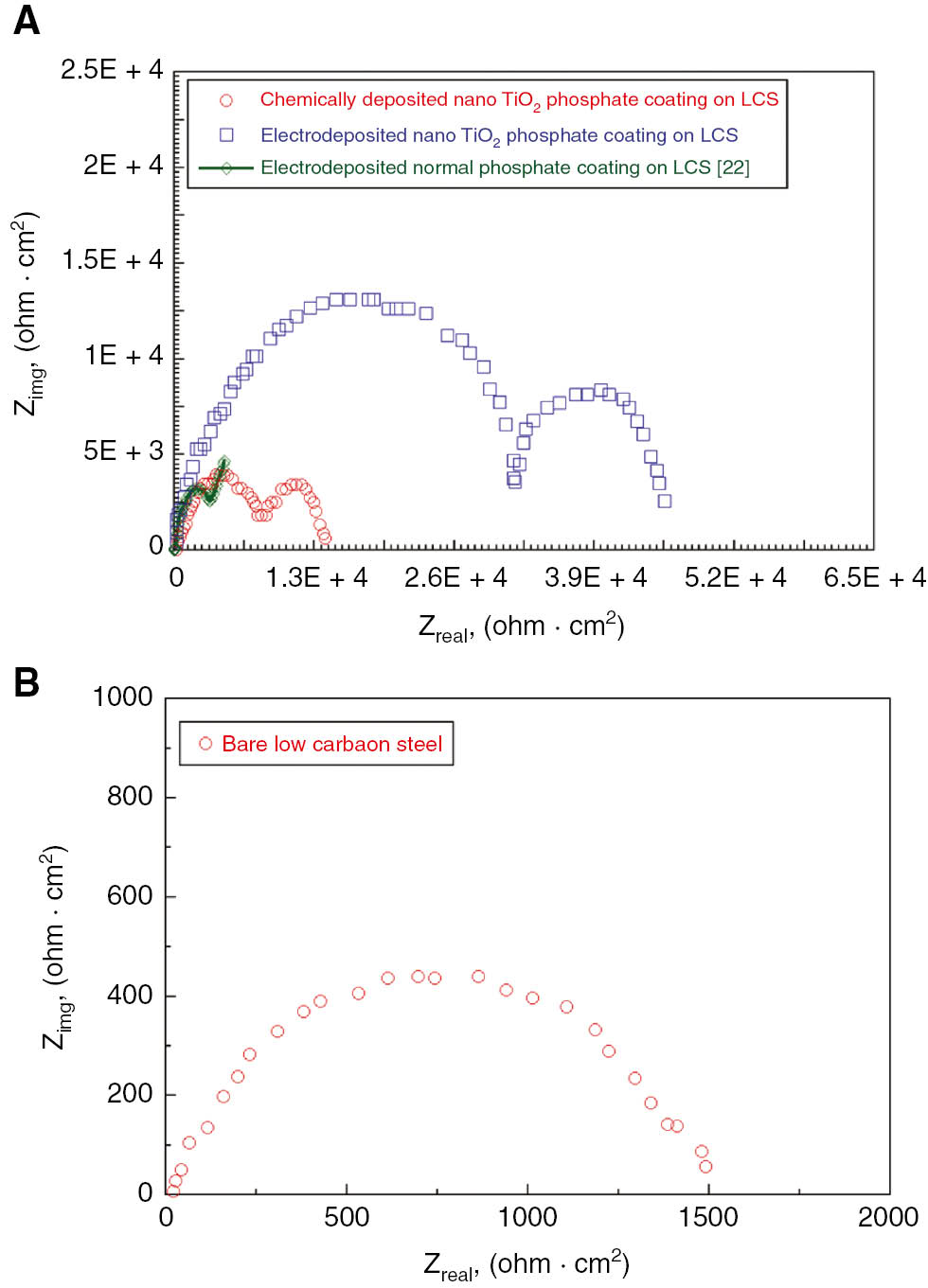
Nyquist plots for (a) chemically deposited and electrodeposited nano TiO2 phosphate coating on low carbon steel and (b) bare low carbon steel in 3.5% NaCl solution.
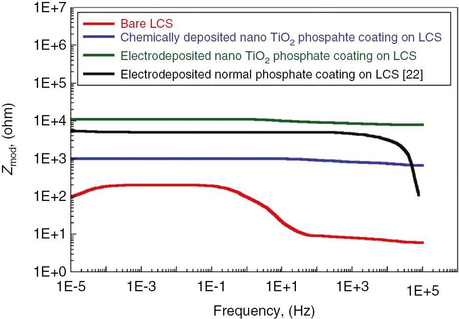
Bode plots for bare low carbon steel, chemically deposited and electrodeposited nano TiO2 phosphate coated low carbon steel and in 3.5% NaCl solution.
From the results, it was observed that the value of Zmod decreases as the current density increased from 4 to 6 mA/cm2 (Table 6). However, coating capacitance showed an increased trend as a function of deposition time. This eventually confirms that the increased current density leads to an increase in porosity in the coatings and that the coating may get damaged easily. Therefore, in the current work, being more porous, the electrodeposited nano-TiO2 phosphate coating at a current density of 6 mA/cm2 showed less corrosion resistance. Rise in interfacial pH can be an essential condition for deposition of phosphate coating on the steel substrate. The magnitude of coating weight is substantially less at high current density.
EIS results for zinc phosphate-coated sample.
| Experiment | Coating capacitance (F) | Z mod (kΩ) |
|---|---|---|
| 1 | 0.054 | 0.980 |
| 2 | 0.042 | 2.953 |
| 3 | 0.020 | 3.485 |
| 4 | 0.037 | 1.031 |
| 5 | 0.028 | 1.453 |
| 6 | 0.015 | 10.21 |
| 7 | 0.25 | 0.909 |
| 8 | 0.48 | 1 |
| 9 | 0.37 | 1.519 |
Further the coating resistance increased as the deposition time was increased from 20 to 60 min at the same current density. Increased deposition time yields increased coating thickness (Sankara Narayanan, 2005; Yantapure et al., 2015). The Gamry framework instrument allows electrochemical behavior to be modeled using constant phase element (CPE) instead of pure capacitance. So, to study the corrosion behavior of obtained electrodeposited nano-TiO2 phosphate coatings on LCS, an equivalent electrical circuit is drawn. Figure 11 shows equivalent circuit to demonstrate the impedance behavior of all samples. Here, in this study, we assumed that proposed model/circuit accounts for coating-metal/electrolyte interface. Our proposed model closely resembles the one used by (Meszaros et al., 1989; Weng et al., 1996). R1 is the ohmic resistance of the solution between the working and reference electrodes. This aforementioned resistance is strongly influenced by the solution concentration and sample area. R2 is the electrolytic resistance through the pores and parallel to coating capacitance (Cc). The charge transfer resistance R3 is parallel to double layer capacitance (Cdl) at the coating/metal interface (CPE). The purpose of including resistance and capacitance in the model is to encounter the changes taking place at the metal/electrolyte interface. The electrochemical behavior of the phosphate layers on zinc-coated LCS obtained using EIS corresponds with the previous literature (Weng et al., 1996; Wolynec, 2003). The double layer capacitance (Cdl) was calculated by obtaining the best curve fit to EIS curves using the Kaleida 4.0 software. The R2 value 0.9674 indicates goodness of fit and less variability of fitted data around the mean. As the first kind, the double layer capacitance (Cdl) showed an increasing trend with increase in current density from 4 to 6 mA/cm2.
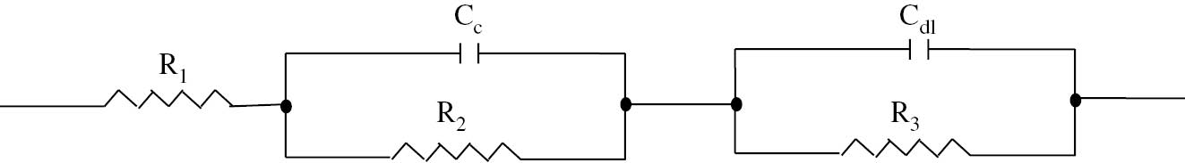
Equivalent circuit proposed for the impedance behaviour of nano TiO2 containing phosphate coated samples. A detailed explanation is given in the text.
It should be noted that corrosion protection performance of the phosphate coating is dependent on the degree of insulation of these coatings. When these phosphate-coated steel are immersed in 3.5% electrolyte, it is liable to form an electric circuit from the cathodic to the anodic site. The corrosion rate of these phosphate-coated samples depends on the resistivity of the circuit. The electrochemical corrosion reaction will occur at the bottom of the pores within the coating due to its insulating nature. It is anticipated that the increase in corrosion products in the occluded zone is mainly due to the diffusion resistance between the inside and the outside of the pores. As a result, the dissolution of the phosphate layer will start with a decrease in pH value of the bath. This suggests that corrosion events occurring in phosphate-coated steel are diffusion-controlled processes.
The regression model for coating resistance was proposed. It was found that results obtained experimentally are in agreement with results predicted by the regression model. Measured and predicted values were compared (Figure 12). The regression model proposed is given below:
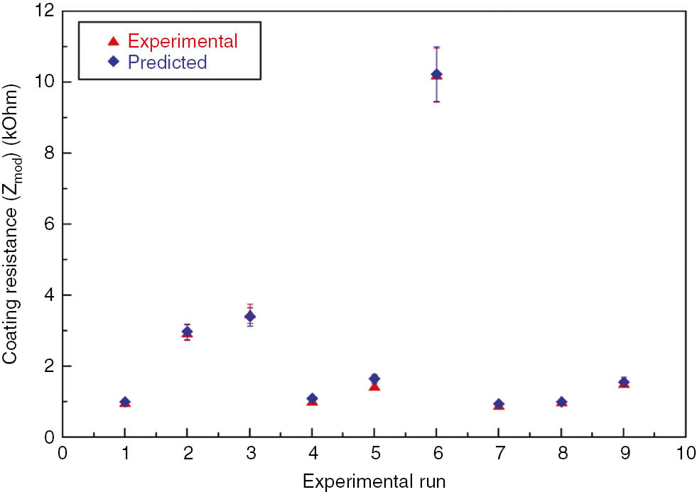
Experimentally measured and predicted values of coating resistance.
Coating resistance=3.42 – 0.119 (current density)+0.141 (deposition time) – 9.78 (wt % TiO2)
From the ANOVA analysis of the responses coating resistance and corrosion rate, it was found that the deposition time influences the phosphate coating process by 60%, followed by current density 18.8% and wt % TiO2 2.48%. It is expected from the above exercise that increased deposition time increases the coating weight by increasing coating thickness. However, a too high deposition time makes the coating to lower down and spill off easily because of attainment of the equilibrium state, which, in turn, causes the coating to be a less stable.
3.4 Comparative study of coatings deposited chemically and electrochemically
In this section, comparison of phosphate coatings deposited by chemical and electrochemical means is discussed. Table 7 shows the potentiodynamic polarization and EIS results for these coatings are comparable. It can be inferred from the table that the electrodeposited zinc phosphate coating using 0.5 g/l of nano-TiO2 reflects the formation of thick coatings.
Comparative study between conventional phosphate coatings and electrodeposited phosphate coatings.
| Type of coating | Chemical |
Electrochemical |
Bare LCS | ||
|---|---|---|---|---|---|
| Without nano-TiO2 | With nano-TiO2 | Without nano-TiO2 | With nano-TiO2 | ||
| Corrosion rate (mpy) | 4.2 | 3.5 | 8 | 1.38 | 14 |
| Coating resistance (kΩ) | 3.5 | 5.48 | 1.4 | 10.21 | – |
| Thickness (μm) | 3.5 | 6 | 4.85 | 8.5 | – |
The corrosion rate of nano-TiO2 containing the electrodeposited phosphate-coated sample was found to be 1.38 mpy, while it was 3.5 mpy for the nano-TiO2-containing phosphate-coated sample obtained by chemical deposition and can be attributed to reduction in the porosity of electrodeposited coatings. The existence of open pores is the major problem in phosphate coatings and, thus, affects the coating/substrate interface. Since the corrosion reaction intends to occur mostly at the coating/substrate interface, the determination of coating porosity becomes extremely important. As the first of its kind, this current campaign investigates the role of nano-TiO2 particles in coating porosity. Thus, the performance evaluation of these coatings can be carried by electrochemical measurements. The coating porosity can be estimated using Equation 7 (Aromaa et al., 1991; Creus et al., 2000; Vanessa de Freitas et al., 2006).
where Rps is the polarization resistance of the sample, Rp is the polarization resistance of the coated sample obtained from the EIS study, ΔEcorr is the potential difference between the sample and the coated sample and βa is the anodic Tafel constant obtained from the potentiodynamic polarization study. As the first of its endeavor, the porosity of nano-TiO2-containing electrodeposited-coated samples (~0.10%) was found to be lower than that of chemically deposited nano-TiO2-containing phosphate-coated samples (0.32%). The optimization studies revealed that the deposition time leads to the formation of thick coatings. However, it is worth mentioning here the significant observation made by Jegannathan et al. (2006a,b), that too much deposition time will make the coating unstable and breakdown could happen more easily. The authors truly believe that the obtained results are in agreement with the experimental observation of Shibli and Chacko (2011). The EIS results revealed a low coating capacitance in all the electrodeposited nano-TiO2 phosphate-coated samples. This will further oppose the penetration of external agencies (i.e. electrolyte or water), which minimizes the dissolution of zinc, thus increasing the corrosion resistance.
3.5 Multiobjective optimization of coating process parameters
The main motto of this work is to achieve maximum coating resistance and minimum corrosion rate for the optimal sets of input controlled process variables. However, coating resistance and corrosion rates are opposite output responses. So, multiobjective optimization helps in this regard. It uses the Taguchi signal-to-noise ratio to predict the rank of the input controlled process parameters, which contributes to the coating process significantly. This signal-to-noise ratio is of importance in this Taguchi method.
As signal should always be maximum and noise should be minimum, provision was made such that the signal-to-noise ratio should always be larger. So, selecting a larger better signal-to-noise ratio (Figure 13), the optimal setting of the process variables can be proposed (Table 8).
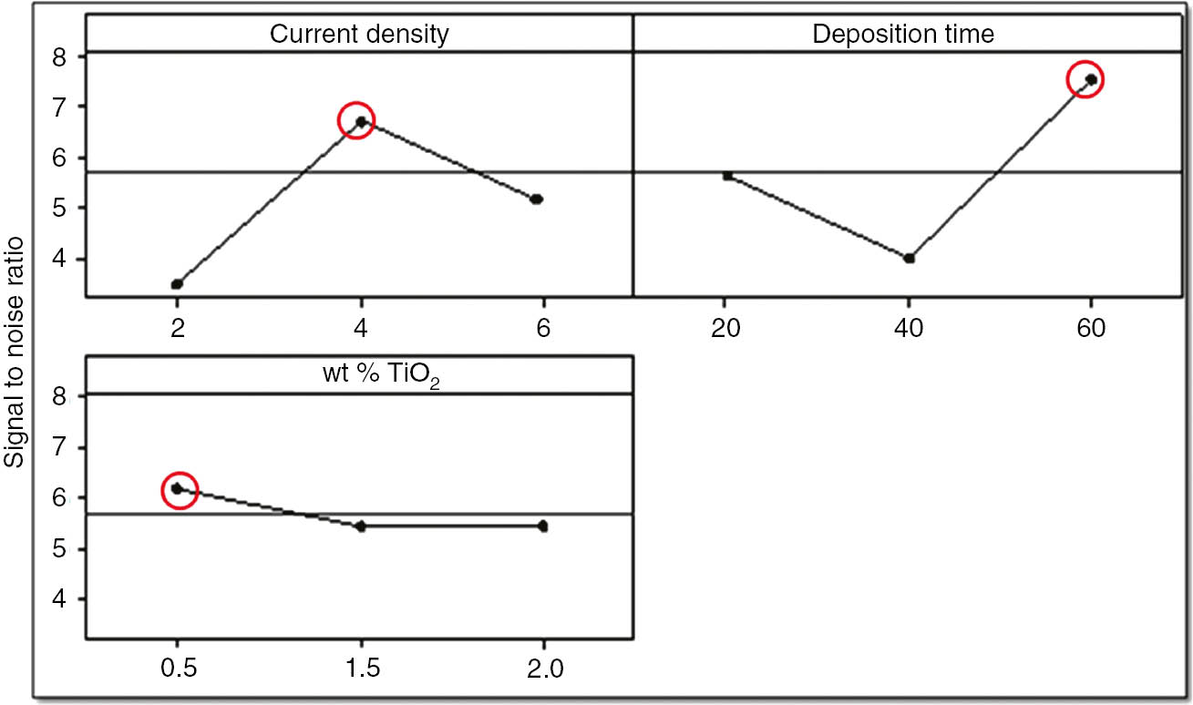
Signal to noise ratio for optimal setting of process variables.
Response table for signal-to-noise ratio and rank of each process variable.
| Level | 1 | 2 | 3 | Delta | Rank |
|---|---|---|---|---|---|
| Current density | 3.451 | 6.714 | 5.10 | 3.263 | 2 |
| Deposition time | 5.628 | 3.946 | 7.551 | 3.605 | 1 |
| wt % of nano-TiO2 | 6.236 | 5.444 | 5.445 | 0.792 | 3 |
Current density of 4 mA/cm2 with deposition time of 60 min and 0.5 wt % of nano-TiO2 gave the maximum coating resistance and minimum corrosion rate. So, to confirm these results, a confirmation test was taken, and both EIS and potential polarization studies were carried out. It was found that confirmation test results are in agreement with previous results.
In this work, an attempt has been made to propose optimal settings of input process parameters for the evaluation of effective corrosion protection performance of zinc phosphate coatings electrodeposited by anodic electrochemical treatment. Use of the Taguchi method was found to be very significant in performing the experiments and to achieve the maximum coating resistance (10.21 kΩ) and the minimum corrosion rate (1.38 mpy). The optimal settings of input process variables for the aforementioned output response could be proposed at respective levels of current density (4 mA/cm2), deposition time (60 min) and 0.5 wt % of nano-TiO2. Confirmation test and ANOVA analysis of the same set of input process variables were carried out to verify the accuracy and correctness of regression. The coating resistance and corrosion rate of the optimized sample in the confirmation run was found to be ~9.75 kΩ and 1.28 mpy, respectively, which again confirm that the results were in agreement. Further, the improvement in the signal-to-noise ratio was observed from 3.605 to 4.125 (Table 8), which is approximately 12.60% of the original.
4 Conclusions
As the first of its kind, this paper evaluates the corrosion protection performance of nano-TiO2-containing zinc phosphate coatings electrodeposited by anodic electrochemical treatment with emphasis on the optimization of input process variables using the Taguchi technique. The electrochemical deposition of these coatings on oxidizable surfaces of metals and alloys using a suitable electrode is possible. However, a simple zinc phosphate coating seems inadequate to provide protection for durable service life in aggressive environments, where localized breakdown of these coatings occurs easily. The detailed experimental analysis along with multiobjective optimization and critique presented in the above section leads to the following conclusions, as listed below.
A well-crystallized zinc phosphate coating was observed to be deposited by electrodeposition serving current density of 2, 4 and 6 mA/cm2 and deposition time of 20, 40 and 60 min on AISI 1015 LCS in a phosphating bath containing nano-TiO2. In comparison with chemically deposited phosphate layer on AISI 1015 carbon steel (Bagal et al., 2018), increased mass deposition was observed to be associated to the phosphate layer obtained by electrodeposition. Thus, this outcome specifies faster, higher and economical phosphating process.
The continuous monitoring of the time-potential curve during the formation of the phosphate layer reveals the phosphate coating mechanism, which can be identified in three steps: rapid increase in potential and coating weight immediately after immersion of the sample in phosphating bath, followed by nucleation and growth of crystallized zinc phosphate and, last, a complete surface coverage of sample by a dense spiculate zinc phosphate. The addition of nano-TiO2 in the phosphate bath helps reduce the porosity in phosphate coating.
The XRD analysis confirms the main phases of hopeite (Zn3(PO4)2.4H2O) and phosphophylite (Zn2FE(PO4)2.4H2O) and the trace of metallic zinc in the deposited phosphate layer. The visual appearance of these coatings is also studied. The SEM studies revealed the formed phosphate coating has a needle-like crystal structure. The presence of nano-TiO2 was confirmed from the EDX studies. The phosphate layer formed with the incorporation of nano-TiO2 in the phosphating bath shows a better surface coverage and thicker, homogeneous and more stable coatings.
The electrochemical characterization of electrodeposited nano-TiO2-containing phosphate layers exhibits a high corrosion resistance in 3.5% NaCl electrolyte as demonstrated by potentiodynamic polarization measurements. The EIS results support the potentiodynamic polarization measurements and depicts high corrosion efficiency of phosphate coatings. However, the addition of nano-TiO2 is expected to offer superior corrosion protection as the corrosion rate of nano-TiO2-containing phosphate coatings on LCS was observed to be 1.38 mpy, which is 6 times lesser than the normal zinc phosphate coatings (~8 mpy) and 12 times than the bare LCS (~14 and ~16 mpy as per industry standard). From the optimization studies, use of the Taguchi method was found to be very significant here in this work, as 27 experimental configurations were reduced to 9, giving the optimal settings of process variables. The ANOVA analysis reveals that deposition time plays a significant role in the anodic electrodeposition process (60%), followed by current density (18.8%). It was observed from the experiments that current density of 4 mA/cm2, deposition time of 60 min and 0.5 wt % of nano-TiO2 (experiment no. 6 in Table 4) will give maximum coating resistance and minimum corrosion rate. It can be concluded from the above aforementioned studies that the limited scope of anodic treatment reveals the addition of various sealing agents in phosphating bath for improved corrosion resistance and more economical advantages of these coatings and is regarded as open for the future advancement of this work.
Acknowledgments
The authors wish to express their thanks to Prof. B. B. Ahuja, Director, College of Engineering, Pune. The authors are also grateful to Dr. N. B. Dhokey, Head of the Department of Metallurgy and Materials Science, College of Engineering, Pune. V.S.K. gratefully acknowledges the ethical support from Prof. A. S. Adkine, Assistant Professor, Shreeyash College of Engineering and Technology, Aurangabad, by availing the software facilities.
-
Funding: The authors declare that there is no funding received (in any form) for this research/publication of this work and otherwise.
-
Conflicts of interest: The authors declare no potential conflicts of interest with respect to the research, authorship, and/or publication of this article.
References
Ahmad N, MacDiarmid AG. Inhibition of corrosion of steels with the exploitation of conducting polymers. Synth Metals 1996; 78: 103–111.10.1016/0379-6779(96)80109-3Search in Google Scholar
Akhtar AS, Susac D, Glaze P, Wong KC, Mitchell KAR. The effect of Ni2+ on zinc phosphating of 2024-T3 Al alloy. Surf Coat Tech 2004; 187: 208–215.10.1016/j.surfcoat.2004.02.044Search in Google Scholar
Aromaa J, Ronkainen H, Mahiout A, Hannula SP, Leyland A, Matthews A, Matthes B, Broszeit E. A comparative study of the corrosion performance of TiN, Ti (B, N) and (Ti, A1) N coatings produced by physical vapour deposition methods. Mater Sci Eng A 1991; 140: 722–726.10.1016/0921-5093(91)90503-FSearch in Google Scholar
ASTM A754, Standard Method for Coating Weight of Metallic Coatings on steel. West Conshohocken, PA: ASTM International, 2018.Search in Google Scholar
Bagal NS, Kathavate VS, Deshpande PP. Nano TiO2 phosphate conversant coatings – a chemical approach. Electrochem Energy Tech De Gruyter 2018; 4: 47–54.10.1515/eetech-2018-0006Search in Google Scholar
Banczek EP, Rodrigues PRP, Costa I. Investigation on the effect of benzotriazole on the phosphating of carbon steel. Surf Coat Tech 2006; 201: 3701–3708.10.1016/j.surfcoat.2006.09.003Search in Google Scholar
Banczek EP, Rodriguez PRP, Costa I. The effects of niobium and nickel on the corrosion resistance of the zinc phosphate layers. Surf Coat Tech 2008; 202: 2008–2014.10.1016/j.surfcoat.2007.08.039Search in Google Scholar
Bhar GN, Debnath NC, Roy S. Effects of calcium ions on the morphology and corrosion resistance of zinc phosphate steel. Surf Coat Tech 1988; 35: 171–179.10.1016/0257-8972(88)90066-7Search in Google Scholar
Brooman EW. Modifying organic coatings to provide corrosion resistance – part III: organic additives and conducting polymers. Metal Finishing 2002; 10: 104–110.10.1016/S0026-0576(02)80446-9Search in Google Scholar
Bustamante G, Fabri-Miranda FJ, Margarit ICP, Mattos OR. Influence of pre phosphating on painted electrogalvanized steel. Prog Org Coat 2003; 46: 84–90.10.1016/S0300-9440(02)00214-XSearch in Google Scholar
Chen T-T, Ke S-T, Liu Y-M, Hou K-H. The study on optimizing the zinc phosphate conversion coating process and its corrosion resistance. J C.C.I.T. 2006; 34: 56–62.Search in Google Scholar
Creus J, Mazille H, Idrissi H. Porosity evaluation of protective coatings onto steel through electrochemical techniques. Surf Coat Tech 2000; 130: 224–232.10.1016/S0257-8972(99)00659-3Search in Google Scholar
De Berry DW. Modification of the electrochemical and corrosion behavior of stainless steels with an electroactive coating. J Electrochem Soc 1985; 132: 1022–1026.10.1149/1.2114008Search in Google Scholar
Deshpande PP, Jadhav NG, Gelling VJ, Sazou D. Conducting polymers for corrosion protection: a review. J Coat Tech Res 2014; 14: 473–494.10.1007/s11998-014-9586-7Search in Google Scholar
Diaz B, Freire L, Mojio M, Novoa XR. Optimization of conversion coatings based on zinc phosphate on high strength steels with enhanced barrier properties. J Electroanalyt Chem 2015; 737: 174–183.10.1016/j.jelechem.2014.06.035Search in Google Scholar
Fontana MG. Corrosion engineering, 3rd ed., New Delhi: Tata McGraw Hill Education Private Ltd., 2005.Search in Google Scholar
Gentil V. Corrosion. LTC, 3rd ed., 1987; 319 (In Portuguese).Search in Google Scholar
Jegannathan S, Sankara Narayanan TSN, Ravichandran K, Rajeshwari S. Performance of zinc phosphate coatings obtained by cathodic electrochemical treatment in accelerated corrosion tests. Electrochem Acta 2005; 51: 247–256.10.1016/j.electacta.2005.04.020Search in Google Scholar
Jegannathan S, Sankara Narayanan TSN, Ravichandran K, Rajeshwari S. Evaluation of corrosion resistance of phosphate coatings obtained by anodic electrochemical treatment. Prog Org Coat 2006a; 57: 392–399.10.1016/j.porgcoat.2006.09.023Search in Google Scholar
Jegannathan S, Sankara Narayanan TSN, Ravichandran K, Rajeshwari S. Formation of zinc phosphate coating by anodic electrochemical treatment. Surf Coat Tech 2006b; 200: 6014–6021.10.1016/j.surfcoat.2005.09.017Search in Google Scholar
Kouisni L, Azzi M, Zertoubi M, Dalard F, Maximovitch S. Phosphate coatings on magnesium alloy AM60 part 1: study of the formation and the growth of zinc phosphate films. Surf Coat Tech 2004; 185: 58–67.10.1016/j.surfcoat.2003.10.061Search in Google Scholar
Lian JS, Li GY, Niu LY, Gu CD, Jiang ZH, Jiang Q. Electroless Ni–P deposition plus zinc phosphate coating on AZ91D magnesium alloy. Surf Coat Tech 2006; 200: 5956–5962.10.1016/j.surfcoat.2005.09.007Search in Google Scholar
Lorin G. Phosphating of metals. Middlesex: Finishing Publications, Ltd., 1974: 4.Search in Google Scholar
Machu W. Phosphate coating and its scientific fundamental. Mettalwirtschaft 1943; 22: 481–487.Search in Google Scholar
Meszaros L, Lendvay-Gyorik G, Lengyel B. Study of coverage of phosphated steel by electrochemical method. Mater Chem Phys 1989; 23: 267–286.10.1016/0254-0584(89)90071-0Search in Google Scholar
Rani N, Singh AK, Alam S, Bandyopadhyay N, Denys MB. Optimization of phosphate coating properties on steel sheet for superior paint performance. J Coat Tech 2012; 9: 629–636.10.1007/s11998-012-9395-9Search in Google Scholar
Niu LY, Jiang ZH, Li GY, Gu CD, Lian JS. A study and application of zinc phosphate coating on AZ91D magnesium alloy. Surf Coat Tech 2006; 200: 3021–3026.10.1016/j.surfcoat.2004.10.119Search in Google Scholar
Ogle K, Tomand A, Meddahi N, Wolpers M. The alkaline stability of phosphate coatings I: ICP atomic emission spectro electrochemistry. Corros Sci 2004; 46: 979–995.10.1016/S0010-938X(03)00182-3Search in Google Scholar
Rout TK, Pradhan HK, Venugopalan T. Enhanced forming properties of galvannealed steel sheet by polymanganese phosphate coating. Surf Coat Tech 2006; 201: 3496–3501.10.1016/j.surfcoat.2006.07.260Search in Google Scholar
Sankara Narayanan TSN. Surface pretreatment by phosphate conversion coatings – a review. Rev Adv Mat Sci 2005; 9: 130–177.Search in Google Scholar
Shibli SMA, Chacko F. Development of nano TiO2-incorporated phosphate coatings on hot dip zinc surface for good paintability and corrosion resistance. Appl Surf Sci 2011; 257: 3111–3117.10.1016/j.apsusc.2010.10.125Search in Google Scholar
Sinha PK, Feser R. Phosphate coating on steel surfaces by an electrochemical method. Surf Coat Tech 2002; 161: 158–168.10.1016/S0257-8972(02)00521-2Search in Google Scholar
Sun X, Susac D, Li R, Wong KC, Foster T, Mitchell KAR. Some observations for effects of copper on zinc phosphate conversion coatings on aluminium surfaces. Surf Coat Tech 2002; 155: 46–50.10.1016/S0257-8972(02)00027-0Search in Google Scholar
Twite RL, Bierwagen GP. Review of alternatives to chromate for corrosion protection of aluminum aerospace alloys. Prog Org Coat 1998; 33: 91–100.10.1016/S0300-9440(98)00015-0Search in Google Scholar
Vanessa FCL, Geraldo FAR, Carlos RA, Tulio M. Electrochemical impedance spectroscopy and linear polarization applied to evaluation of porosity of phosphate conversion coatings on electro galvanized steels. Appl Surf Sci 2006; 253: 2875–2884.10.1016/j.apsusc.2006.06.030Search in Google Scholar
Weng D, Jokiel P, Uebleis A, Boehni H. Corrosion and protection characteristics of zinc and manganese phosphate coatings. Surf Coat Tech 1996; 88: 147–156.10.1016/S0257-8972(96)02860-5Search in Google Scholar
Wessling B. Passivation of metals by coating with polyaniline: corrosion potential shift and morphological changes. Adv Mater 1994; 6: 226–228.10.1002/adma.19940060309Search in Google Scholar
Whitten MC, Lin C-T. An in situ phosphatizing coating on 2024T3 aluminum coupons. Prog Org Coat 2000; 38: 151–162.10.1016/S0300-9440(00)00101-6Search in Google Scholar
Wolynec S. Tecnicas Electroquimicas em Corrosao, EDUSP – Editora da Universidade de Sao Pulo, Sao Paulo. 2003; 166.Search in Google Scholar
Yantapure M, Deshpande P, Vagge S. Effect of current density and deposition time on galvanostatic phosphating of low carbon steel. U P B Sci Bull Series B 2015; 77: 173–180.Search in Google Scholar
Zhang S-L, Chen H-H, Zhang X-L, Zhang M-M. The growth of zinc phosphate coatings on 6061-Al alloy. Surf Coat Tech 2008a; 202: 1674–1680.10.1016/j.surfcoat.2007.07.037Search in Google Scholar
Zhang S, Zhang X, Zhang M. Zinc phosphating of 6061-Al alloy using REN as additive. J Rare Earths 2008b; 26: 110–114.10.1016/S1002-0721(08)60048-4Search in Google Scholar
©2019 Walter de Gruyter GmbH, Berlin/Boston
Articles in the same Issue
- Frontmatter
- In this issue
- Reviews
- An updated review on TiNi alloy for biomedical applications
- Severity of corrosion under insulation (CUI) to structures and strategies to detect it
- Original articles
- Corrosion protection performance of nano-TiO2-containing phosphate coatings obtained by anodic electrochemical treatment
- Influence of heat treatment on the corrosion properties of CuAlMn shape memory alloys
- Annual reviewer acknowledgement
- Reviewer acknowledgement Corrosion Reviews volume 37 (2019)