Effect of non-return valves on the time-of-arrival of new medication in a patient after syringe exchange in an infusion set-up
-
Maurits K. Konings

 ,
Robin Gevers
,
Robin Gevers

Abstract
The presence of a non-return valve in an infusion set-up is expected to affect the time-of-arrival of new medication in a patient after syringe exchange. Using Computational Fluid Dynamics (CFD) we have studied the flow through a typical non-return valve, focusing on two separate effects: (A) the overall delay in the time-of-arrival, and (B) timing effects due to the distortion of the Poiseuille flow profile in the non-return valve. The results show that (A) the additional delay in time-of-arrival of new medication, caused by the non-return valve alone, corresponds to the delay that would be caused by 11.2 cm of extra infusion line instead of the valve, and that (B) the non-Poiseuille flow profile inside the non-return valve gives rise to an extra slow wash-out of the last portion of the remnant fluid of the old medication. We conclude that awareness of these extra delays may be important for clinicians in certain time-critical situations.
Introduction
It has been known for many decades now that when a patient is connected to an infusion line, the risks of fluids travelling in the opposite direction (i.e. going away from the patient instead of going towards the patient) should be mitigated [1, 2]. To this end, many infusion sets are equipped with a non-return valve (also referred to as one-way valve, anti-reflux valve, or check valve) that makes it impossible for fluids to travel in the wrong direction. Evidently, the internal mechanisms inside such a non-return valve will involve structures that are not present in the standard infusion lines themselves, and may deviate substantially from the cylindrically symmetric nature of the inner lumina of infusion lines and catheters.
However, when a clinician performs e.g. a syringe exchange at the infusion pump, he or she is trained to make an estimate of the time delay between the moment that the pump starts pushing the new medication into the infusion system, and the moment that the first 5% of the new medication has actually entered the bloodstream of the patient after having travelled through the infusion lines and catheter. The clinician will make this estimate based on the Poiseuille flow profile: rules of thumb that are valid for the standard, cylindrically symmetric tubing that constitutes the combination of infusion line and catheter. One of those rules of thumb is that the first molecules of the new medication will arrive already at half the time that would be obtained by simply dividing the internal volume (of the catheter-infusion line combination) by the flow rate. This 0.5 factor is based on the fact that, in a Poiseuille flow, at the centerline of the tubing the fluid travels at twice the average velocity of the entire volume.
The addition of extra elements into the infusion system, such as a non-return valve, makes it necessary to amend these rules of thumb. This is due to the fact that, although the flow inside a non-return valve is still laminar, it is not cylindrically symmetric, and therefore deviates substantially from the Poiseuille flow on which the rules-of-thumb rely.
Furthermore, since devices such as a non-return valve may have large internal volumes with respect to the relatively thin infusion lines, there may be a significant extra delay in the time-of-arrival of the first molecules of the new medication in the patient after a syringe exchange.
Finally, if the total flow resistance of the system is increased from R to R + ΔR due to the insertion of a non-return valve (having an intrinsic resistance of ΔR) into the infusion line system, then the time constant of the start-up delay due to the compliance effect [3] changes as well, i.e. it changes from RC to (R + ΔR)C. Therefore, the ΔR, of the specific non-return valve that has been used in the simulations, has been assessed as well (see Results section).
This study aims to answer two crucial questions regarding the effects of non-return valves on the arrival of medications into the bloodstream of patients. The first question (A) concerns the time of arrival of the first molecules of the new medication. We wish to quantify the length of an imaginary, additional piece of infusion line that would produce the same extra delay as the non-return valve.
The second question (B) concerns the washing out of the (unwanted) remnant of the previous medication that is still present directly after the syringe exchange. It is expected that the aforementioned deviation from the Poiseuille flow in the non-cylindrically symmetric internal structure of the non-return valve may give rise to a particularly slow wash-out of the last portion of the remnant fluid containing the old medication.
The rest of this paper is organised as follows. In Methods, the methodology followed to answer questions (A) and (B), formulated directly above, is presented.
In the Results section, the outcome of the CFD analysis is presented and questions (A) and (B) are answered. Finally, in the Conclusions section, the clinical implications of these findings are discussed.
Methods
It is well known [3, 4] that the Reynolds numbers in medical infusion sets are such that the flow is always laminar. We highlight that all calculations in this paper are based on data from Computational Fluid Dynamics (CFD) [5, 6] simulations using a geometrical model of a simplified non-return valve.
Geometry and mesh of non-return valve
As an example of a widely used non-return valve we chose the one included in the IV-set: IV SLOTSET NEO WKZ UMCU (Article number: M18065), product of IMF (IMPROMEDIFORM GmbH, Lüdenscheid, Germany), see Figure 1. A simplified geometry of the valve was created based on measurements of the key dimensions, since a drawing from the manufacturer was not available. A cross-section of the 3D CAD model of the valve geometry along with its dimensions is shown in Figure 2. We highlight that only the internal dimensions are needed for the generation of an appropriate CFD model, and, therefore, only those are included in Figure 2.
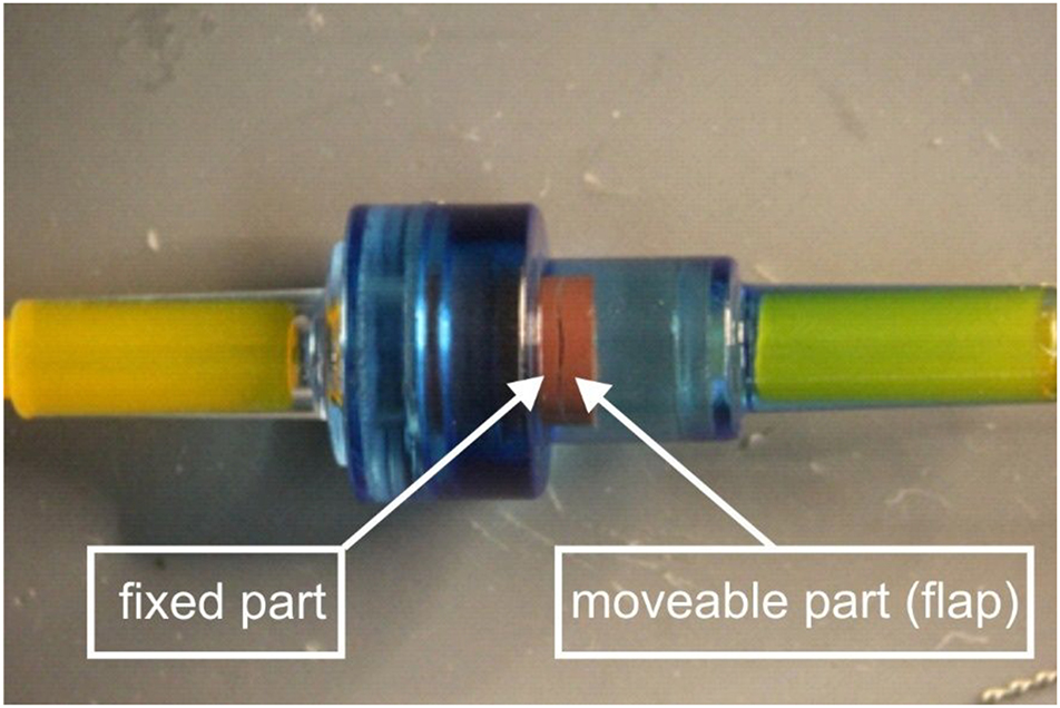
Photograph (close-up) of a clinically-used non-return valve employed in this study. The dark, slit-like, narrow opening visible in the red rubber structure corresponds to an opening angle of approximately 1°, between the moveable, hinged part (flap) of the red rubber and the fixed part. The hinge itself, connecting the moveable part of the red rubber to the fixed part is located at the other side and hence not visible in this photo.

3D CAD model of the simplified non-return valve geometry used in this study. (Top) Cross-section along the symmetry plane and (bottom) view of the back of the flap. Only the internal dimensions (in mm) are noted since those are required for the generation of the computational model; the wall thickness illustrated is arbitrary. A geometry with a flap opening higher than 1° is depicted here for better visualisation. The location X=0.030 m is located outside this figure to the right.
From various close-up photos of the non-return valve taken for a wide range of flow rates, it was concluded that in all clinically feasible flow rates, the opening angle of the flap is of about 1°. Note that in order to have fully developed flow profile, the geometry was extended by the addition of upstream and downstream straight pipes.
A half symmetry computational model was generated in order to reduce the number of computational cells. An unstructured mesh of 3.9 million cells was constructed, consisting of polyhedral elements in the bulk region and poly-prisms in the boundary layer. The total model incorporated not only the check valve as shown in Figure 2, but also ample length of straight tubing (infusion line) extending more than 150 mm to the left as well as to the right, parallel to the X-axis and connected to the orifice (inlet) on the left in Figure 2, as well as the orifice (outlet) on the right, respectively. The inner diameter of the infusion line was 0.652 mm. The grid had two refinement regions to better capture the flow behaviour in the check valve and particularly in the narrow flap opening. Figure 3 depicts the part of the computational mesh in which the local mesh refinement along the check valve is shown.

Computational mesh of the simplified non-return valve geometry. View of the mesh focusing on the valve. The fluid volume of the half-symmetry model is discretised using high quality polyhedral elements for the bulk region and poly-prisms to capture the boundary layer. The two refinement zones, i.e. one surrounding the flap and a denser one on the narrow flap opening, are visible due to the reduced cell size on each region. Again, the location X=0.030 m is located outside this figure to the right.
CFD modelling
The steady-state laminar flow simulation was carried out using the commercial CFD software ANSYS Fluent 2021 R1. The incompressible single-phase flow is governed by the Navier–Stokes equations (NSEs) characterised by low Reynolds numbers. The numerical solution of the NSEs was obtained using the coupled algorithm and all the discretisation schemes were second order. A fixed mass flow rate of 5 mL/h was imposed at the inlet, a zero-gauge pressure at the outlet and no-flux condition was imposed at the symmetry plane. The no-slip boundary condition was utilised for the solid walls. The medication fluid considered in this study had a density of 1,005.3 kg/m3 and viscosity 0.00102 Pa s.
Poiseuille flow and equivalent tube length for dose arrival times
The flow streamline data generated from the CFD simulation is used in the calculations that follow. The cross-section at X=0.030 m, which represents a location in the tube segment well after the flow has passed through the non-return valve, has been analysed. Since this location X=0.030 m is located several cm to the right with respect to the section of the mesh that is shown in Figure 3, this location X=0.030 m is not visible in Figure 3.
The streamline data were used as an input, to calculate a general interpolation function over the cross-sectional area. The result was a set of approximately 2,000 equally sized surfaces covering the whole cross-sectional area, which allows for the production of a histogram indicating the number of flow elements travelling at specific speeds. This number of surfaces has been chosen for the sake of computational efficiency.
Furthermore, the CFD simulation provided the time that fluid particles travelling on a streamline require to reach the plane at X=0.030 m. This allowed the robust assessment of the equivalent length of infusion line that would cause the same extra delay as the non-return valve.
This equivalent length, L, of infusion line that replaces and “mimics” the non-return valve, was calculated using a least-square method for fitting the output of the valve (travel time for a large set of different streamlines calculated using CFD) to the output (travel time for the same large set of streamlines) produced by the Poiseuille flow in the equivalent piece of infusion line of length L that replaces the valve.
Once this equivalent length L of infusion line was established, the resulting histogram, based on a Poiseuille flow profile using the original length plus the “equivalent length”, was compared to the original histogram of the actual flow through the non-return valve based on the data derived from the CFD simulation.
In this way, the effects of the non-Poiseuille flow inside the non-return valve were compared with its mimicking counterpart producing the same overall delay. Therefore, any accelerations or delays in the wash-out of the last portion of the remnant fluid became visible. This process answered question (B) from the introduction.
Results and discussion
The basis of all calculations giving the answers to the questions (A: the time of arrival of the first molecules of the new medication into the patient and B: the extra amount of time needed to wash away the remains of the old medication due to the presence of the non-return valve) posed at the introduction is provided by the output of the CFD simulations.
We therefore first present the computational results of the CFD simulations, and subsequently provide the analysis that answers question A, and B, respectively.
CFD analysis
The velocity streamlines shown in Figure 4 are examined. As expected, as the fluid goes through the first widening section of the valve, it gradually decelerates. At the straight section just before the flap, the profile is nearly developed. While the fluid is forced to pass through the narrow flap opening it accelerates, as the mass continuity dictates. Immediately after the flap opening, the fluid velocity reduces significantly until it is forced to enter the narrower straight tube section again. We highlight that due to the laminar nature of the flow, the fluid tends not to have any lateral mixing. The visualisation of the flow streamlines confirms that the adjacent fluid layers slide past one another, with no disruption between the layers.

Flow streamlines coloured by the velocity magnitude for the simplified non-return valve with 1° flap opening. The flow goes from left to right.
Equivalent tube length for dose arrival times of non-return valve
Using the procedures described in the Methods section, we obtained an equivalent tube length for the additional delay in arrival time due to the non-return valve. Based on the numerical simulation, we calculated that the length of the additional tube mimicking the non-return valve was equal to 11.2 cm. Consequently, given the flow rate of 5 mL/h and the inner diameter of the infusion line of 0.652 mm, the insertion of this specific type of non-return valve into the infusion line will give rise to an additional time delay Δtvalve that is equal to:
which corresponds to Figure 5A in [7]. This value answers question (A) from the Introduction.
Effect of non-Poiseuille laminar flow profile
As mentioned in the Introduction, the internal geometry of the non-return valve is expected to have an unfavourable effect on the wash-out of the remnant fluid, leading to an extra delay.
This effect is quantified in Figure 5, where the histogram gives the fraction of the total number of fluid particles (vertical axis) that require a certain amount of time (horizontal axis) to reach the plane X=0.030 m (which corresponds to Figure 5B in [7]). The result from the CFD simulation is rendered in yellow, whereas the light blue histogram represents the Poiseuille equivalent, in which the valve has been replaced by the “equivalent tube”, producing the same overall delay.
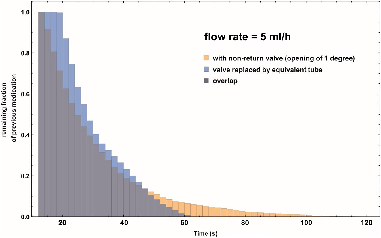
Combined histogram of the remaining fraction of the previous, “old” medication, at cross-section X=0.030 m as a function of the pumping time of the infusion pump after a syringe exchange. Note that this cross-section is located at the downstream straight pipe section, well after the non-return valve. Flow rate is 5 mL/h. Yellow histogram: The remaining fraction as function of time using the CFD simulation data of the non-return valve. Light blue histogram: The remaining fraction as function of time, using a Poiseuille flow profile and the equivalent tube length as a substitute for the non-return valve. Dark purple histogram: Area of overlap of the yellow and light blue histograms.
The yellow “tail” that is visible in Figure 5 indicates that the non-return valve is responsible for an extra period of time where the “old” medication is still lingering inside its volume. The above analysis answers question (B) from the introduction.
Effect of added flow resistance due to the non-return valve
The flow resistance ΔR of the IMPROMEDIFORM non-return valve used in the simulations has been measured, yielding ΔR=987.4 Pa/(mL/h). In combination with the standard syringe commonly used in our hospital and elsewhere, i.e. the disposable plastic B. Braun Omnifix 50 mL syringe (B.Braun, Melsungen, Germany) having a Compliance C equal to 1.5 10−5 mL/Pa, this yields an increase in the RC-time constant of: ΔtRC = C ΔR = 53 s.
Conclusions
This study investigated the effects of non-return valves on the estimated time of arrival of new medication after a syringe exchange.
The length of the additional infusion line that would lead to the same delay in the arrival of medication as the non-return valve was calculated to be equal to 11.2 cm. The length of the additional tubing was considerably larger than the length of the non-return valve itself. This result may be of use to clinicians when applying the “rule-of-thumb” [7, 8] for predicting the point in time when the first molecules of a new medication will arrive in the blood stream of a patient.
In addition to the above, the results from the CFD calculations indicate that the deviation from the Poiseuille flow profile inside the non-cylindrically symmetric geometry of the non-return valve gives rise to an extra slow wash-out of the last portion of the remnant fluid of the old medication after a syringe exchange.
In summary, we conclude that the typical non-return valve studied in this paper gives rise to a considerable additional delay in the time-of-arrival of new medication in a patient after syringe exchange in an infusion set-up, and therefore awareness of this extra delay may be important for clinicians in certain time-critical situations.
Funding source: European Metrology Programme for Innovation and Research
Award Identifier / Grant number: 18 HLT08 MeDDII
-
Acknowledgments: The authors wish to thank Lefki Germanou from TÜV SÜD East Kilbride, Scotland, United Kingdom, for her excellent work on the CFD computations, and Les Wales for measuring the resistance of the non-return valve.
-
Research funding: This work performed under 18 HLT08 MeDDII project has received funding from the EMPIR programme co-financed by the Participating States and from the European Union’s Horizon 2020 research and innovation programme.
-
Author contributions: All authors have accepted responsibility for the entire content of this manuscript and approved its submission. MK co-developed the concept described in the paper, performed data analysis, and wrote the manuscript; RG and SM performed measurements on the non-return valve; AT co-developed the concept, coordinated the research and edited the manuscript.
-
Competing interests: Authors state no conflict of interest.
-
Informed consent: Not applicable.
-
Ethical approval: Not applicable.
References
1. Lannoy, D, Décaudin, B, Dewulf, S, Simon, N, Secq, A, Barthélémy, C, et al.. Infusion set characteristics such as antireflux valve and dead-space volume affect drug delivery: an experimental study designed to enhance infusion sets. Anesth Analg 2010;111:1427–31. https://doi.org/10.1213/ane.0b013e3181f66ee3.Search in Google Scholar
2. van der Eijk, AC, van der Plas, AJ, van der Palen, CJ, Dankelman, J, Smit, BJ. In vitro measurement of flow rate variability in neonatal IV therapy with and without the use of check valves. J Neonatal Perinat Med 2014;7:55–64. https://doi.org/10.3233/npm-1475213.Search in Google Scholar
3. Snijder, RA, Konings, MK, Lucas, P, Egberts, TC, Timmerman, AD. Flow variability and its physical causes in infusion technology: a systematic review of in vitro measurement and modeling studies. Biomed Eng-Biomed Tech 2015;60:277–300. https://doi.org/10.1515/bmt-2014-0148.Search in Google Scholar PubMed
4. Carlson, JE, Hedlund, LJ, Trenkner, SW, Ritenour, R, Halvorsen, RA. Safety considerations in the power injection of contrast media via central venous catheters during computed tomographic examinations. Invest Radiol 1992;27:337–40. https://doi.org/10.1097/00004424-199205000-00001.Search in Google Scholar PubMed
5. Jain, K, Jiang, J, Strother, C, Mardal, KA. Transitional hemodynamics in intracranial aneurysms – comparative velocity investigations with high resolution lattice Boltzmann simulations, normal resolution ANSYS simulations MR Imaging. Med Phys 2016;43:6186. https://doi.org/10.1118/1.4964793.Search in Google Scholar PubMed
6. Goubergrits, L, Riesenkampff, E, Yevtushenko, P, Schaller, J, Kertzscher, U, Berger, F, et al.. Is MRI-based CFD able to improve clinical treatment of coarctations of aorta? Ann Biomed Eng 2015;43:168–76. https://doi.org/10.1007/s10439-014-1116-3.Search in Google Scholar PubMed
7. Konings, MK, Snijder, RA, Radermacher, JH, Timmerman, AM. Analytical method for calculation of deviations from intended dosages during multi-infusion. Biomed Eng Online 2017;16:18. https://doi.org/10.1186/s12938-016-0309-4.Search in Google Scholar PubMed PubMed Central
8. Timmerman, AM, Snijder, RA, Lucas, P, Lagerweij, MC, Radermacher, JH, Konings, MK. How physical infusion system parameters cause clinically relevant dose deviations after setpoint changes. Biomed Eng-Biomed Tech 2015;60:365–76.10.1515/bmt-2014-0139Search in Google Scholar PubMed
© 2022 the author(s), published by De Gruyter, Berlin/Boston
This work is licensed under the Creative Commons Attribution 4.0 International License.
Articles in the same Issue
- Frontmatter
- Guest Editorial
- Medical flow and dosing measurement metrology in drug delivery
- Special Issue Articles
- Metrology in health: challenges and solutions in infusion therapy and diagnostics
- Calibration methods for flow rates down to 5 nL/min and validation methodology
- Measurement of internal diameters of capillaries and glass syringes using gravimetric and optical methods for microflow applications
- In-line measurements of the physical and thermodynamic properties of single and multicomponent liquids
- Assessment of drug delivery devices working at microflow rates
- Calibration of insulin pumps based on discrete doses at given cycle times
- Development of a microfluidic electroosmosis pump on a chip for steady and continuous fluid delivery
- Effect of non-return valves on the time-of-arrival of new medication in a patient after syringe exchange in an infusion set-up
- Holographic PIV/PTV for nano flow rates–A study in the 70 to 200 nL/min range
- Unexpected dosing errors due to air bubbles in infusion lines with and without air filters