Musculoskeletal model-based control strategy of an over-actuated glenohumeral simulator to assess joint biomechanics
-
Jeremy Genter
Jeremy Genter is currently pursuing his PhD at the University of Basel and Zurich University of Applied Sciences, under the guidance of Prof. Mündermann and Prof. Baumgartner. He is closely collaborating with Prof. Rauter in the Department of Biomedical Engineering at the University of Basel.
 ,
Georg Rauter
,
Georg Rauter
Georg Rauter is Associate Prof. for Surgical Robotics at the BIROMED-Lab. His background is Mechanical Engineering (TU-Graz) and Mathematical and Mechanical Modeling (MATMECA, Bordeaux). In 2014 he received his PhD in robotics from ETH Zurich.
Prof. Müller is the current Head of the Department of Orthopaedics and Traumatology. He has expertise in the diagnosis and therapy of musculoskeletal disorders and orthopaedic surgery. He received his medical training at the University of Basel, Basel, Switzerland.
Prof. Mündermann is the Research Director of the Functional Biomechanics Research Group at the Department of Orthopaedics and Traumatology, University Hospital Basel, Basel, Switzerland. She received her PhD in Medical Sciences from the University of Calgary, Canada.
Prof. Baumgartner is Professor in Biomechanical Engineering and is the current head of the group of Biomechanics at the IMES Institute of Mechanical Systems. He received his PhD in 2009 in the field of Biomechanical Engineering from ETH, Zürich, Switzerland.

Abstract
Determining the acting shoulder and muscle forces in vivo is very complex. In this study, we developed a control strategy for a glenohumeral simulator for ex vivo experiments that can mimic physiological glenohumeral motion and overcome the problem of over-actuation. The system includes ten muscle portions actuated via cables to induce upper arm motion in three degrees of freedom, including scapula rotation. A real-time optimizer was implemented to handle the over-actuation of the glenohumeral joint while ensuring a minimum of muscle tension. The functionality of the real-time optimizer was also used to simulate different extents of rotator cuff tears. Joint reaction forces were consistent with in vivo measurements. These results demonstrate the feasibility and added value of implementing a real-time optimizer for using in vivo data to drive a shoulder simulator.
Zusammenfassung
Die Bestimmung der wirkenden Schultergelenks- und Muskelkräfte in vivo ist sehr komplex. In dieser Studie wurde eine Kontrollstrategie für einen glenohumeralen Simulator für ex vivo Experimente entwickelt, der die physiologischen glenohumeralen Bewegungen nachahmen und das Problem der Überaktuation lösen kann. Das System umfasst zehn Muskelsegmente, die über Motoren via Kabelzüge angesteuert werden, um die Oberarmbewegung in drei Freiheitsgraden, einschließlich der Skapularotation, zu induzieren. Ein Echtzeit-Optimierer wurde implementiert, um die Überaktuation des Glenohumeralgelenks zu lösen und gleichzeitig eine minimale Muskelvorspannung zu gewährleisten. Die Funktionalität des Echtzeit-Optimierers wurde auch genutzt, um verschiedene Grade von Rotatorenmanschettenrupturen zu simulieren. Die Gelenkreaktionskräfte stimmten mit den in vivo Messungen überein. Diese Ergebnisse zeigen die Machbarkeit und den Mehrwert der Implementierung eines Echtzeit-Optimierers für die Verwendung von in vivo Daten zur Steuerung eines Schultersimulators.
1 Introduction
The glenohumeral (GH) joint has the largest range of motion (RoM) in the human body facilitated by the size mismatch of the smaller glenoid fossa and the prominent condyle of the humerus. The GH joint can be considered as a joint with six degrees of freedom (DoF), three of which are rotational and three are translational DoF, that are actuated by 11 muscles [1]. This makes the joint an under-determined (in the context of optimization) or over-actuated system (in the context of control). In addition, the GH joint is also prone to instability due to the translational DoF. Various active (e.g., rotator cuff (RC) muscles) and passive (e.g., GH capsule) structures are involved in providing stability, which must be considered when studying the biomechanics of the GH joint [2], especially when the RC becomes dysfunctional for any reason.
The RC is the muscle group that provides most of the stability in the GH joint while allowing a large RoM. Untreated RC tears can cause weakness, pain, and/or limited RoM [3] and can alter joint biomechanics and cause pathological changes in the GH joint. In addition, RC tears can progress to other problems, such as shoulder impingement or even osteoarthritis [3].
Investigating the biomechanics of the GH joint during motion is challenging. Therefore, various GH experiments have been developed to mimic GH joint motion. Some of these experiments provide valuable insight into the passive biomechanics of the shoulder, including the role of the shape of the glenoid concavity [4], the strength of the GH capsule [5], and the stability during quasistatic positions of specific movements (e.g., in abduction and in position of late cocking phase of throwing [6]). Previous muscle-controlled simulators provide insights into the importance of active stabilizers (e.g., RC muscles) in surgical interventions (e.g., RC repair [7] and total reverse shoulder arthroplasty [8]). In addition, ex vivo experiments play a role in exploring the anatomical structures and their variability among specimens.
Most simulators are used in static experiments or are motion constrained [9]. However, some simulators allow for a free-hanging humerus, hence overcoming the static and constrained conditions. Different strategies have been pursued to control such an over-actuated system. In the most common strategy, a primary muscle is simulated by a position-controlled loader that determines the secondary muscle forces with constant force ratios [10, 11]. In another simulator [12], this strategy was improved by using variable muscle force ratios according to electromyographic (EMG) patterns [13], which may vary with disease and load. One alternative approach is to individually calibrate the displacement path profile of each muscle and control the motors according to these displacement profiles [14]. A significant drawback of this concept is that the under-determined joint motion is solved ambiguously. A more computationally expensive strategy entails the use of muscle force optimization [15–18], representing a promising approach as it utilizes a cost function to address over-actuation hence accounting for the underlying biomechanics. However, while this concept uses static muscle force optimization to minimize muscle activation, the optimization does not consider joint stability, and to date, this approach has not been widely used.
To date, it is unclear how muscles can be actuated most physiologically [1]. Static muscle force optimization is often used in numerical musculoskeletal modeling simulations [19]. Usually, muscle activation is minimized while the muscle still provides the required joint torque for the motion [19]. However, this optimization method results in greatly underestimated muscle forces of muscles spanning the GH joint, especially of the RC muscles that contribute to joint stability. The latest musculoskeletal GH models apply a constraint to the optimization process, which ensures that the line of action of the joint reaction force remains within the boundaries of the glenoid [20–22].
Here, we present a muscle-controlled GH simulator and its control concept using muscle force optimization and considering joint stability. In addition, a generalized controller is described that allows controlling different types of RC tears. Finally, we investigated this concept, present the performance of the motion for different RC tear types, and compare the simulator with in vivo data.
2 Methods
2.1 Mechanical system
The proposed control strategy and additional modification of the mechanics were implemented in our previously developed GH simulator [10] that consists of a scapula that rotates in the scapular plane and a 6-DoF GH joint (Figure 1). In our updated simulator, the scapula is directly actuated by an electronic commutated (EC) motor (Maxon, Sachseln, Switzerland). The humerus is actuated with eight EC motors (Maxon, Sachseln, Switzerland) via a cable system mimicking ten muscle portions spanning the GH joint, namely three for the portions of the deltoid muscle (anterior (DELTant), middle (DELTmid) and posterior (DELTpost), two for the portions of the subscapularis muscle (superior [SSCsup], inferior [SSCinf]), one for the infraspinatus muscle (ISP), one for the teres minor muscle (TMin), one for the supraspinatus muscle (SSP), one for the pectoralis major muscle (PECMaj), and one for the latissimus dorsi muscle (LAT). Other GH muscles (biceps, triceps, coracobrachialis, and teres major) that only marginally contribute to abduction in the scapular plane were not included in the simulator. The ISP and the TMin are actuated by the same EC motor with equally distributed load. Similarly, the SSCsup and the SSCinf are actuated by the same EC motor with an equally distributed load. The origin sites of the muscle portions of all DELT, PECMaj, and LAT on the scapula are adjustable to personalize the simulator setup to patient-specific anthropometry. The arm is simulated by the proximal humerus and the remaining part by a steel rod, and a mass of 3 kg is attached to the rod 30 cm distal of the GH joint center to simulate the arm weight.
![Figure 1:
Shoulder simulator design. (a) Photograph of the GH simulator illustrating the body-fixed coordinate system of the scapula and of the humerus. The simulator arm position is shown in a natural position. The rotation sequence of the simulator is defined as Xscap → Xhum → Zhum → Yhum. (b) Schematic of the kinematics and the muscle path— the DELTant DELTpost, SSC, LAT, and PECMaj are omitted for simplicity. The simulator arm position is illustrated in a natural position (solid line) and 30° of GH abduction (dashed line). (c) Illustration of the scapulohumeral anatomy and RC muscles – DELTant, SSC, LAT, and PECMaj are omitted for simplicity. (d) Schematic of the glenoid rim and the acting forces. In the optimization by Wu et al. [22], the glenoid constraint served as the concavity compression constraint, and for the real-time optimization, v
glen was used as the optimal direction of f
GH.](/document/doi/10.1515/auto-2023-0064/asset/graphic/j_auto-2023-0064_fig_001.jpg)
Shoulder simulator design. (a) Photograph of the GH simulator illustrating the body-fixed coordinate system of the scapula and of the humerus. The simulator arm position is shown in a natural position. The rotation sequence of the simulator is defined as Xscap → Xhum → Zhum → Yhum. (b) Schematic of the kinematics and the muscle path— the DELTant DELTpost, SSC, LAT, and PECMaj are omitted for simplicity. The simulator arm position is illustrated in a natural position (solid line) and 30° of GH abduction (dashed line). (c) Illustration of the scapulohumeral anatomy and RC muscles – DELTant, SSC, LAT, and PECMaj are omitted for simplicity. (d) Schematic of the glenoid rim and the acting forces. In the optimization by Wu et al. [22], the glenoid constraint served as the concavity compression constraint, and for the real-time optimization, v glen was used as the optimal direction of f GH.
The simulator can be used on Sawbone (Sawbones, Washington, USA) and cadaveric shoulders. To prepare the Sawbone shoulder, the humeral head is replaced with an anatomical humeral head prosthesis, and an artificial polyethylene glenoid is mounted onto the simulator. The muscle pulley cables of SSP are secured to the superior part of the greater tubercle, ISP to the posterosuperior part of the greater tubercle, TMin to the inferior part of the greater tubercle, SSC to the lesser tubercle, DELT to the deltoid tuberosity, PECMaj to the crest of the greater tubercle, and LAT to the floor of the intertubercular sulcus of the humerus. The muscles were secured by gluing and screwing to their specific locations on the humerus. In the cadaveric shoulder, all soft tissues are removed except the tendon at the insertion sites and the GH capsule, and the glenoid is dissected from the scapula with a cut parallel to the glenoid rim. The glenoid is then embedded into an adapter using bone cement and mounted onto the simulator. The muscle pulley cables are sutured to their respective tendons, and the deltoid portions are additionally secured with a screw to the bone. To prevent excessive sliding of the DELT portion anteroposteriorly over the humeral head, Kirschner wires are inserted into the humeral head to serve as sliding restraints. A 6-DoF force sensor (Transmetra, Schlattingen, Switzerland) is mounted medial to the glenoid to measure the joint reaction forces and moments. Muscle forces are measured using force sensors (Interfaceforce, Tegernsee, Germany) in all eight cable-driven muscle portions for the humerus actuation, and humerus angles are measured using an inertial measurement unit (IMU) (Tinkerforge, Schloß Holte-Stukenbrock, Germany) attached to the mass simulating the weight of the arm.
2.2 Control system
Actuation of the GH joint is controlled in cascade layers – one for joint position and one for muscle forces (Figure 2). In addition, a pre-estimation of these states is calculated and incorporated into the respective cascading layer. The position control layer manages the three rotational DoF in the joint using proportional, integral, and derivative (PID) controllers (implemented in LabVIEW 2019) and measures joint position with an IMU. These controllers output the joint torques ( τ cor), which are used as input to a real-time optimizer (created using the FiOrdOS optimizer plugin [23]). This optimizer solves the under-determined system of ten muscle forces actuators for the 6-DoF joint and outputs the eight motor forces (f d). The muscle forces are then achieved by using PID controllers. Finally, scapular rotation is controlled with a PID controller and measured with an IMU.
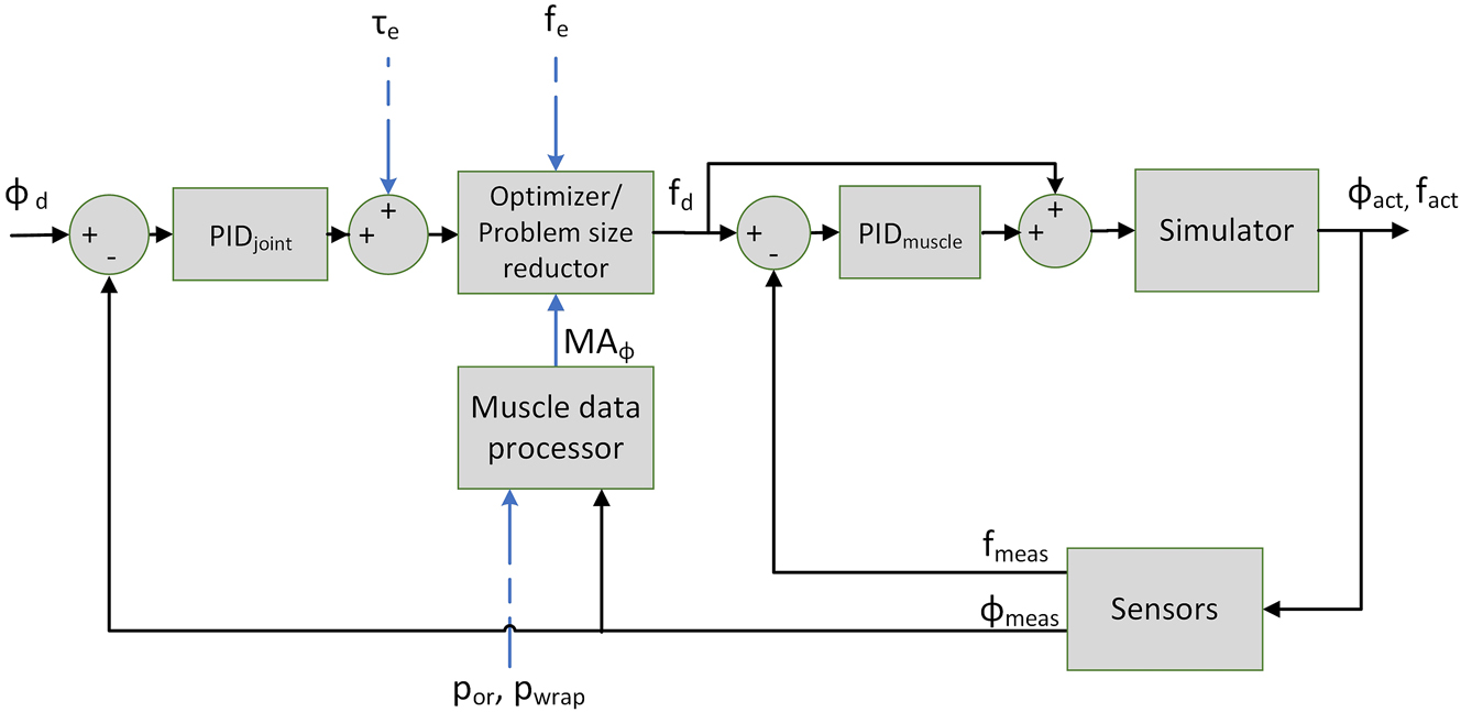
Diagram of the humeral control system. Legend: ϕ d ∈ R 3 are the desired GH joint angles; ϕ act ∈ R 3 are the actual GH joint angles; ϕ meas ∈ R 3 are the measured GH joint angles; τ e ∈ R 3 are the pre-estimated GH torques; f e ∈ R 10 are the pre-estimated muscular forces; f d ∈ R 8 are the desired muscular forces; f act ∈ R 10 are the actual muscular forces; f meas ∈ R 8 are the measured muscular forces; MA ϕ ∈ R 3x10 are the estimated moment arms; p or, p ins ∈ R 3×10 are the pre-estimated origin and insertion points of the muscles.
2.2.1 Pre-estimation of the musculoskeletal parameters
OpenSim 3.3 [19] and the OpenSim API for MATLAB 2021a were used to develop an OpenSim model that replicates the simulator. Using this model, the muscle origin, insertion and wrapping sites (p or, p ins, p wrap), net-torque ( τ e), muscle forces (f e) and their upper limits (f max) are pre-estimated. The p ins are set manually to compensate for the uncertainty of the attaching procedure of the muscles to the humerus. A sphere with a diameter that best fits the articular surface of the humeral head is defined as the muscle-wrapping object around the humeral head. The muscles that span the humeral head are wrapped along this sphere. To prevent sliding of the DELT portions in the OpenSim model, via-points (p via) fixed to the humerus are defined.
Starting from the desired motion profile of each DoF, an inverse dynamics calculation is performed, resulting in the net joint torques ( τ e). To obtain information about the muscle line of action, the origin points (p or) of each muscle at each time step of the motion profile are extracted from the OpenSim model. Additionally, the effective muscle line of action is determined by finding the last point of the muscle line of action (p wrap). This point is either the point where the muscle wraps around an object or, in cases where there is no wrapping, it is simply the muscle’s insertion point p ins. The OpenSim plugin [24] is used to extract this information. Next, muscle optimization is performed to obtain the pre-estimated muscle forces (f e) according to Wu et al. [22]. These muscle forces impose a constraint on the GH joint reaction force (f GH) to limit the ratio of shear to compression force, also known as concavity compression, to the upper limit before subluxation, as established by Lippit et al. [4]. The pre-estimated musculoskeletal parameters are then stored in a table and used by the real-time controller.
2.2.2 Real-time musculoskeletal parameters preparation
The musculoskeletal parameters (from Section 2.2.1) are stored in a table and mapped to the current real-time state by linear interpolation. To accurately account for the position error in the control system, it is essential to consider the effect of an incorrectly assumed humerus position on the moment arm. Therefore, p wrap and p or are rotated according to the actual joint position. Using p wrap and p or, the actual moment arms (MA ϕ ) (3 × 10 matrix) are calculated as follows:
where
2.2.3 Real-time optimizer
A real-time optimizer is used to process the newly determined net joint torques ( τ cor), and actual moment arms (MA ϕ ) to desired muscle forces (f d). The real-time controller optimizes for three weighted conditions to approximate the pre-estimated muscle forces (f e); (i) reducing the activation of muscles forces; (ii) reducing the difference in muscle forces f rt and f e acting on the humeral head; and (iii) reducing the deviation of the GH joint reaction force (f GH) from the line orthogonal to the plane defined by the rim of the glenoid (v glen) (Figure 1d). This line is identical to the Z-axis of the humeral CS system only in the neutral humeral position. A constraint matrix (C) (2 × 10) is defined to describe the relationship between the muscles controlled by the same actuator. Each column (j) of the matrix represents a muscle, and each row (i) represents a constraint. The following equations describe the optimization scheme:
where f
e, f
max and f
rt contain the magnitude of the pre-estimated, maximum, and the real-time obtained muscle forces of all muscle portions (10 × 1 vectors),
τ
cor are the net torques (3 × 1 vector), marm is the mass of the arm, g is the gravity vector, and α, β, and γ are weighting factors of the convex cost function. f
d, (8 × 1) is obtained by adding up the force magnitudes of ISP and TMin (taken from f
rt), adding up the force magnitude of both portions of the SSC (taken from f
rt), and taking all other elements of f
rt. We found the following empirically determined values of the weighting factors to be effective: α = 0.05, β = 0.085, and γ = 1. The
2.2.4 Muscle tear types
Various scenarios were implemented to simulate RC tears. First, the f max of the torn muscles were reduced to 0.5 N (not to 0 N to avoid division by zero errors). In addition, the constraint C was handled differently for each tear type. For healthy and SSP tears, the constraint was applied to both sides. For single-sided partial and complete tear types, no constraint was needed on the torn side and the size of C was reduced by the corresponding row. For tears of both SSC and ISP/TMin, C was omitted completely.
2.3 Evaluation of the simulator’s performance
2.3.1 Repeatability of motion
Before the subsequent test can be performed, a calibration process must be performed. First, the OpenSim origin sites of the muscles must be calibrated. Next, the humerus insertion sites are manually varied to match the physical system. Furthermore, each PID controller of the outer cascade is fine-tuned for each specific test and anthropometry. In addition, the accumulated drift offset of the IMU was corrected prior to each test motion.
Thoracohumeral abduction is often described as combination of scapula rotation and GH abduction, with the humerus performing two parts and the scapula one part of the motion [25]. This ratio between humerus and scapula motion is also referred to as a scapulohumeral rhythm of 2:1. However, it is often assumed that motion below 30° abduction is accomplished only by humerus motion. We demonstrated the repeatability of this relationship by testing three RoMs and scapulohumeral rhythms: 30° and a 0° scapular rotation (30° thoracohumeral abduction), GH abduction of 27° and a 13° scapular rotation (40° thoracohumeral abduction), and a GH abduction of 40° and a 20° scapular rotation (60° thoracohumeral abduction). Ten repetitions of each motion were performed.
2.3.2 Muscle tear types
The simulator performance for the desired motion of 30° GH abduction was evaluated for seven full-thickness RC tear types, and the deviation from the desired motion was analyzed. The tested RC tear types were:
Intact RC (H)
Full-thickness tear of:
SSP
SSCsup
ISP
Combined full-thickness tear of:
SSP & SSCsup
SSP & ISP
SSP & SSCsup & ISP.
During the test, the pulley cable corresponding to the RC tear was disabled completely. To simulate a tear, one of the three portions of the RC (SSCsup, ISP, or SSP) was completely turned off. It is important to note that the SSCsup and the ISP can be turned off by loosening the portion of the cable pulley that connects it with a clamp, whereas the SSP can be turned off by turning off the corresponding EC motor. Three repetitions for each type were performed.
2.3.3 In vivo versus simulator
To compare the performance of the simulator to the in vivo conditions, we used the shoulder implant validation data set provided by OrthoLoad [26]. OrthoLoad is a free, public database of force measurements of various joint implants instrumented with load cells and the corresponding motion capture data (kinematics) of patients with an instrumented implant performing various motion tasks. Our analysis focused on all data sets collected with instrumented shoulder implants for 90° abduction in the frontal plane (0 kg and 2 kg additional weight). The OrthoLoad data set originally included six subjects (n = 3 female, n = 3 male) for the 0 kg and 2 kg additional load cases. All six patients had received a shoulder implant because of osteoarthritis, and their RCs were sufficiently functional to preserve their glenoid. At 27 months after surgery, one male subject reported shoulder and neck pain, and the treating orthopaedic surgeon suspected a possible RC tear [26]. Furthermore, for three subjects, data for the 2 kg additional load were not available, resulting in complete data sets of three subjects. We compared the joint force magnitudes measured by our simulator with those from the OrthoLoad data set. First, we used our simulator to measure joint force magnitudes at 30° abduction for five patient-specific anthropometries (different muscle origin locations) with intact RC. Then, we extracted the magnitude of joint forces at 30° thoracohumeral abduction for each OrthoLoad patient. We used Mann–Whitney U tests to determine if simulator results differed significantly from the OrthoLoad data.
2.3.4 Sensitivity analysis
During the calibration process, it became clear that accurately determining the insertion points p ins significantly affects the motion as they directly affect p wrap. To further illustrate this sensitivity, we performed a forward dynamics simulation of 30° GH abduction using OpenSim 3.3 via the API for MATLAB 2021a. Specifically, we moved the insertion site p ins of the SSC, the combined insertion site of the ISP and the TMin, and the via point p via of the DELTmid either 2 mm posteriorly or 2 mm anteriorly, while leaving the muscle forces at their pre-estimated values.
3 Results
3.1 Repeatability of motion
We observed differences between the desired and the simulated motions for 30°, 40°, and 60° thoracohumeral abduction. The largest errors were observed in GH internal rotation and GH abduction, with maximum errors ranging from 4.7° to 9.2° and maximum standard errors ranging from 0.3° to 7.3°. Errors in scapula rotation and flexion showed were small, with maximum errors ranging from 0.4° to 2.7° and maximum standard errors ranging from 0.3° to 2.3° (Figure 3).
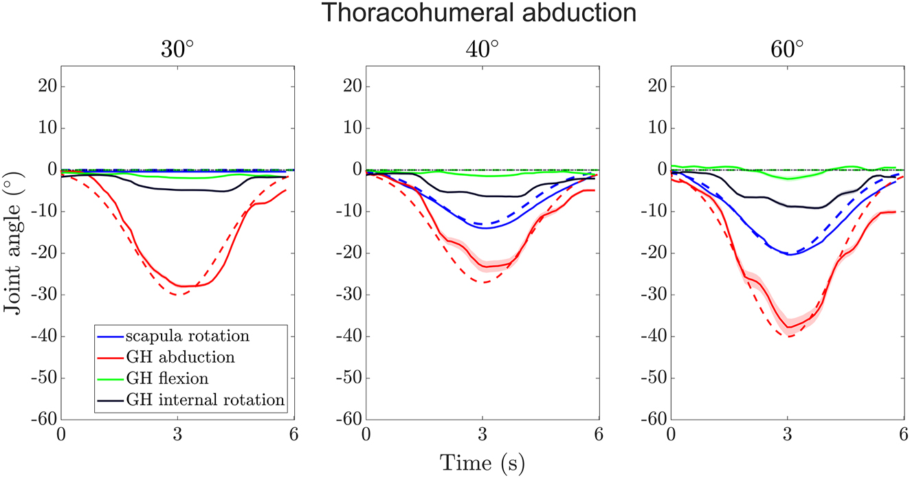
Trajectories of scapula rotation, GH abduction, GH flexion, and GH internal rotation angles over time for the three thoracohumeral abductions (combined scapular rotation and GH abduction) tested. The dotted lines show the desired motion (GH flexion and internal rotation are always zero); the solid lines show the mean measured angles of the motion and the shaded areas their standard errors.
3.2 Tear types
The median errors (deviation to desired motion) for the different tear types were largest in GH internal rotation ranging from 2.9° for SSP & SSCsup & ISP to 4.1° for SSP & ISP (Figure 4). The median errors in GH abduction ranged from 0.7° for SSP & ISP and SSP & SSCsup to 1.4° for ISP and in GH flexion from −0.6° for SSP & SSCsup to 1.0° for SSP & ISP.
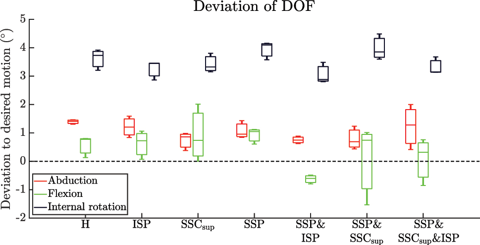
Boxplots of the deviation to the desired motion for each DoF of the humerus (GH abduction, GH flexion, GH internal rotation). Legend: H – intact RC; ISP – RC tear of ISP; SSCsup – RC tear of SSCsup; SSP – RC tear of SSP; SSP & ISP – RC tear of SSP & ISP; SSP & SSCsup – RC tear of SSP & SSCsup; SSP & SSCsup & ISP – RC tear of SSP & SSCsup & ISP.
3.3 In vivo versus simulator
The median joint forces of the simulator and the OrthoLoad subjects at 30° GH abduction with 0 kg additional load were 227.6 N and 206 N, respectively. According to the Mann–Whitney U test, the simulator data did not differ significantly from the OrthoLoad for the 0 kg additional load condition (p = 0.31). The median joint forces of the simulator and the OrthoLoad subjects at 30° GH abduction with 2 kg additional load were 544.7 N and 614.5 N, respectively. According to the Mann–Whitney U test, the simulator data did not differ significantly from the OrthoLoad for the 2 kg additional load condition (p = 0.43) (Figure 5).
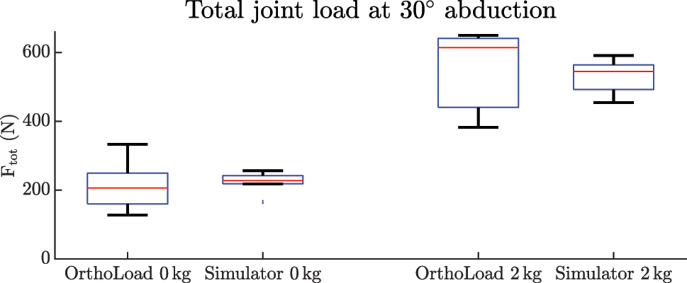
Boxlots of the magnitude of the joint reaction forces of the OrthoLoad data and the simulator experiments without and with 2 kg additional load.
3.4 Sensitivity analysis
The simulation in the unmodified state did not follow the desired curve (Figure 6). The most affected DoF was GH internal rotation. The maximum absolute deviations from the unmodified model were 75.3°, 57.0°, and 87.7° when varying the p via of the DELT, p ins of the ISP & TMin, and p ins of the SSC, respectively. The second most affected DoF was GH flexion. The maximum absolute deviations from the unmodified model were 35.1°, 18.7°, and 39.5° when varying the p via of the DELT, p ins of the ISP & TMin, and p ins of the SSC, respectively. The least affected DoF was GH abduction. The maximum absolute deviations from the unmodified model were 6.0°, 11.4°, and 9.6° when varying the p via of the DELT, p ins of the ISP & TMin, and p ins of the SSC, respectively.
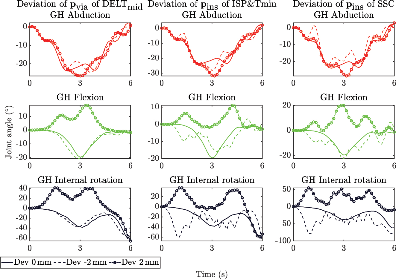
Trajectories of GH abduction (top, red), GH flexion (middle, green), and GH internal rotation (bottom, black) angles over time of the sensitivity analysis for the location of the via point p via of the DELTmid (left), the insertion points p ins of the ISP & TMin (center) and SSC (right) with deviations in X-direction of 0 mm, −2 mm, 2 mm. At all deviated points, GH abduction was least affected, and GH flexion and GH internal rotation were strongly affected at deviations of +2 mm. The deviation of p ins by −2 mm of the ISP & TMin and SSC caused oscillations around the solid line in the deviation.
4 Discussion
4.1 Control strategy
The control strategy seems to perform well overall. The optimization cost function
The structure of the strategy allows easy implementation of a new OpenSim model. Because the OpenSim models for the GH joint are improved constantly, it is necessary to continuously update the model to its latest version [20–22]. In addition, the OpenSim model may be chosen differently depending on the research question. For instance, if an OpenSim model for modeling instability becomes available this could be implemented into a simulator experiment to simulate instability.
In vivo rotation of the scapula is difficult to measure with optical motion capture systems [21] because the scapula slides under the skin. Inman et al. [25] reported a constant scapulohumeral rhythm of 2:1 beyond 30° thoracohumeral abduction or 60° of flexion. Later, McQuade and Smidt [29] showed a nonlinear scapulohumeral rhythm with a dependence on shoulder load. Poppen and Walker [28] also showed that the scapulohumeral rhythm was dependent on shoulder pathology. To improve our simulator, scapula kinematics derived from image-based methods, such as dynamic biplanar or uniplanar fluoroscopy, should be implemented to determine pathology-based scapular motion.
4.2 Repeatability of motion
The simulator can accurately reproduce joint motion, but the precise placement of the insertion sites is critical for achieving accurate results. Because our assumed insertion sites may deviate from the true insertion sites and using the controller our simulator produced repeatable results, we conclude that the controller can compensate for these inaccuracies in the location of the insertion points. However, it was difficult to maintain GH internal rotation in the natural position, especially at higher abduction angles. The GH flexion angle could be kept within a reasonable range. To the best of our knowledge, there is only one study that has shown the performance of their simulator [12]. Therefore, there is currently no benchmark for evaluating the accuracy of state-of-the-art simulators. The internal rotation DoF yielded the largest error, which is consistent with the results of the sensitivity analysis. For the GH abduction DoF, the adduction phase resulted in the largest errors. In addition, the larger the RoM, the greater the susceptibility of the motion to errors. This could be due to the approximation of the OpenSim model. In contrast to the simulator, the DELT via points in the model are fixed to the humerus. Therefore, some anteroposterior sliding still occurs in the simulator despite the Kirschner wires limiting anteroposterior sliding. In addition, the DELT portions slide over the humeral head towards the cable pulleys. Therefore, an improvement in estimating the lever arm of the model could significantly impact the performance of the simulator.
4.3 Tear types
The simulator accurately reproduced the motion of various RC tears and deviated only slightly from the intact RC. As with the intact RC, in the RC tears, internal rotation had the greatest deviation from the desired motion, while the errors of the achieved GH abduction and GH flexion angles were much smaller and very close to those of the intact RC. These results clearly demonstrate that our simulator is suitable for investigating the biomechanics of untreated RC tears, such as joint stability and joint translation. It is worth noting that our simulator is limited to mimicking full-thickness RC tears. Partial-thickness tears could potentially be simulated to some extent by reducing the maximum muscle force of the respective affected muscle.
4.4 In vivo versus simulator
The simulator shows promising results in reproducing the magnitude of the joint reaction forces of the OrthoLoad data [26] without significant differences between the simulator and the in vivo data set. However, it is important to note that the motion of the two data sets is not identical. The OrthoLoad motion task was abduction in the frontal plane and went beyond 30° and up to 90°. In addition, the abduction velocity varied between the subjects included in the OrthoLoad data set. The simulator models the muscles with simple cable actuation, whereas the muscles in vivo have a much larger volume that also alters their apparent stiffness during contraction. The simulator partially addresses this limitation by the implementation of different portions of the same muscles. This approach helps to better estimate the contact pressure of the muscle on the humerus and, thus the joint compliance. It is worth noting that the simulator does not currently simulate four of the 11 muscles, namely the coracobrachialis, biceps, triceps, and teres major. In addition, the biceps has multiple origin sites on the scapula that must be implemented separately, but previous studies have shown that the long head of the biceps does not play a significant role in GH motion [30].
4.5 Sensitivity analysis
The sensitivity analysis showed that the forward dynamics simulation could not reproduce the optimization of Wu et al. [22]. Because the optimization of Wu et al. is a static optimization — as it neglects all dynamic behavior during the actual optimization — errors can accumulate during the integration of the system equations, making it more sensitive to uncertainties. While the optimization in our simulator also neglects the dynamic behavior, the resulting errors are taken into account by the PID controller for the joint position and kinematic measurements that constantly update the optimizer. It has also been shown that the precise placement of the insertion sites is of paramount importance and has a strong effect on the motion. In particular, variations in insertion sites have a strong effect on GH internal rotation. Therefore, precise calibration of the insertion sites is necessary to ensure accurate results. Alternatively, one could constrain the DoF of internal rotation, but this approach could compromise the accuracy of the muscle activity and joint forces.
5 Conclusions
The sensitivity analysis has shown that accurate placement of insertion sites is critical to achieve accurate results in GH joint motion. Although the simulator can accurately reproduce GH joint motion, errors occur in the internal rotation and GH abduction DoF during the adduction phase. Overall, the control strategy performs well and appears to be suitable for studying the physiological principles of GH dynamics in more detail, both in healthy shoulders and in shoulders with RC tears. The simulator shows promising results in reproducing in vivo joint reaction forces, but limitations in muscle modeling and replicating scapula rotation based on physiological measurements require attention. In addition, further research is required to address the remaining issues leading to internal rotation of the humerus. These efforts are essential to achieve highly reliable simulations over the full range of humeral abduction angles up to 30°.
Funding source: Swiss National Science Funds (SNSF)
Award Identifier / Grant number: 320030_189082
About the authors

Jeremy Genter is currently pursuing his PhD at the University of Basel and Zurich University of Applied Sciences, under the guidance of Prof. Mündermann and Prof. Baumgartner. He is closely collaborating with Prof. Rauter in the Department of Biomedical Engineering at the University of Basel.
Georg Rauter is Associate Prof. for Surgical Robotics at the BIROMED-Lab. His background is Mechanical Engineering (TU-Graz) and Mathematical and Mechanical Modeling (MATMECA, Bordeaux). In 2014 he received his PhD in robotics from ETH Zurich.
Prof. Müller is the current Head of the Department of Orthopaedics and Traumatology. He has expertise in the diagnosis and therapy of musculoskeletal disorders and orthopaedic surgery. He received his medical training at the University of Basel, Basel, Switzerland.

Prof. Mündermann is the Research Director of the Functional Biomechanics Research Group at the Department of Orthopaedics and Traumatology, University Hospital Basel, Basel, Switzerland. She received her PhD in Medical Sciences from the University of Calgary, Canada.

Prof. Baumgartner is Professor in Biomechanical Engineering and is the current head of the group of Biomechanics at the IMES Institute of Mechanical Systems. He received his PhD in 2009 in the field of Biomechanical Engineering from ETH, Zürich, Switzerland.
-
Author contributions: All the authors have accepted responsibility for the entire content of this submitted manuscript and approved submission.
-
Research funding: This project is funded by the Swiss National Science Funds (SNSF grant 320030_189082). The funders had no role in the study design, data collection, analysis, decision to publish, or preparation of the manuscript.
-
Conflict of interest statement: The authors declare no conflicts of interest regarding this article.
References
[1] H. E. Veeger and F. C. van der Helm, “Shoulder function: the perfect compromise between mobility and stability,” J. Biomech., vol. 40, no. 10, pp. 2119–2129, 2007. https://doi.org/10.1016/j.jbiomech.2006.10.016.Search in Google Scholar PubMed
[2] R. Lugo, P. Kung, and C. B. Ma, “Shoulder biomechanics,” Eur. J. Radiol., vol. 68, no. 1, pp. 16–24, 2008. https://doi.org/10.1016/j.ejrad.2008.02.051.Search in Google Scholar PubMed
[3] J. Lewis, “Rotator cuff related shoulder pain: assessment, management and uncertainties,” Man. Ther., vol. 23, pp. 57–68, 2016. https://doi.org/10.1016/j.math.2016.03.009.Search in Google Scholar PubMed
[4] S. Lippitt and F. Matsen, “Mechanisms of glenohumeral joint stability,” Clin. Orthop. Relat. Res., vol. 291, no. 291, pp. 20–28, 1993. https://doi.org/10.1097/00003086-199306000-00004.Search in Google Scholar
[5] F. Billuart, L. Devun, W. Skalli, D. Mitton, and O. Gagey, “Role of deltoid and passives elements in stabilization during abduction motion (0 degrees-40 degrees): an ex vivo study,” Surg. Radiol. Anat., vol. 30, no. 7, pp. 563–568, 2008. https://doi.org/10.1007/s00276-008-0374-x.Search in Google Scholar PubMed
[6] K. M. Clabbers, J. D. Kelly, D. Bader, et al.., “Effect of posterior capsule tightness on glenohumeral translation in the late-cocking phase of pitching,” J. Sport Rehabil., vol. 16, no. 1, pp. 41–49, 2007. https://doi.org/10.1123/jsr.16.1.41.Search in Google Scholar PubMed
[7] A. E. Kedgley, G. A. Mackenzie, L. M. Ferreira, et al.., “The effect of muscle loading on the kinematics of in vitro glenohumeral abduction,” J. Biomech., vol. 40, no. 13, pp. 2953–2960, 2007. https://doi.org/10.1016/j.jbiomech.2007.02.008.Search in Google Scholar PubMed
[8] D. C. Ackland, S. Roshan-Zamir, M. Richardson, and M. G. Pandy, “Muscle and joint-contact loading at the glenohumeral joint after reverse total shoulder arthroplasty,” J. Orthop. Res., vol. 29, no. 12, pp. 1850–1858, 2011. https://doi.org/10.1002/jor.21437.Search in Google Scholar PubMed
[9] P. Williamson, A. Mohamadi, A. J. Ramappa, J. P. DeAngelis, and A. Nazarian, “Shoulder biomechanics of rc repair and instability: a systematic review of cadaveric methodology,” J. Biomech., vol. 82, pp. 280–290, 2019. https://doi.org/10.1016/j.jbiomech.2018.11.005.Search in Google Scholar PubMed
[10] D. Baumgartner, D. Tomas, L. Gossweiler, W. Siegl, G. Osterhoff, and B. Heinlein, “Towards the development of a novel experimental shoulder simulator with rotating scapula and individually controlled muscle forces simulating the rotator cuff,” Med. Biol. Eng. Comput., vol. 52, no. 3, pp. 293–299, 2014. https://doi.org/10.1007/s11517-013-1120-z.Search in Google Scholar PubMed
[11] M. Apreleva, I. M. T. Parsons, J. J. Warner, F. H. Fu, and S. L. Woo, “Experimental investigation of reaction forces at the glenohumeral joint during active abduction,” J. Shoulder Elbow Surg., vol. 9, no. 5, pp. 409–417, 2000. https://doi.org/10.1067/mse.2000.106321.Search in Google Scholar PubMed
[12] J. W. Giles, L. M. Ferreira, G. S. Athwal, and J. A. Johnson, “Development and performance evaluation of a multi-pid muscle loading driven in vitro active-motion shoulder simulator and application to assessing reverse total shoulder arthroplasty,” J. Biomech. Eng., vol. 136, no. 12, p. 121007, 2014. https://doi.org/10.1115/1.4028820.Search in Google Scholar PubMed
[13] M. Kronberg, G. Németh, and L. A. Broström, “Muscle activity and coordination in the normal shoulder. An electromyographic study,” Clin. Orthop. Relat. Res., vol. 257, pp. 76–85, 1990. https://doi.org/10.1097/00003086-199008000-00016.Search in Google Scholar
[14] F. Dyrna, N. S. Kumar, E. Obopilwe, et al.., “Relationship between deltoid and rotator cuff muscles during dynamic shoulder abduction: a biomechanical study of rotator cuff tear progression,” Am. J. Sports Med., vol. 46, no. 8, pp. 1919–1926, 2018. https://doi.org/10.1177/0363546518768276.Search in Google Scholar PubMed
[15] L. V. Gulotta, D. Choi, P. Marinello, et al.., “Humeral component retroversion in reverse total shoulder arthroplasty: a biomechanical study,” J. Shoulder Elbow Surg., vol. 21, no. 9, pp. 1121–1127, 2012. https://doi.org/10.1016/j.jse.2011.07.027.Search in Google Scholar PubMed
[16] L. V. Gulotta, D. Choi, P. Marinello, et al.., “Anterior deltoid deficiency in reverse total shoulder replacement: a biomechanical study with cadavers,” J. Bone Jt. Surg. Br., vol. 94, no. 12, pp. 1666–1669, 2012. https://doi.org/10.1302/0301-620x.94b12.29116.Search in Google Scholar
[17] M. L. Hansen, J. C. Otis, J. S. Johnson, F. A. Cordasco, E. V. Craig, and R. F. Warren, “Biomechanics of massive rotator cuff tears: implications for treatment,” J. Bone Jt. Surg. Am., vol. 90, no. 2, pp. 316–325, 2008. https://doi.org/10.2106/jbjs.f.00880.Search in Google Scholar
[18] J. Scalise, A. Jaczynski, and M. Jacofsky, “The effect of glenosphere diameter and eccentricity on deltoid power in reverse shoulder arthroplasty,” Bone Joint J, vol. 98-b, no. 2, pp. 218–223, 2016. https://doi.org/10.1302/0301-620x.98b2.35912.Search in Google Scholar PubMed
[19] S. L. Delp, F. C. Anderson, A. S. Arnold, et al.., “Opensim: open-source software to create and analyze dynamic simulations of movement,” IEEE Trans. Biomed. Eng., vol. 54, no. 11, pp. 1940–1950, 2007. https://doi.org/10.1109/tbme.2007.901024.Search in Google Scholar PubMed
[20] A. A. Nikooyan, H. E. Veeger, P. Westerhoff, F. Graichen, G. Bergmann, and F. C. van der Helm, “Validation of the delft shoulder and elbow model using in-vivo glenohumeral joint contact forces,” J. Biomech., vol. 43, no. 15, pp. 3007–3014, 2010. https://doi.org/10.1016/j.jbiomech.2010.06.015.Search in Google Scholar PubMed
[21] A. Seth, R. Matias, A. P. Veloso, and S. L. Delp, “A biomechanical model of the scapulothoracic joint to accurately capture scapular kinematics during shoulder movements,” PLoS One, vol. 11, no. 1, p. e0141028, 2016. https://doi.org/10.1371/journal.pone.0141028.Search in Google Scholar PubMed PubMed Central
[22] W. Wu, P. V. S. Lee, A. L. Bryant, M. Galea, and D. C. Ackland, “Subject-specific musculoskeletal modeling in the evaluation of shoulder muscle and joint function,” J. Biomech., vol. 49, no. 15, pp. 3626–3634, 2016. https://doi.org/10.1016/j.jbiomech.2016.09.025.Search in Google Scholar PubMed
[23] S. Richter, “Computational complexity certification of gradient methods for real-time model predictive control,” PhD thesis, ETH Zurich, Zurich, Switzerland, 2012.Search in Google Scholar
[24] R. J. van Arkel, L. Modenese, A. Phillips, and J. R. Jeffers, “Hip abduction can prevent posterior edge loading of hip replacements,” J. Orthop. Res., vol. 31, pp. 1172–1179, 2013. https://doi.org/10.1002/jor.22364.Search in Google Scholar PubMed PubMed Central
[25] V. T. Inman, J. B. Saunders, and L. C. Abbott, “Observations of the function of the shoulder joint. 1944,” Clin. Orthop. Relat. Res., vol. 330, no. 330, pp. 3–12, 1996. https://doi.org/10.1097/00003086-199609000-00002.Search in Google Scholar PubMed
[26] G. Bergmann, F. Graichen, A. Bender, et al.., “In vivo gleno-humeral joint loads during forward flexion and abduction,” J. Biomech., vol. 44, no. 8, pp. 1543–1552, 2011. https://doi.org/10.1016/j.jbiomech.2011.02.142.Search in Google Scholar PubMed
[27] P. M. Ludewig and T. M. Cook, “Translations of the humerus in persons with shoulder impingement symptoms,” J. Orthop. Sports Phys. Ther., vol. 32, no. 6, pp. 248–259, 2002. https://doi.org/10.2519/jospt.2002.32.6.248.Search in Google Scholar PubMed
[28] N. K. Poppen and P. S. Walker, “Normal and abnormal motion of the shoulder,” J. Bone Jt. Surg. Am., vol. 58, no. 2, pp. 195–201, 1976. https://doi.org/10.2106/00004623-197658020-00006.Search in Google Scholar
[29] K. J. McQuade and G. L. Smidt, “Dynamic scapulohumeral rhythm: the effects of external resistance during elevation of the arm in the scapular plane,” J. Orthop. Sports Phys. Ther., vol. 27, no. 2, pp. 125–133, 1998. https://doi.org/10.2519/jospt.1998.27.2.125.Search in Google Scholar PubMed
[30] J. E. Giphart, F. Elser, C. B. Dewing, M. R. Torry, and P. J. Millett, “The long head of the biceps tendon has minimal effect on in vivo glenohumeral kinematics: a biplane fluoroscopy study,” Am. J. Sports Med., vol. 40, no. 1, pp. 202–212, 2012. https://doi.org/10.1177/0363546511423629.Search in Google Scholar PubMed
© 2023 the author(s), published by De Gruyter, Berlin/Boston
This work is licensed under the Creative Commons Attribution 4.0 International License.
Articles in the same Issue
- Frontmatter
- Editorial
- Special issue: Minimal-invasive robotics
- Methods
- Musculoskeletal model-based control strategy of an over-actuated glenohumeral simulator to assess joint biomechanics
- Qualitative and quantitative assessment of admittance controllers for hand-guiding surgical robots
- Continuum robot actuation by a single motor per antagonistic tendon pair: workspace and repeatability analysis
- Development of an AI-driven system for neurosurgery with a usability study: a step towards minimal invasive robotics
- Compact flexible actuator based on a shape memory alloy for shaping surgical instruments
- Shape-sensing by self-sensing of shape memory alloy instruments for minimal invasive surgery
- Minimally invasive in situ bioprinting using tube-based material transfer
- Applications
- Deep learning assisted intraoperative instrument cleaning station for robotic scrub nurse systems