Qualitative and quantitative assessment of admittance controllers for hand-guiding surgical robots
-
Murali Karnam
 ,
Philippe C. Cattin
,
Philippe C. Cattin

Abstract
When using redundant medical robots for hand-guiding heavy endoscopic tools, admittance control allows a completely defined tool and robot null space motion control. Although not a novel concept, comparative studies that help to design and implement admittance control are missing. In a user study, we compared four admittance controllers: one zero-torque controller that used measured joint torques and three others differently mapping forces/torques measured at the handle to tool tip velocity. We found that two of the four controllers (Dynamic Mass and Integrated Mass) outperformed the others.
Zusammenfassung
Zur Handführung von schweren endoskopischen Werkzeugen mit redundanten Medizinrobotern bieten die Admittanzregler eine vollständig definierte Bewegungssteuerung. Obwohl dies kein neues Konzept ist, fehlen Vergleichsstudien zur Entwicklung und Implementierung der Admittanzregler. In einer Studie haben wir vier Admittanzregler verglichen: einen Nullmomentregler, basierend auf gemessenen Gelenksmomenten, und drei weitere, die am Griff gemessene Kräfte/Drehmomente verschieden auf Sollgeschwindigkeiten abbilden. Zwei der vier Regler (dynamische Masse und integrierte Masse) übertrafen die anderen.
1 Introduction
Many surgical tasks require gross tool motion, where the tools are moved and positioned with a macro-scale (∼1 cm) accuracy; for example, to insert tools into trocars, to exchange tools, to clean the tools. There also exist procedures that mostly require such macro-motion, for example, to move an ultrasound scanner mounted on a robot [1], and for dental assistance [2]. Traditional surgical robots, such as the Da Vinci Surgical System (Intuitive Surgical, USA), incorporate back-steerable passive mechanisms as tool holders and allow surgeons to hand-guide the tools. Such passive robots can limit a surgeons’ ability to make easy yet accurate gross tool movements, especially for heavy and bulky tools.
As an alternative, newer specific and general-purpose macro-robots use active serial robots and controllers that allow surgeons to hand-guide tools. For example, the MAKO Robot-Arms (Stryker, USA) performs knee surgeries that allow hand-guiding and constrain a surgeons’ movements along pre-planned surgical paths to ensure safety and accuracy. Beyond such intervention-specific robots, there are general-purpose medical macro-robots on the market that allow safe physical human-robot-interaction (pHRI), for example, the KUKA LBR iiwa Med (KUKA AG, Augsburg, Germany). Different tools can be mounted on such robots for medical applications; for example, in Laserosteotomy [3], breast biopsy using ultrasound scanning [1], and radiation therapy [4]. Other macro-robots that are safe for pHRI have also been used in research for surgical applications; for example, the Panda (Franka Emika, Germany) for dental assistance [2] and middle ear surgery [5], or the UR 5 (Universal Robots, Denmark) for needle insertion [6]. However, most of these macro-robots are kinematically redundant for the task – they position the tools during surgery as required and at the same time follow additional task(s), such as constraining the tool to a remote center of motion (RCM) [7] or avoid obstacles [8]. While these macro-robots allow surgeons to move tools, hand-guiding such redundant robots easily is challenging and often requires two-handed operation such as when moving a zero torque controlled KUKA LBR iiwa [9]. We hypothesize that a surgeons’ effort can be reduced with a one-handed interface to hand-guide redundant robots.
We found three main control paradigms for pHRI of macro-robots – zero torque control (ZTC) [9], impedance control [10], and admittance control [11]. In ZTC, the robot is gravity balanced with a feed-forward model, and the user-input is measured at the robot joints and compensated for having a net zero torque. ZTC requires suitable mass models for the robot and tools. Hand-guiding kinematically redundant robots is more challenging for the user, because it may require two-handed interaction to achieve the robot motion. In impedance control, the robot measures movement, and reacts with a force/torque. Thereby, impedance control can potentially be used to control a reference movement with low gains and react to user input, which may help to make robots safe and reactive in many automation tasks. We considered impedance control less suitable for hand guidance of surgery, where the desired positions would be defined while hand-guiding and must be maintained accurately even in the presence of interaction forces between tools and patient anatomy. In admittance control, the user input force/torque is measured, and a robot movement is commanded (Figure 1). It allows surgeons to guide the robot precisely and apply forces to patient anatomy by tools needed for the surgery. Furthermore, admittance control with a cascaded control scheme allows choosing inverse kinematics solutions for redundant robots avoiding joint limitations as well as adding supportive features such as speed limitations, virtual fixtures, or tremor filtering similar to tele-manipulation, thereby making it a promising choice for hand guidance in surgery.

A hand-guided robot operated by a surgeon. The surgeon’s input
Admittance controller design typically involves a trade-off between compliance and stability. Compliance is the ratio of the output robot velocity to user input wrench; the more compliant the robot, the less the reflected inertia to the user, and thus easier to hand-guide. As the compliance is increased, the robot’s stable input region reduces. While there have been theoretical suggestions to increase compliance while maintaining stability [12], two questions in admittance controller design remain – (1) where should the user input (wrench) be measured, and (2) which admittance control map (a function that converts the measured wrench to robot joint velocity) should be used?
In the literature, researchers used different options for these two choices. A common choice for measuring user input is at the tool in task space with a force/torque sensor. Nevertheless, most robots typically have maps that only rely on joint torque sensors [9, 13], which is cheaper because an additional force/torque sensor is not needed near the tool. A simple filter [14], a first-order mass model [15], a second-order mass-damper model [16–18], a second-order mass-spring-damper model [19] or a proportional-derivative model [5] have been used in literature as admittance control maps to hand-guide surgical robots. Beyond robots for surgery, admittance control maps have also been used in industrial robotics. For example, a filter with a second-order mass damper has been used to allow users to drill with assistance using a robot [20]. Similarly, a second-order mass spring damper has been used to move a robot constrained to move on a reference trajectory [21]. While many different maps are used in literature to ascertain their feasibility, only a few user studies have quantitatively assessed the map choice in hand-guiding robots. For example, a user study with five participants has been conducted to compare robotic and laparoscopic needle stitching [18]. Hand guidance with different adaptive gains has been compared in a 3-D path-tracing task with 20 participants [15]. In these studies, researchers have implemented and compared the admittance control to be useful or not. Nevertheless, which admittance control map is intuitive or most suitable to the user for hand-guiding a robot remains unanswered.
Surgeries typically demand time and effort from the surgeons. In this work, we aim to develop an admittance controller for a robot that allows surgeons to move the robot precisely, intuitively using one hand and with low effort. To answer the two questions on the admittance controller design, we implemented different admittance control maps on a single robot and assessed which map is more intuitive to control in a user study. We also compared the maps that measured the user input at the tool with the ZTC that measured the user input at the joints as a baseline.
2 Methods
2.1 Experimental setup
The setup consisted of a KUKA LBR iiwa robot in a mock-up surgery environment (as shown in Figure 2). The robot had a custom-developed handle as an end-effector. The handle included a 6 degrees-of-freedom (DoF) force/torque (F/T) sensor (Mini 45, ATI Automation, USA) to measure the user-applied wrench (forces and torques). A mock-up endoscope was attached to the robot concentric to the handle. The mock-up endoscope and the handle with the F/T sensor were structurally separated; thereby, only the user-applied wrench on the handle was measured. The interaction wrench between the endoscope and the environment (patient) was transmitted to the robot and cannot be felt at the handle. The measured wrench at the handle was used as input to an admittance controller that allowed a user to hand-guide the robot.
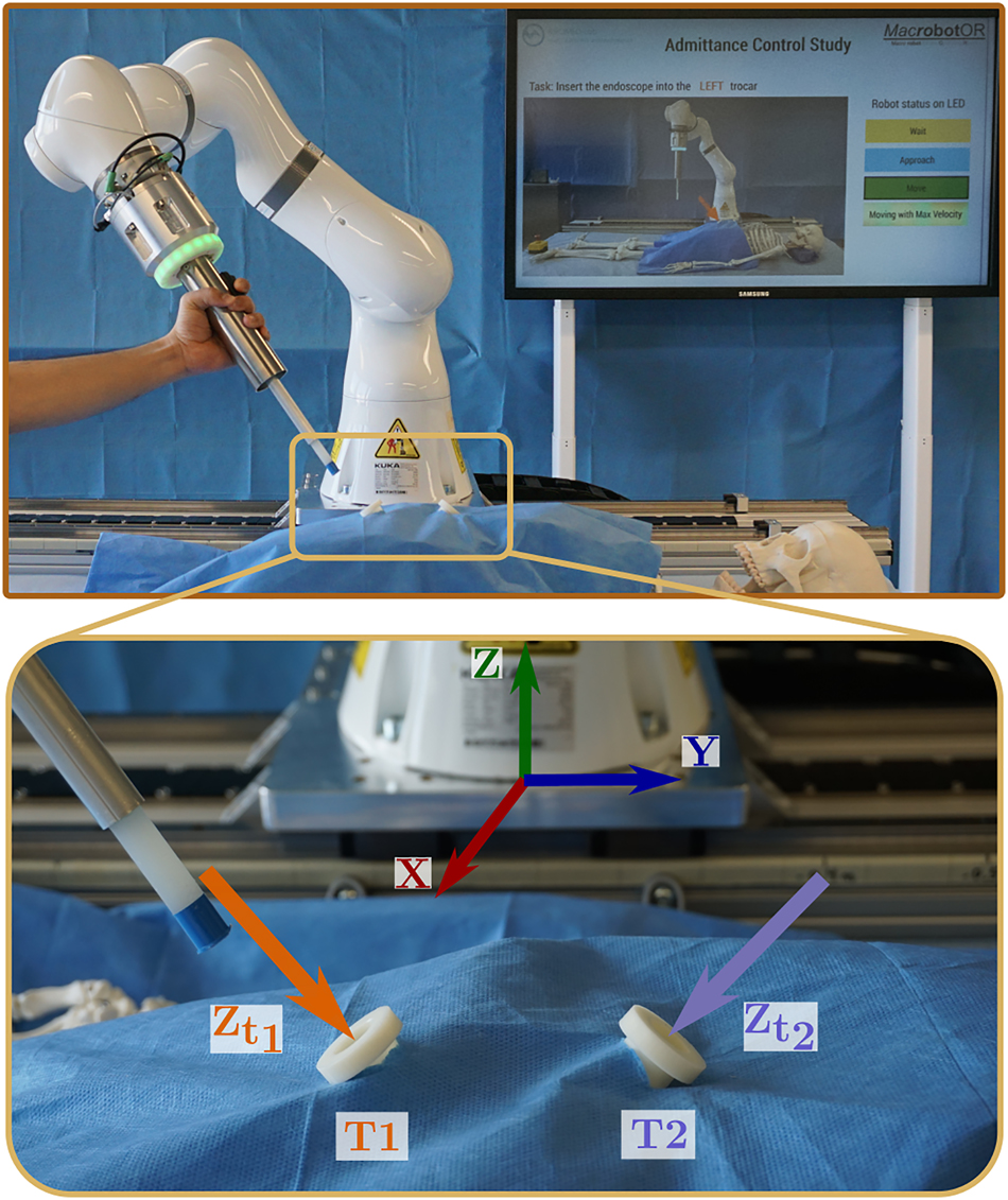
Experimental apparatus (top) consisting of KUKA LBR iiwa robot (KUKA AG, Augsburg, Germany) with a custom-developed handle with integrated force/torque sensor (mini45, ATI industrial automation, USA) and LED status ring, a concentric dummy endoscope as end-effector, and a TV screen in the back guiding participants through the protocol. Zoomed view (bottom) of the two target trocars with overlaid trocar Z-axis and robot base coordinate frame.
The robot was fixed to an operating table with a mock-up patient (a skeleton dummy). Two trocars were rigidly fixed symmetrically to the robot origin near the abdomen region. The trocars were positioned [0.55 m, ±0.05 m, 0.1 m] away from the robot base. The trocar T1 was rotated by [−15°, 220°], and trocar T2 by [15°, −220°] about the fixed global X and Z axes respectively. A workspace visualization tool previously developed [22] was used to make sure that there was sufficient rotational workspace for the robot near the trocar.
The user operated the robot only after the instructor pressed the enabling switch on the hand-held KUKA SmartPad. The handle had an integrated 3-position dead man’s switch that allowed the user to start the hand-guiding motion. There was a speed limit of 0.2 m/s (lower than 0.25 m/s as per ISO 10218-1 for safe human-robot interaction) for any part of the robot. A safe torque limit of 30 Nm at any joint was imposed, and a violation made the robot go to a safety stop. The motion could be resumed after the instructor removed the robot from the safety violation. The workspace was restricted so that all parts of the robot were above the table. The participants were instructed to hand-guide the robot with a power grasp on the handle, and to use the index finger for the enabling switch. The status of the robot was displayed with a LED ring on the handle with three states – not ready (yellow), ready (blue), hand guidance enabled (green). During hand-guiding motion, the LED ring additionally showed linearly interpolated yellow on every second LED from no brightness to maximum brightness corresponding to the ratio of the robot speed and the maximum allowed speed.
2.2 Control
The robot was operated in one of the two control modes: (I) KUKA hand guidance mode that was pre-programmed by the manufacturer for users to hand-guide the robot, and (II) external position control mode using the Fast Robot Interface (FRI) to command the desired joint positions as calculated by our admittance controller programmed on a real-time controller architecture [23] at 1 kHz. In a preliminary analysis, it was found that the joint torque signal from the robot had a significant delay (≈7.5 ms) when the robot was in external control mode. Thus, only the wrench measured by the handle was used with the external control mode.
Users hand-guided the robot with each of the four admittance control maps that are described in detail below. All the maps had a few constant parameters (c *). These parameters of each map were manually tuned (see Table 1 for final values) with the objective of reducing the force and torque required to move the robot as long as the robot motion was stable (without oscillations) for safe user interaction.
Tuned parameters for all the admittance control maps.
| Map |
|
c ω | c d | c t |
|---|---|---|---|---|
| KUKA hand guidance | – | – | – | – |
| Filter | [0.20, 0.20, 0.20, 1.40, 1.40, 10] | 2 | 0.3 | – |
| Integrated mass | [0.13, 0.13, 0.13, 0.77, 0.77, 3.3] | – | 3.0 | 3000 |
| Dynamic mass | [0.13, 0.13, 0.13, 0.77, 0.77, 3.3] | – | 3.0 | – |
2.2.1 KUKA hand guidance
It was designed by the manufacturer as a zero torque controller [9] and implemented directly on the KUKA controller using the KUKA hand guidance control mode (I). In this map, the user-applied wrench was measured by the joint torque sensors of the robot. Users were allowed to use two hands (dominant hand on the handle, and the other on the robot) because the robot could collapse as null space motion was uncontrolled. Therefore, this map was added for a baseline comparison with the other maps, even though it was not one-handed.
2.2.2 Filter
In this admittance control map, the user-applied wrench
where, Tip
T
FT is the fixed transformation matrix from the F/T sensor pose to the endoscope tip. Henceforth the superscript
The measured wrench was filtered and scaled to calculate the desired task space velocity (
where, k was the discretized time-step,
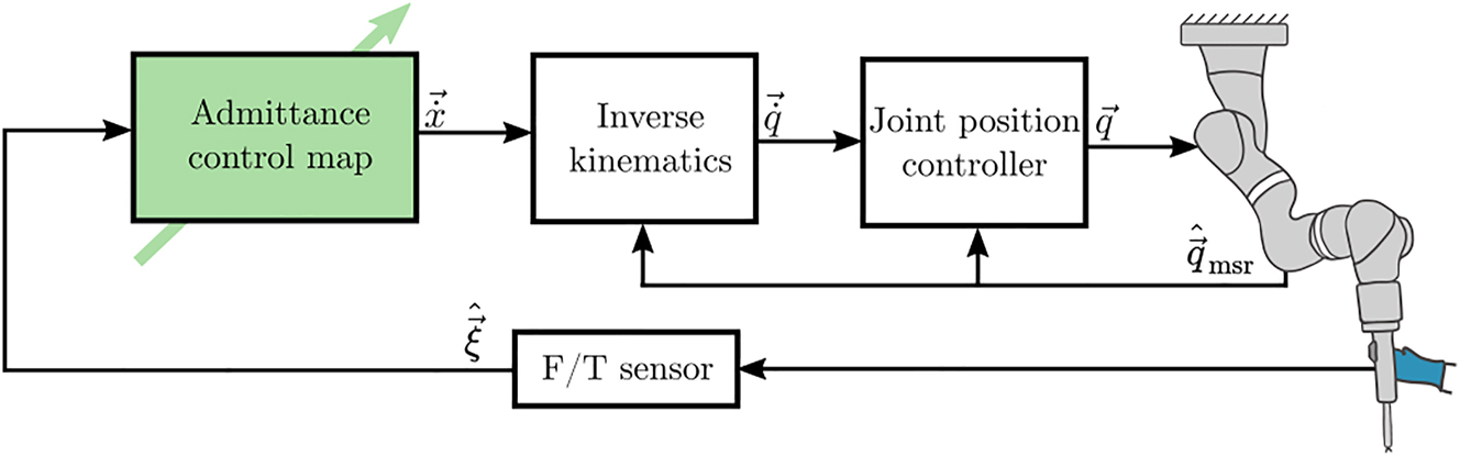
Controller architecture for the three implemented admittance control maps using external position control mode. The user-applied wrench was measured by the F/T sensor in the handle, which was used to calculate the desired task space velocity for the robot. Standard inverse kinematics using pseudo-inverse was used to calculate desired joint velocities that were integrated with a fixed time-step to calculate joint position commands.
2.2.3 Integrated mass
In this map, the measured wrench was assumed to be acting on a pseudo-rigid body with a diagonal mass matrix. The resulting instantaneous acceleration of the rigid body was damped and multiplied with the real-time step to find an instantaneous velocity. A weighted cumulative average of the instantaneous and previous velocity was taken to calculate the desired velocity of the endoscope tip as:
where, c
t
was a constant representing the number of samples for the cumulative average, and
2.2.4 Dynamic mass
This map was similar to the Integrated mass, and the measured wrench acted on a pseudo-rigid body. The resulting acceleration was damped and integrated with respect to time using explicit Euler formulation to calculate the desired velocity as:
where all the parameters are the same as in Filter, except for c t (see Table 1 for tuned final values).
2.3 Study design
2.3.1 Participants
Thirty-four healthy volunteers participated in the study. Due to a technical error in data recording with two participants, they were excluded completely, and the data of 32 participants (18M–14F of 20 years–56 years old, with a mean age of 32.3 years) was used for analysis. All participants did not have any experience with controlling surgical robots hands-on and did not have any upper arm injuries. Participants with a medical background (N = 4) had experience in laparoscopic/arthroscopic surgical procedures. The remaining participants (N = 28) were researchers from the University of Basel. The study was conducted according to the declaration of Helsinki and the law of Switzerland. A clarification of responsibility (Req-2021-01148) was obtained from the Ethics Commission of Northwest and Central Switzerland. A signed informed consent was obtained from all participants.
To account for the learning effect across the maps, the order for the conditions were randomized with randomly generated 4th-order Latin squares. There were eight Latin squares in total for the 32 participants. Due to an experimental error, the order of the conditions was incorrect for one out of the 32 evaluated participants; this one slightly unbalanced Latin square out of eight was not considered critical to the evaluation and results.
2.3.2 Experimental protocol
The participants performed eight robot movements with each of the four admittance control maps sequentially (Figure 4).
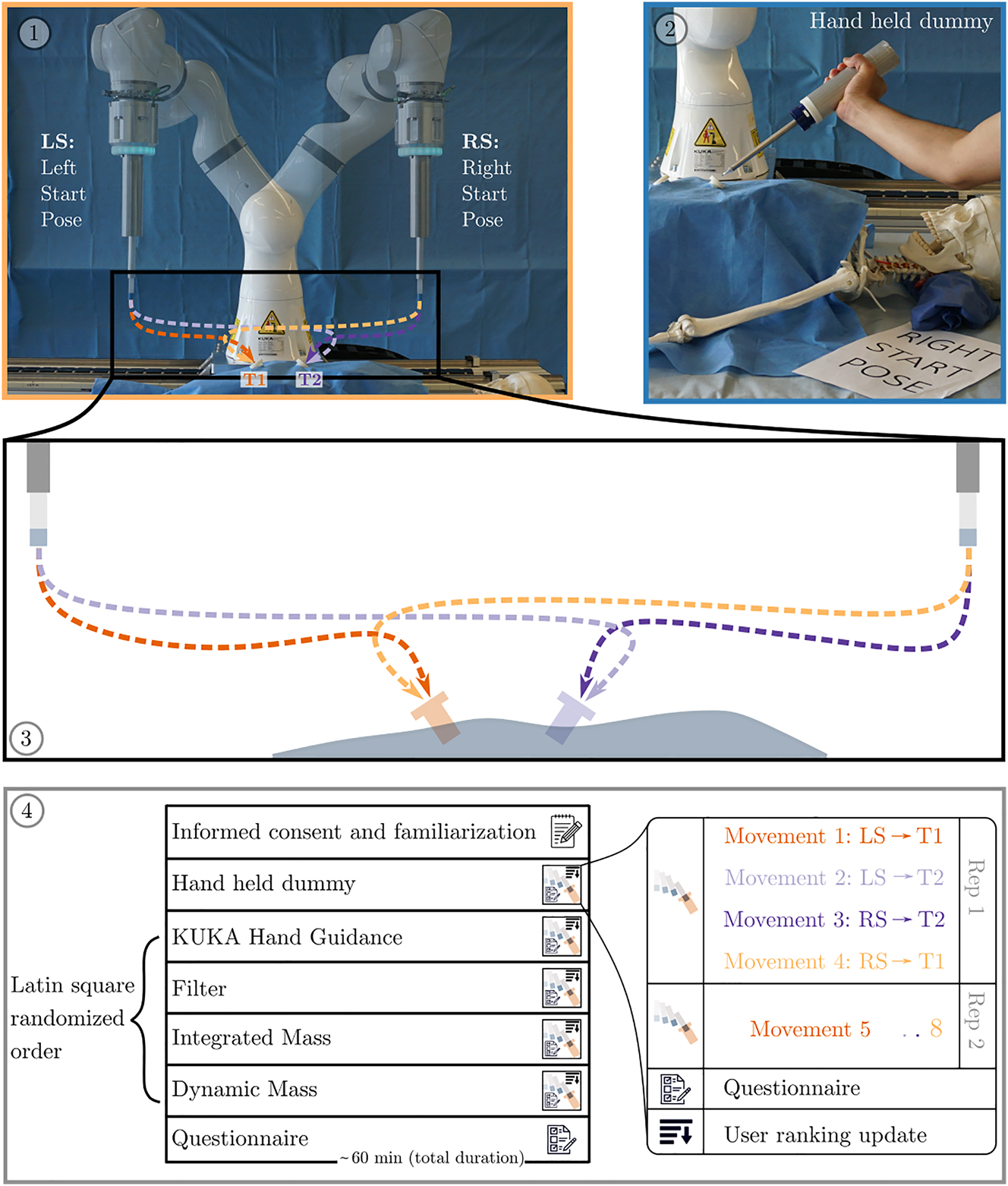
Study protocol for the participants had three main parts: informed consent and familiarization, performing the movements and answering questionnaires. ①: The setup of the study with the two robot start poses (LS and RS) and target trocars (T1 and T2). ②: To get acquainted with the procedure, the participants first performed the movements with a dummy hand-held endoscope. ③: With each of the admittance control maps, the participants performed eight movements (from LS or RS pose to T1 or T2 repeated twice in the same order). ④: The complete study protocol for each user which took approximately 1 h in total. The four maps were Latin square randomized across the participants. After completing the movements with a map, the participants rated the map with a questionnaire. They repeated the movements and questionnaires with the remaining maps. The participants were also asked to rank the maps in a sorted order of preference from 1 to 4 after completing the movements with each map compared to the previously completed maps. The study finished after filling out the final questionnaire.
After obtaining the informed consent, the participant was instructed how to operate the robot and given 1 min to move the robot and get familiarized. For each map, the participant performed a set of 8 movements (2 repetitions of 4 movements). In each movement, the participant hand-guided the endoscope attached to the robot from a predefined initial configuration (LS: Left Start Pose or RS: Right Start Pose) to the fixed trocar (T1 or T2). The movement was verbally instructed to the participant, and was also shown with a picture on a screen (as shown in Figure 2). The maps were blind to the participant and were referred with the map order number. An instructor set the map for the robot using a hand-held GUI. If the participant moved the robot into a joint limit or a safety stop, the movement was stopped and restarted from the beginning.
After completing all eight movements with a map, the participant filled out a questionnaire (NASA-TLX sheets). The participants were also given four cards, each with a number 1–4 printed on them, each corresponding to the map in the order they encountered. The participants were asked to order the map cards according to their personal preference. They were also allowed to sort multiple map cards at the same rank. To get acquainted with the procedure and questionnaire, the participants initially performed all movements with a dummy hand-held endoscope and filled the questionnaire for this dummy task. Data from this dummy task was not used for the analysis.
The movements and questionnaire were repeated with all the four maps. At the end, the participants were asked to fill out the NASA-TLX weighting sheet to complete the experiment. The participants were instructed to operate the robot with two objectives for every movement:
Insert the endoscope into the trocar as fast as possible, as long as it is safe.
While doing so, hand-guide the robot with as little force/torque as necessary.
2.4 Evaluation metrics and analysis
The F/T data, robot joint positions, joint torques, and the status of the enabling switch were recorded at 1 kHz. Four metrics (two quantitative and two qualitative) were calculated from the recorded data to assess and compare the maps.
Task time (s): the average time taken by the participant to complete each movement with a map (calculated only when the robot was in motion by the enabling switch pressed).
Energy (Joules): the average input energy by the user to complete each movement with a map calculated as:
(5)The NASA-TLX scores between 0 and 100.
User preference rank (between 1 and 4) for the map by the participant.
A 2-way ANOVA was performed for the three metrics Task time, Energy, and NASA-TLX scores with a null hypothesis that the mean of the metric across different participants was the same for all the admittance control maps, i.e., there was no main effect due to the map. As a consequence of the cross-over experiment design, we do a 2-way ANOVA with the participant as the 2nd factor and correct for the variance in the participants’ performance, but we are not interested in the statistical significance of this fixed effect. For the user preference rank, the non-parametric Friedman’s test was performed with the null hypothesis that the mean across participants for all the admittance control maps was the same. All the tests were evaluated with an α-level of 0.05. Tukey’s honest significant difference criterion with a significance level of 0.05 was used to test which admittance control maps were significantly different in each of the metrics. The normality assumption for the metrics that were tested with ANOVA was visually checked with quantile–quantile plots (see Appendix: Figure 7). The processed data with the calculated metrics for all participants for every map is provided as a table in the supplementary material.
3 Results
Endoscope tip movement paths were qualitatively found to be smoother progressively in the following order: KUKA hand guidance, then Filter, and then Integrated mass, Dynamic mass equally (Figure 5). KUKA hand guidance was found to have significantly higher task time, lower preference ranking, and higher task load than all other admittance control maps using external position control (Figure 6, Appendix: Table 3). KUKA hand guidance also showed significantly higher input energy than Integrated mass and Dynamic mass. Filter was found to have significantly higher preference ranking, input energy and task load than both Integrated mass and Dynamic mass. Filter also showed significantly higher task time than Dynamic mass. No significant differences were found between Integrated mass and Dynamic mass for any outcome metric. In the 1024 total movements by all the users in all maps, 50 movements had to be restarted because the robot reached a joint limit, and 22 were with the Integrated mass (Table 2).
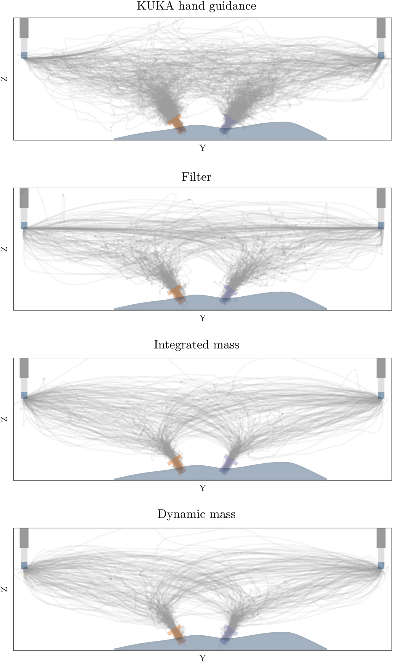
Projection of recorded endoscope tip movement paths to the YZ plane (front view) for each admittance control map (32 × 8 movement paths each) with overlaid start poses and target trocar poses (overlaid manually).
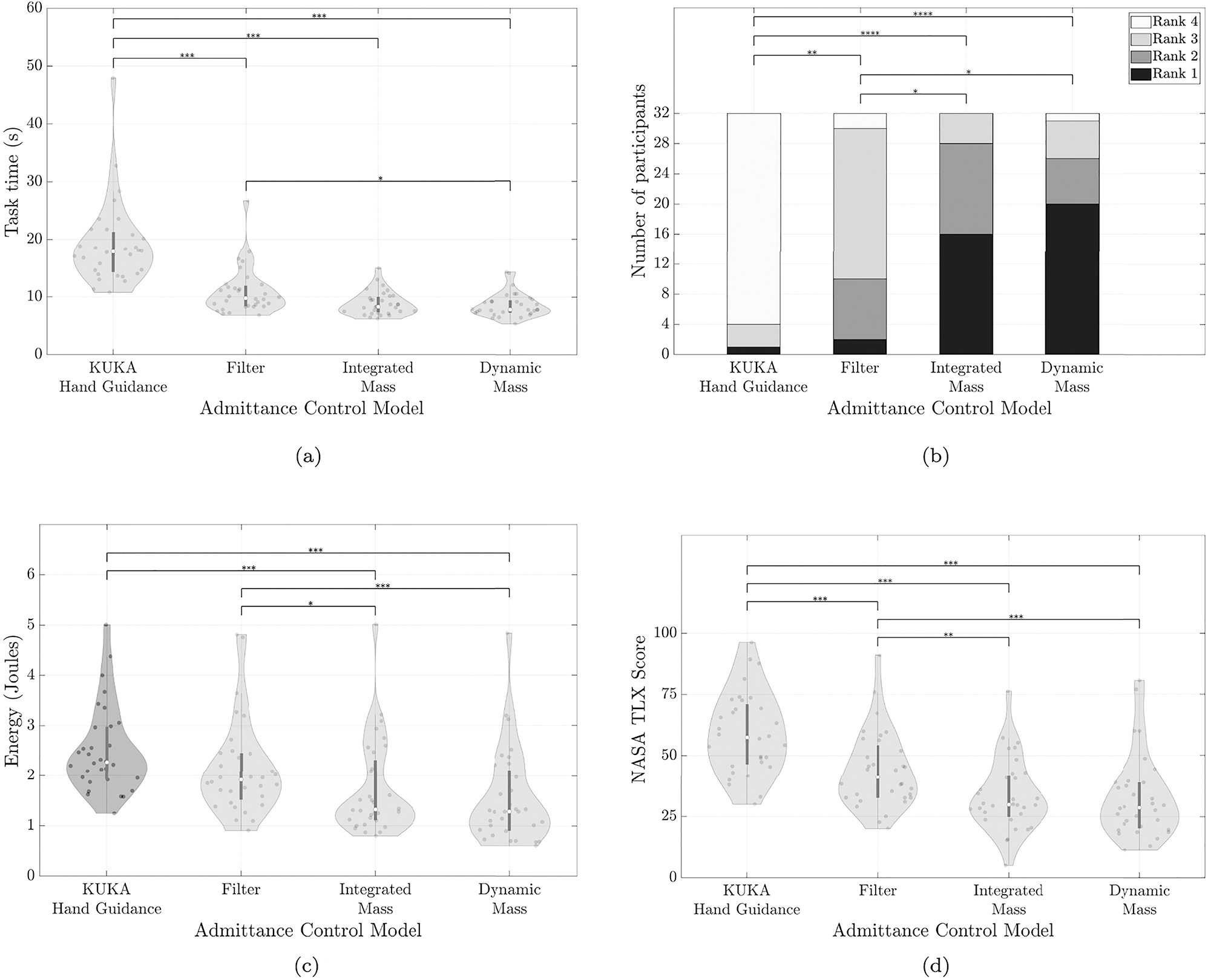
Outcome summary: numerical metrics (a, c, d) for each map are shown as violin plots with raw data points overlaid as dots. The white dot denotes the median, and the bar in the center of each violin denotes the interquartile range from 1st to 3rd quartile. Rank data (b) is shown as a stacked bar plot. Horizontal bars on the top indicate significant differences in the respective statistical test (2-way ANOVA for a, c, d and Friedman’s test for b). The number of asterisks indicates the level of significance with *p < 0.05, **p < 0.01, ***p < 0.001. (a) Violin plot of the average task time taken by each participant to complete the eight tasks with each admittance control map. A lower task time implies that the participant completed tasks faster. (b) Stacked bar plot of the user preference rank. Stacked bars correspond to the number of participants ranking the map 1st (bottom, dark) to 4th (top, light). A darker bar indicates a more often preferred admittance control map. (c) Violin plot of the average energy input by the participant. In KUKA hand guidance map (darker grey), participants were allowed to use two hands to guide the robot; in this case, the calculated energy is a lower bound estimate. Lower energy implies participants completed tasks with less measured physical effort. (d) Violin plot of the NASA TLX score rating for each map. A lower score implies participants reported less perceived overall workload to complete tasks.
Number of occurrences of movement restart due to moving into robot joint limits.
| KUKA hand guidance | Filter | Integrated mass | Dynamic mass |
|---|---|---|---|
| 11 | 7 | 22 | 10 |
4 Discussion
Our results indicate an ordering of the different maps based on the effort needed to hand-guide a robot: Dynamic mass and Integrated mass required the least effort, followed by Filter, and KUKA hand guidance required the most effort; this ordering was supported by all measured qualitative and quantitative outcomes reflecting effort, performance, and subjective preference of the user study as well. The statistical analysis rejected the null hypothesis for all outcome metrics. There were significant differences between the groups due to the map as a test condition.
The endoscope tip trajectories (Figure 5) showed visually perceivable differences (smoothness and target pose precision) in the recorded kinematic paths in the same ordering as the measured quantitative and qualitative outcomes for the maps. The visualized trajectories support the choice of our outcome metrics and indicate that the different maps caused relevant real-world differences in performed movements.
Even though there was no statistical difference between Integrated mass and Dynamic mass in any metric, it was easier to realize the Dynamic mass since it required fewer parameters to be tuned. Moreover, the number of times users moved the robot into joint limits Table 2 was highest with Integrated mass. Considering these observations along with the results, we recommend Dynamic mass to hand-guide robots with a handle. The Dynamic mass was successfully used in recent similar works, such as to collaboratively move a robot for spine surgery [17], or in endonasal surgery [18]. In our opinion, more complex maps than the Dynamic mass potentially could but would not necessarily provide further advantages because parameter tuning would become more difficult and erroneous. We assume the major remaining limitations to transparency arise from the hardware – noise in measurements, latency in signal transmission, and limits in torque build-up of the actuators.
The KUKA hand guidance required the highest effort, was not intuitive, and the users had to reposition themselves often. We attribute this to the fact that the users had to implicitly control the robot’s shape in addition to the endoscope positioning task, thereby, needed both hands and made the task more challenging. Additionally, the user input was measured at the joints, which did not necessarily move the robot along the user desired direction in the task space. In comparison, users could control the robot with one hand using the other maps, only focusing on the robot’s tip movement. In our opinion, surgeons should be able to move the robot quickly with one hand, only focusing on the tool parts close to the patient.
The mean task time per movement was around 10.51 s lower for Dynamic mass compared to KUKA hand guidance, and shows that when a surgeon repeatedly performs tasks such as tool insertion, retraction, or repositioning, the proper choice of the map has the potential to save time for the complete surgery. Similarly, the average energy input per movement was 38 % lower for Dynamic mass compared to KUKA hand guidance and therefore, surgeons could reduce the effort for tool movement during the surgery. The same is corroborated by the perception of the user in the NASA TLX score.
A significant difference was observed between Filter and KUKA hand guidance in all the metrics except energy (p = 0.056). However, in the experimental setup, we measured only the force applied by the one hand on the handle, and therefore a lower bound estimate of the user-applied forces and torques with the two-handed KUKA hand guidance. Thus, the energy estimate for KUKA hand guidance did not truly reflect the actual input energy, as it is missing the forces applied by the user using the second hand on the robot directly. Accordingly, a missing significant effect between Filter and KUKA hand guidance could have been caused by this less sensitive lower bound measure.
Almost equal number of participants ranked the Dynamic mass and Integrated mass in the first place. Since the study protocol allowed ranking multiple maps equally, seven users placed Dynamic mass and Integrated mass at the same rank. The similarity of both the maps in theory and the minor difference of the time-averaged user input in Integrated mass does not significantly affect the users’ perception when both the maps were empirically tuned to reduce the effort.
Many additional control features could constrain endoscope motion during hand-guided movements, such as blocking certain degrees of freedom or only moving through a trocar location with a remote center of motion (RCM) controller. In our study, we have not yet investigated how hand-guiding with user-controlled enabling and disabling such assistive control features would affect the effort by the user during such insertion movements. While we are convinced that such features would be a promising addition, they typically are superimposed constraints to the maps. Therefore, we are convinced of the importance of this study comparing different bare maps. Furthermore, surgeons must always be able to intuitively move a robot without RCM support or other constraining features, e.g., to move the robot out of their way in case they require direct access to the port.
The setup and the designed tasks were symmetric, and the users’ handedness did not influence the results. Nevertheless, during the experiments, we observed that the robot start poses and trocar poses were designed for an average user height. A few users who were far from an average height repositioning themselves had to reposition more often during task movements; since this was the same for all the maps, we are confident the results within this study are not affected. In our future experiments, we will aim for height-adjustable setups that would let the users work at their preferred patient and trocar height more closely, reflecting an actual surgical scenario.
The paths commanded by the users sometimes resulted in the robot moving into joint limits and occurred most often with Integrated mass. The joint and task space limits are not intuitive and were not shown to the user. Furthermore, obstacles in the setup similar to a real surgery would further constrain the feasible robot motion. With the KUKA hand guidance, users controlled the shape of the robot and thus the motion of the robot in null space, the user could use the map to avoid any obstacles. In the other maps, the Moore–Penrose pseudo inverse was used to calculate inverse kinematics, which minimized the overall robot joint motion, and the users did not have control over the shape of the robot. Therefore, we would like to combine admittance control maps with more advanced inverse kinematics that exploit the robot’s redundancy to stay away from joint limits and obstacles.
In the KUKA hand guidance, the torque measured includes both user input and interaction between tool and environment. In all the other maps, tissue interaction was not measured; the user input force was decoupled and was independent of tool-tip forces. While this can be considered a potential safety hazard, where the user could move the robot against patient tissue without measuring or limiting interaction forces, we consider it important that surgeons can control movements accurately while exerting tool forces on patient tissue. Our decoupled approach allows us to measure interaction forces between tool and environment separately with additional sensors, or directly with force measuring endoscopes [25]. In future work, we would want to use such additional measurements to impose safety limits, provide user feedback, or even allow the user to switch between only considering user input or a differential admittance control map combining both user and environment contacts. Such extensions would not be possible with KUKA hand guidance or other setups where user input measurement is not decoupled from tool environment contact.
In our mock-up surgery setup, we fixed the trocars rigidly to the table to ensure all the users had the same target pose with respect to the robot. A trocar inserted in a human body would move depending on forces applied, potentially increasing the difficulty of similar insertion tasks. However, by sensing tool interactions or using differential admittance control maps, additional challenges such as limiting the interaction forces inside the patient could be addressed. Furthermore, the three proposed admittance control maps allow one-handed guidance, enabling surgeons to hold the trocars with their remaining hand if needed.
A limitation of our study is that the findings are specific to our tuning of the maps. Nevertheless, we spent effort to tune each map to the best independently that was achievable for us in a reasonable time. We are convinced that further fine-tuning would only marginally affect the results.
In some previous work Dynamic mass map was investigated. These investigations showed that a variable damping was beneficial to enforce RCM constraints [18], or adaptive gains were useful to enforce workspace and safety constraints [15]. Our result that Dynamic mass was indeed one of the most promising maps, underlines the importance of their investigations on Dynamic mass maps.
Our findings are likely generalizable to scenarios where users hand-guide robots using a power grasp for macro motion of a tool. Further investigation is necessary to see if the results extend to precise control of the tool within the patient or if a redesigned handle with an additional grasp is needed. We aimed to find intuitive controllers for general tool placement and did not constrain the study to surgeons with experience in hand-guiding endoscopic tools. We do not consider any learning effects and the users repeated the motion only eight times with each map. Although training might affect the user preference, we think it is important for the users to move the tool intuitively from the beginning without training.
5 Conclusions
To hand-guide redundant robots in a surgical scenario, two maps that measured the user input in task space at the tool, Integrated mass and Dynamic mass, were rated equally the best. Considering the ease of tuning and implementation, we recommend the Dynamic mass map to control redundant robots. Zero torque control, such as the KUKA hand guidance was not suitable for the same task. We conclude that the next step is to extend the admittance control map and let surgeons control the robot shape with one hand by learning surgeons’ preferences that avoid quasi-stationary obstacles such as the OR-lamps, or medical personnel.
Funding source: Werner Siemens-Stiftung
Award Identifier / Grant number: MIRACLE II
About the authors

Murali Karnam is a doctoral student at the BIROMED-Lab on a project focused on controllers for intuitive surgeon-robot interaction. He studied Mechanical Engineering (Mechatronics) and a Master’s in Engineering Design from Indian Institute of Technology Madras.

Philippe Cattin is a Swiss Professor of Biomedical Engineering at the University of Basel, and head of the Department of Biomedical Engineering. His research interests include medical image analysis, image-guided therapy, and virtual reality. He has published more than 250 papers, patents, and book chapters, and founded three spin-off companies.

Georg Rauter is Associate Prof. for Surgical Robotics at the BIROMED-Lab. His background is Mechanical Engineering (TU-Graz) and Mathematical and Mechanical Modeling (MATMECA, Bordeaux). In 2014 he received his PhD in robotics from ETH Zurich.

Nicolas Gerig is deputy head of the BIROMED-Lab and Technical Coordinator of project MIRACLE. He obtained his Dr. sc. (2018) and MSc mech. eng. (2013) from ETH Zurich working on robot-assisted training, fall prevention of exoskeleton gait at IHMC robotics, and the Cybathlon BCI competition.
Acknowledgments
We thank Prof. Dr. med. Michael Hirschmann and Prof. Dr. med. Niklaus F. Friederich for his continuous support concerning medical questions. We also thank Frederic Bourgeois, who contributed to make the KUKA FRI package run in the TwinCAT real-time environment, and Aleksandra Ivanovic who contributed to find the best handle location within the scope of her Master’s thesis. We thank Sascha Martin and his team at the Physics Workshop at the University of Basel for their support in manufacturing the handle and robot base structure.
-
Author contributions: All the authors have accepted responsibility for the entire content of this submitted manuscript and approved submission.
-
Research funding: We gratefully acknowledge funding of the Werner Siemens Foundation through the MIRACLE and MIRACLE II project.
-
Conflict of interest statement: The authors declare no conflicts of interest regarding this article.
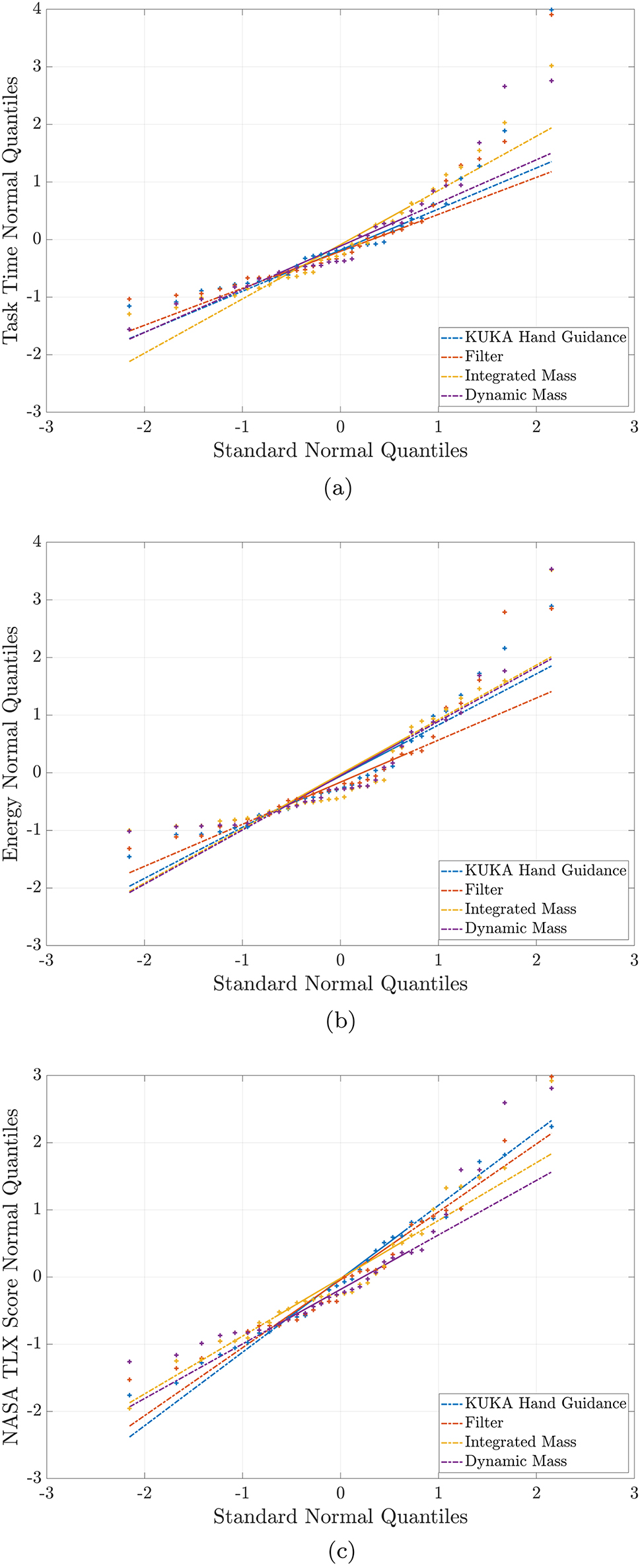
Quantile–quantile plots to ascertain that the data for each measured metric analysed with ANOVA were normally distributed. All plots show the distribution of the normalized data on the Y-axis with respect to a theoretical normal distribution along X-axis. Data points closer to the same colored line imply a more normally distributed data. (a) Task Time. (b) Energy. (c) Nasa TLX Score.
Detailed results of statistical tests for all metrics (rows in gray are not significant).
| Variable | Map main effect | p-value |
|---|---|---|
| Map1–Map2 comparison | ||
| Task time | F 3,127 = 62.87 | <10−4 |
| KUKA hand guidance–Filter | <10−4 | |
| KUKA hand guidance–Integrated mass | <10−4 | |
| KUKA hand guidance–Dynamic mass | <10−4 | |
| Filter–Integrated mass | 0.080 | |
| Filter–Dynamic mass | 0.043 | |
| Integrated mass–Dynamic mass | 0.994 | |
| User rank |
|
<10−4 |
| KUKA hand guidance–Filter | 0.002 | |
| KUKA hand guidance–Integrated mass | <10−4 | |
| KUKA hand guidance–Dynamic mass | <10−4 | |
| Filter–Integrated mass | 0.014 | |
| Filter–Dynamic mass | 0.010 | |
| Integrated mass–Dynamic mass | 0.999 | |
| Energy | F 3,127 = 17.91 | <10−4 |
| KUKA hand guidance–Filter | 0.056 | |
| KUKA hand guidance–Integrated mass | <10−4 | |
| KUKA hand guidance–Dynamic mass | <10−4 | |
| Filter–Integrated mass | 0.027 | |
| Filter–Dynamic mass | <10−3 | |
| Integrated mass–Dynamic mass | 0.581 | |
| NASA TLX | F 3,127 = 40.13 | <10−4 |
| KUKA hand guidance–Filter | <10−4 | |
| KUKA hand guidance–Integrated mass | <10−4 | |
| KUKA hand guidance–Dynamic mass | <10−4 | |
| Filter–Integrated mass | 0.001 | |
| Filter–Dynamic mass | <10−3 | |
| Integrated mass–Dynamic mass | 0.991 |
References
[1] M. K. Welleweerd, F. J. Siepel, V. Groenhuis, J. Veltman, and S. Stramigioli, “Design of an end-effector for robot-assisted ultrasound-guided breast biopsies,” Int. J. Comput. Assist. Radiol. Surg., vol. 15, no. 4, pp. 681–690, 2020. https://doi.org/10.1007/s11548-020-02122-1.Search in Google Scholar PubMed PubMed Central
[2] J. Grischke, L. Johannsmeier, L. Eich, and S. Haddadin, “Dentronics: review, first concepts and pilot study of a new application domain for collaborative robots in dental assistance,” in 2019 International Conference on Robotics and Automation (ICRA), 2019, pp. 6525–6532.10.1109/ICRA.2019.8794139Search in Google Scholar
[3] M. Ureel, M. Augello, D. Holzinger, et al.., “Cold ablation robot-guided laser osteotome (carlo®): from bench to bedside,” J. Clin. Med., vol. 10, no. 3, p. 450, 2021. https://doi.org/10.3390/jcm10030450.Search in Google Scholar PubMed PubMed Central
[4] A. Rothfuss, O. Oesterle, D. Bürgy, et al.., “System and path planning algorithm for low-kv x-ray free-form surface irradiation,” Int. J. Med. Robot. Comput. Assist. Surg., vol. 14, no. 3, p. e1899, 2018. https://doi.org/10.1002/rcs.1899.Search in Google Scholar PubMed PubMed Central
[5] J.-H. So, B. Tamadazte, and J. Szewczyk, “Micro/macro-scale robotic approach for middle ear surgery,” IEEE Trans. Med. Robot. Bionics, vol. 2, no. 4, pp. 533–536, 2020. https://doi.org/10.1109/tmrb.2020.3032456.Search in Google Scholar
[6] N. Preda, F. Ferraguti, G. De Rossi, et al.., “A cognitive robot control architecture for autonomous execution of surgical tasks,” J. Med. Robot. Res., vol. 01, no. 04, p. 1650008, 2016. https://doi.org/10.1142/S2424905X16500082.Search in Google Scholar
[7] J. Sandoval, H. Su, P. Vieyres, G. Poisson, G. Ferrigno, and E. De Momi, “Collaborative framework for robot-assisted minimally invasive surgery using a 7-dof anthropomorphic robot,” Robot. Autonom. Syst., vol. 106, pp. 95–106, 2018. https://doi.org/10.1016/j.robot.2018.04.001.Search in Google Scholar
[8] M. Karnam, M. Eugster, R. Parini, et al.., “Learned task space control to reduce the effort in controlling redundant surgical robots,” in New Trends in Medical and Service Robotics, G. Rauter, P. C. Cattin, A. Zam, R. Riener, G. Carbone, and D. Pisla, Eds., Springer, 2020, pp. 161–168 [Online]. Available at: https://link.springer.com/chapter/10.1007/978-3-030-58104-6_19.10.1007/978-3-030-58104-6_19Search in Google Scholar
[9] KUKA Roboter GmbH, Sensitive Robotics LBR Iiwa, 2017 [Online]. Available at: https://www.kuka.com/-/media/kuka-downloads/imported/9cb8e311bfd744b4b0eab25ca883f6d3/kuka_lbr_iiwa_brochure_en.pdf [accessed: Feb. 09, 2022].Search in Google Scholar
[10] N. Hogan, “Impedance control: an approach to manipulation,” in 1984 American control conference, IEEE, 1984, pp. 304–313.10.23919/ACC.1984.4788393Search in Google Scholar
[11] W. S. Newman, “Stability and performance limits of interaction controllers,” J. Dyn. Syst., Meas., Control, vol. 114, no. 4, pp. 563–570, 1992. https://doi.org/10.1115/1.2897725.Search in Google Scholar
[12] Q. K. Arvid, V. D. K. Herman, and H. S. Arno, “Admittance control for physical human–robot interaction,” Int. J. Robot. Res., vol. 37, no. 11, pp. 1421–1444, 2018. https://doi.org/10.1177/0278364918768950.Search in Google Scholar
[13] S. Haddadin, S. Parusel, L. Johannsmeier, et al.., “The franka emika robot: a reference platform for robotics research and education,” IEEE Robot. Autom. Mag., vol. 29, no. 2, pp. 46–64, 2022. https://doi.org/10.1109/mra.2021.3138382.Search in Google Scholar
[14] R. Taylor, P. Jensen, L. Whitcomb, et al.., “A steady-hand robotic system for microsurgical augmentation,” Int. J. Robot. Res., vol. 18, no. 12, pp. 1201–1210, 1999. https://doi.org/10.1177/02783649922067807.Search in Google Scholar
[15] D. Reyes-Uquillas and T. Hsiao, “Safe and intuitive manual guidance of a robot manipulator using adaptive admittance control towards robot agility,” Robot. Comput. Integrated Manuf., vol. 70, p. 102127, 2021. https://doi.org/10.1016/j.rcim.2021.102127.Search in Google Scholar
[16] J. Lee, K. Kim, W. Kyun Chung, S. Choi, and Y. Soo Kim, “Human-guided surgical robot system for spinal fusion surgery: corass,” in 2008 IEEE International Conference on Robotics and Automation, 2008, pp. 3881–3887.10.1109/ROBOT.2008.4543807Search in Google Scholar
[17] A. Amarillo, E. Sanchez, J. Caceres, and J. Oñativia, “Collaborative human–robot interaction interface: development for a spinal surgery robotic assistant,” Int. J. Soc. Robot., vol. 13, pp. 1–12, 2021. https://doi.org/10.1007/s12369-020-00733-x.Search in Google Scholar
[18] J. Colan, J. Nakanishi, T. Aoyama, and Y. Hasegawa, “A cooperative human-robot interface for constrained manipulation in robot-assisted endonasal surgery,” Appl. Sci., vol. 10, no. 14, p. 4809, 2020. https://doi.org/10.3390/app10144809.Search in Google Scholar
[19] M. Akbari, J. Carriere, T. Meyer, et al.., “Robotic ultrasound scanning with real-time image-based force adjustment: quick response for enabling physical distancing during the covid-19 pandemic,” Front. Robot. AI, vol. 8, p. 62, 2021. https://doi.org/10.3389/frobt.2021.645424.Search in Google Scholar PubMed PubMed Central
[20] Y. Aydin, D. Sirintuna, and C. Basdogan, “Towards collaborative drilling with a cobot using admittance controller,” Trans. Inst. Meas. Control, vol. 43, no. 8, pp. 1760–1773, 2021. https://doi.org/10.1177/0142331220934643.Search in Google Scholar
[21] W. He, C. Xue, X. Yu, Z. Li, and C. Yang, “Admittance-based controller design for physical human–robot interaction in the constrained task space,” IEEE Trans. Autom. Sci. Eng., vol. 17, no. 4, pp. 1937–1949, 2020. https://doi.org/10.1109/tase.2020.2983225.Search in Google Scholar
[22] M. Żelechowski, M. Karnam, B. Faludi, N. Gerig, G. Rauter, and P. C. Cattin, “Patient positioning by visualising surgical robot rotational workspace in augmented reality,” Comput. Methods Biomech. Biomed. Eng. Imaging Vis., vol. 10, pp. 1–7, 2021. https://doi.org/10.1080/21681163.2021.2002192.Search in Google Scholar
[23] M. Karnam, P. Cattin, G. Rauter, and N. Gerig, “Comparing cascaded real-time controllers for an extended KUKA LBR iiwa robot during physical human-robot interaction,” in Siebte IFToMM D-A-CH Konferenz, Technische Universität Ilmenau, 2021 [Online]. Available at: https://duepublico2.uni-due.de/.Search in Google Scholar
[24] MATLAB, Version 9.5.0 (R2018b), Natick, Massachusetts, The MathWorks Inc., 2018. Available at: https://www.mathworks.com.Search in Google Scholar
[25] L. Fasel, N. Gerig, P. C. Cattin, and G. Rauter, “The SEA-scope: torque-limited endoscopic joint control for telemanipulation or visual servoing through tendon force control with series elastic actuation,” in 2021 International Symposium on Medical Robotics (ISMR), IEEE, 2021.10.1109/ISMR48346.2021.9661497Search in Google Scholar
Supplementary Material
This article contains supplementary material (https://doi.org/10.1515/auto-2023-0063).
© 2023 the author(s), published by De Gruyter, Berlin/Boston
This work is licensed under the Creative Commons Attribution 4.0 International License.
Articles in the same Issue
- Frontmatter
- Editorial
- Special issue: Minimal-invasive robotics
- Methods
- Musculoskeletal model-based control strategy of an over-actuated glenohumeral simulator to assess joint biomechanics
- Qualitative and quantitative assessment of admittance controllers for hand-guiding surgical robots
- Continuum robot actuation by a single motor per antagonistic tendon pair: workspace and repeatability analysis
- Development of an AI-driven system for neurosurgery with a usability study: a step towards minimal invasive robotics
- Compact flexible actuator based on a shape memory alloy for shaping surgical instruments
- Shape-sensing by self-sensing of shape memory alloy instruments for minimal invasive surgery
- Minimally invasive in situ bioprinting using tube-based material transfer
- Applications
- Deep learning assisted intraoperative instrument cleaning station for robotic scrub nurse systems