Continuum robot actuation by a single motor per antagonistic tendon pair: workspace and repeatability analysis
-
Christian Marzi
Christian Marzi graduated from KIT (Karlsruhe, Germany) in Electrical Engineering and Information Technologies. In his studies he focussed on optical and medical engineering. Currently, he is pursuing his PhD at the KIT Faculty of Informatics in Research on Medical Robotics.
 ,
Felix Buck
,
Felix Buck
Felix Buck graduated from KIT (Karlsruhe, Germany) in Mechanical Engineering. In his studies he focussed on mechatronics and medical engineering. Currently, he works as an development engineer for medical devices at DMTpe GmbH in Nufringen, Germany.
and
Franziska Mathis-Ullrich
Franziska Mathis-Ullrich is professor for surgical robotics at the Friedrich-Alexander-University Erlangen-Nürnberg (FAU) at the Dep. Artificial Intelligence in Biomedical Engineering.Before joining FAU in 2023, she has been an assistant professor at the Karlsruhe Institute of Technology (KIT) since 2019. Her primary research focus is on minimally invasive and cognition controlled robotic systems and embedded machine learning with emphasis on applications in surgery. She received her B.Sc. and M.Sc. degrees in mechanical engineering and robotics in 2009 and 2012 and obtained her Ph.D. in 2017 in Microrobotics from ETH Zurich, respectively.

Abstract
Continuum robots for application in medicine are of high interest in recent research. However, as most systems in literature show complex and large actuator units, setting up such a system can be time consuming, costly and results in a bulky system, unsuitable for the spatial requirements given in surgical scenarios. In this work, a compact, efficient continuum robotic system is presented. A pair of two antagonistic tendons is controlled by a single servo motor instead of single tendon actuation. This way, the actuator footprint is maintained at a minimum size and the method results in a simpler setup. The resulting 260 mm long robot with 9.9 mm diameter achieves a repeatability with an error of maximum 1.8 % of its length. In future work, this work serves as a basis for integration of various sensing modalities in continuum robots and evaluation of control algorithms.
Kurzfassung
Kontinuumroboter sind stark im Fokus aktueller medizinrobotischer Forschung. Da die meisten der in der Literatur vorgestellten Systeme jedoch komplexe und große Aktoreinheiten aufweisen, kann das Erstellen eines solchen Systems in aufwendigen, kostenintensiven und sperrigen Aufbauten resultieren, welche ungeeignet für die räumlichen Anforderungen des Einsatzes in medizinischen Szenarien sind. In dieser Arbeit wird ein einfaches, effizientes kontinuumrobotisches System vorgestellt, in welchem ein antagonistisches Paar von Kabelzügen durch einen Servomotor bewegt wird, anstatt jedes Kabel durch einen einzelnen Motor zu treiben. Auf diese Weise kann die Grundfläche der Aktoreinheit klein gehalten werden und die Methode resultiert in einem einfacheren Aufbau. Der resultierende 260 mm lange Roboter mit 9,9 mm Durchmesser erreicht eine Wiederholgenauigkeit von 1,8 % seiner Länge. In zukünftigen Arbeiten dient er als Basis für die Integration von verschiedener Sensormodalitäten in Kontinuumroboter und zur Evaluation von Steueralgorithmen.
1 Introduction
1.1 Motivation
Usually, minimally invasive surgery is conducted with rod-shaped, rigid instruments. This represents the standard of care in a lot of manual as well as many robot-assisted interventions such as laparoscopic, eye, or brain surgery. However, controllable flexible instruments and robots can provide significant benefit by increased dexterity, increased workspace, and capability of obstacle avoidance. Therefore, the research on continuum robots (CRs) for the application in medicine is flourishing and commercial systems such as the Da Vinci SP or Ion and Auris Health’s MONARCH Platform have been certified for use in the operating room (OR). Recent literature presents various technologies for realization of a CR such as concentric tubes [1, 2], steerable needles [3], magnetically actuated CRs [4], as well as pneumatically actuated soft robots [5, 6]. Tendon-driven CRs form one of the most simple, yet effective way for implementation; an elastic backbone provides stability and restoring force for the robot’s structure, which is actuated by pulling tendons that are mounted parallel to the robot’s body. Lateral tendon displacement is often confined by spacer discs [7, 8]. A single segment of a tendon-driven CR is typically actuated by three or four tendons to allow for 2-degrees of freedom (DOFs) bending. Each of these tendons is driven by a single motor, thus, resulting in a set of 3n to 4n motors for a CR of n segments. Some approaches use this over-actuation for additional DOFs (torsion or translation) or additional functionalities like variable stiffness but often it remains unused. The need for the number of motors results in typical tendon-driven CRs exhibiting large actuation units underneath the actual robot body. Especially, if power supply and hardware interfaces are taken into account as well, a CR setup often requires a large footprint and volume for integration. As space in the OR is highly limited in medical application scenarios, technical systems must effectively fit into space requirements. Robotic applications in the OR are thus often limited by the space around the patient being required for surgical staff and various other instruments.
1.2 Contribution
Actuation miniaturization has been identified as one of the open challenges in CR research [7, 9]. Therefore, this work presents a method to reduce the actuator unit’s footprint by driving an antagonistic pair of tendons with a single servo motor. This principle is applied to set up a 2-segment CR for medical robotics research. Force measurement is implemented on each tendon individually to allow for tendon force based models. Sensory feedback on tendon force thus can be applied to improve kinematic control or derive contact information of the robot to its environment. With a length of 260 mm and 9.9 mm width the minimally-invasive robot is designed with medical application such as laparoscopic or gastroenterologic interventions in mind. The robot is designed as a research platform to be easily accessible to researchers and students. Sensory feedback on tendon force thus can be applied to improve kinematic control or derive contact information of the robot to its environment.
Similar approaches of antagonistic tendon actuation have been presented in more industrial, agricultural or underwater large scale applications [7, 10], [11], [12], [13]. Here, non-medical applications often allow for larger diameter robot bodies, simplifying actuator integration. For medical application common maximum robot diameters are set to approximately 10 mm, depending on the intervention. Rigid link and serial actuators for medical interventions are often driven by antagonistic cables, and equipped with force sensing as well [14, 15]. Antagonistic tendon actuation of CRs with focus on medical application can be found in [16, 17]. Hong et al. focuse on Maxillary Sinus Surgery and develop a specialized actuator for this situs. The authors present a system with two segments. The distal 2-DOF-segment is driven antagonistically with just one motor. The proximal 1-DOF-segment incorporates two separate tendons pairs for one single plane of motion but providing variable stiffness by varying tendon tension. For tendon force measurement load cells are suspended on the tendons [16]. Amanov et al. present a complex design also incorporating tendon force sensing but with a single axial force sensor for each pair of tendons. While this allows for measurement of tension for two tendons with just one sensor, the measured force always represents the difference of both tendons’ tension [17].
Besides footprint reduction, reducing the number of servo motors increases the potential to economize CR integration into medical robotic instruments and assistant systems regarding cost and weight. This can accelerate CR research and make it more accessible. Furthermore, a simpler actuation unit may enable higher number of segments (i.e., DOFs) and potentially simplify their control.
This work makes use of the antagonistic principle to investigate a simple but effective CR platform suitable for usage in continuum robotic research, especially with focus on biomedical applications. The system’s general design is illustrated in Figure 1, the final setup is presented in Figure 6. To offer this system as an open-source research platform to the scientific community, all construction files and code are published on GitHub.[1]

The proposed continuum robotic platform with two segments as CAD render in various poses.
2 Methods
2.1 Antagonistic actuation principle
When actuating one of the three or four tendons of a conventional tendon-driven CR, each motor can achieve a deflection of the robot’s body simply in one positive direction. For a negative deflection, an opposing motor (or the combination of two opposing motors in the case of three tendons per segment) is necessary. Here, in order to enable positive and negative deflection along one DOF using one motor only, the proximal end of one tendon is wound around the rotor of the motor clockwise and the antagonistic tendon is wound around the same rotor anticlockwise. This design results in shortening of one tendon (to a length of l S ) and elongation of the antagonistic tendon (to a length of l L ) during motor rotation. This actuation principle is visualized in Figure 2. One segment of a CR with a set of n S spacers per segment is depicted in a bent state on one DOF. l BB denotes the length of the backbone, r T the distance of tendon routing and backbone at the spacers. When constant curvature is assumed, the backbone forms to an arch of radius r BB which spans over an angle of α BB . A single section in between two spacers spans over α P and requires a tendon length of l SP . The following geometric relations can be derived from the drawing in Figure 2:

Drawing of the antagonistic principle with dimensions and symbols. Rotation of the tendon drum shortens the inner tendon and results in bending of the actuator. The outer tendon is lengthened simultaneously. Rotation in the other direction results in bending in the opposing direction.
In combination, the shortend length of the tendon is given by
and similarly the elongated tendon length is determind to
The shortening Δl S requires a rotation (in rad) of the motor and tendon of
where r td is the radius of the tendon drum.
Given this rotation, sufficient antagonistic tendon is unwound from the spool for the necessary elongation Δl L as
When the motor is rotated in negative direction past the neutral position, the antagonistic tendon is shortened and the segment bends in the opposite direction. Thus, one motor can achieve actuation of a full DOF actuation. The inequality in Eq. (7) results in slacking of the tendons. This is counteracted in the presented method by introduction tension springs picking up slacking tendon (see Section 2.3).
2.2 Robot actuation
The antagonistic principle, presented in Section 2.1 is used to set up a 4-DOF tendon-driven CR. It consists of two segments, each of which is actuated by two antagonistic tendon pairs aligned in orthogonal planes along the robot’s backbone. Each segment has a length of 130 mm resulting in a total robot body length of 260 mm. Respectively, the robot is actuated by only four motors for a total of four actuated DOFs. Here, pulse width modulation (PWM)-controlled servo motors (SF3218MG, SunFounder, Shenzhen, China) with a range of motion of 270° and a maximum torque 2.05 Nm are used to rotate the tendon drum and lengthen and shorten the tendons, respectively. With a given r td of 6.0 mm a maximum force of 341 N can be applied on the tendons. The servos are installed to provide equal range of motion in both directions and φ i,0 = 0° is defined as the servo angle of motor i which represents the neutral position of a segment. Accordingly, actuator space is given by q = {φ 1, φ 2, φ 3, φ 4} with φ ∈ [−135°, 135°]. φ 1 and φ 2 control the proximal segment 1, φ 3 and φ 4 control the distal segment 2.
The robot’s body is built with a backbone from nickel titanium alloy (NiTi) wire of diameter d bb . Due to its superelasticity, the NiTi-backbone can restore its shape from extreme bending without plastic deformation. Spacer disks to guide the tendons are fabricated by SLS printing (Clear Resin and Form3 3D-printer, Formlabs, Somerville, Massachusetts, USA). The robot is assembled by hand. For alignment of spacer disk rotation and distance, a 3D-printed template was used. The tendons are routed pairwise through a 1 mm diameter hole with distance r t to the backbone. Figure 3 shows the spacer design and the fully assembled robot body. The robot’s dimensions and parameters used are presented in Table 1.

The CR body unit. (a) End-spacer (b) spacer design. (c) Body overview. (d) Segment dimensions.
Table of robot design parameters and dimensions.
| Dimension | Symbol | Value |
|---|---|---|
| Robot length | l BB | 260 mm |
| Robot diameter | d r = | 9.9 mm |
| Number of segments | n S = | 2 |
| Segment length | l s = | 130 mm |
| Sections per segment | n S = | 8 |
| Spacer thickness | t s = | 1.5 mm |
| Tendon drum radius | r td = | 6.0 mm |
| Tendon routing radius | r t = | 3.5 mm |
| Backbone diameter | d bb = | 1.0 mm |
| Base plate side length | a bp = | 230 mm |
To set up a proof-of-principle for evaluation, the robot’s backbone is mounted vertically on a SLA-printed base. The motors are tightly arranged around the base’s center. Tendons are made from high-modulus polyethylene fibers (BeastMaster AX Round Dyneema, Shimano, Osaka, Japan), a material providing high tensile strength and tear resistance. The tendon is wound around the drum three times and the end is securely clamped at the drum using a screw. To avoid entanglement, the two antagonistic tendons are wound around the drum at different axial positions with a distance of 5 mm on the tendon drum. From the tendon drum, each tendon is routed to a load cell unit and back to the robot’s base. Here, deflection pulleys guide the tendons through a channel in the robot base and into the robot’s body.
2.3 Tendon force sensing
Tendon force sensing is implemented on each tendon separately. Therefore, each of the eight tendons is routed from the servo to a pulley, mounted on a load cell. Here, a tensioning mechanism with springs was implemented to reduce slack. Tendon angles and pulley support are designed such that the tensioning mechanism has no influence on the measured force F LC . The latter relates to tendon force F T as in
From the load cell, the deflection pulley redirects the tendon trough the robot’s base into its body. Figure 4 provides multiple views to visualize the tendon routing. Based on preliminary experimentation, the load cells (Miniature LC TAL220B Sparkfun, Boulder, Colorado, USA) are dimensioned for a maximum nominal force of 50 N. The sensor values of the load cells are digitized by a 4-channel Wheatstone bridge (PhidgetBridge 4-Input, Phighets, Calgary, Canada).

Tendon routing in the actuator unit. From the servo’s tendon drum, each tendon is routed to the load cell and through the robot base into the robot body.
The complete robotic setup consisting of robot base, the CR body, motors and load cells is mounted on a square aluminum base plate with a bp = 230 mm side length. At the bottom of the plate, space is used for 5 V power supply (50 W), microcontroller for servo control, two Wheatstone bridges for load cell read-out, as well as additional sensing hardware. The complete platform is mounted on feet of 40 mm height.
2.4 Control interface
To allow for versatility and best integration in a research setting, the robot interfaces directly to the Robot Operating System (ROS)[2] via a connected PC. An Arduino Uno (Arduino S.r.l., Monza, Italy) is used for control of the servo motors. Using the rosserial package,[3] a publisher is written that subscribes to topics for each servo motor’s rotation and is set via a PWM-signal for each motor. The load cell’s measurement bridges are equipped with an USB-interface and raw data are read out and published to ROS via the phidgets_driver package.[4]
3 Robot evaluation
To evaluate the robot, the main characteristics of workspace and positioning repeatability are examined. The evaluation setup consists of the robot as described in Section 2 connected to a ROS-network to be driven to certain motor configurations and the position of both segment’s end-spacers is sampled. As a ground truth for the position of the end-spacers, a hand-operated 3D-measuring arm (FARO Platinum, Faro Technologies Inc., Lake Mary, Florida, USA) with measuring precision of 0.037 mm is used. The segments’ end-spacers and the robot’s base were designed with multiple registration features which were sampled using the metrology arm. These features allowed to determine the center points of the spacer discs and the robot origin. The measuring arm’s sampled values (i.e., 3D-positions in the measurement arm’s coordinate system) where also published to the ROS-network. All data were recorded as rosbags and evaluated using Matlab (The MathWorks Inc, Natick, Massachusetts, USA). The sampled spacer coordinates were transformed to the robot’s base coordinate system to determine positions relative to the robot’s base. This coordinate system was defined with its origin in the mounting point of the backbone in the robot base. The z-axis points upwards along the robot’s ideal neutral position. The x-axis is defined in the plane of the (neutral) tendon pairs from motor 1 and motor 3. The y-axis respectively along the tendon pairs of motor 2 and motor 4 a right-handed coordinate system.
3.1 Robot workspace
To evaluate the robot’s workspace, nine maximally reachable actuator configurations were determined as summarized in Table 2. The poses were chosen to demonstrate maximum elongation (in neutral position) and maximum reach at the circumference of the robot’s workspace around the robot’s base.
Motor configurations, defined to evaluate the continuum robot’s workspace and repeatability.
| Conf. | Workspace evaluation | Repeatability evaluation | |||||||||||||
|---|---|---|---|---|---|---|---|---|---|---|---|---|---|---|---|
| 0 | 1 | 2 | 3 | 4 | 5 | 6 | 7 | 8 | 0 | 1 | 2 | 3 | 4 | 5 | |
| φ 1 | 0° | 135° | −135° | 0° | 0° | 135° | −135° | 135° | −135 | 0° | −8° | −12° | 42° | −125° | −9° |
| φ 2 | 0° | 0° | 0° | 135° | −135° | 135° | −135° | −135° | 135 | 0° | 31° | −134° | −15° | 122° | 75° |
| φ 3 | 0° | −135° | 135° | 0° | 0° | −135° | 135° | −135° | 135 | 0° | −13° | −6° | −44° | 65° | 30° |
| φ 4 | 0° | 0° | 0° | −135° | 135° | −135° | 135° | 135° | −135 | 0° | −56° | −63° | 95° | 54° | 126° |
At each pose, the registration features of the end-spacers of segment 1 and 2 were sampled five times and averaged to reduce the influence of hand-operation of the measuring arm.
To analyze the usability of force sensing on the robot, maximum forces where observed during the workspace analysis. As extreme robot positions are set up, the highest possible forces are expected to apply in this case.
3.2 Repeatability
To evaluate the robot’s motion repeatability, five random motor configurations were generated (cf. Table 2). Starting from neutral pose, these configurations were approached in sequence of the configuration number. At each pose, segment 1 and segment 2 end-spacer positions were sampled as described in Section 3.1. The sequence was repeated and resulting poses were measured again. For each pose and segment, the mean coordinates and the difference of both measurements are evaluated.
4 Results
The complete minimally-invasive robotic system is presented in Figure 6. It incorporates all required control hardware and only interfaces to a 230 V outlet and USB for ROS-connection. While the full system’s footprint is 230 mm × 230 mm, the actuation unit (without load cells) only measures 80 mm × 80 mm. For visualization of the robot’s motion capabilities Figure 5 illustrates the continuum robot body in various configurations.

The continuum robot’s motion capabilities. (a) Neutral pose. (b) Segment 1 bent, segment 2 straight. (c) Equal bending of both segments. (d) Opposing bending of segment 1 and segment 2.

Photograph of the final setup including continuum robot body, force sensing units, power supply and hardware interfaces (on the robots bottom). At the robots origin the coordinate system is drawn.
4.1 Robot workspace
For visualization, the results from Section 3.1 are graphed in a 3D-plot. For each configuration, robot base, both segments’ end-spacer positions are plotted and connected by lines. The plot is shown in Figure 7 in three first angle views and an axonometric projection to illustrate the three-dimensional relations.
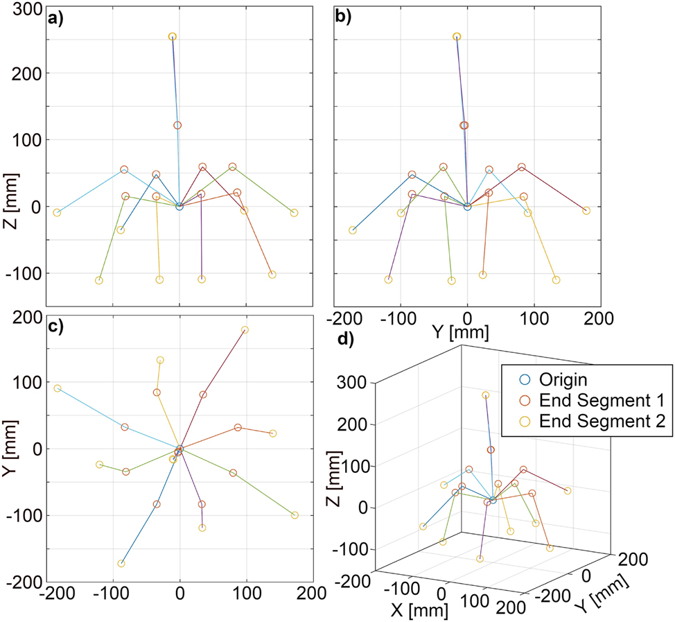
Experimental results from workspace analysis. (a) ZX-plane. (b) ZY-plane. (c) XY-plane. (d) Axonometric projection. Points belonging to the same robot pose are connected via lines.
Analysis of the resulting data indicates the robot being capable of a maximum range of motion of −184 mm–172 mm in X-direction and, −172 mm–178 mm in Y-direction. It could reach a minimum Z-value of −111 mm. Contrary to expectation, it could be observed that the robot’s planes of motion are shifted to the ZX- and ZY-planes by approximately 20°.
The observation of tendon forces resulted in a maximum force reading of F LC = 30.5 N and thus F T = 15.25 N at configuration 8. This shows proper dimensioning of the nominal load cell force and servo moment.
4.2 Repeatability
The values for repeatability analysis are plotted in Figure 8 in a similar manner as described in Section 4.1. Here, the markers denote the mean value of both measurements. The distance of both values is annotated by a sphere with a correlating radius. For better visualization, the radius is scaled up by a factor of 6.

Results from repeatability analysis. (a) ZX-plane. (b) ZY-plane. (c) XY-plane. (d) Axometric projection. The spheres represent the distance of the repeated measurements. Points belonging to the same robot pose are connected via lines.
The difference of the measured coordinate points of segment 1 varies between 1.2 mm and 2.2 mm, while the diameter of the repeatability spheres for segment 2 are between 1.6 mm and 4.76 mm. Relating these repeatability errors to the length of each segment, this equates to a maximum error of 1.7 % for segment 1 and 1.8 % for both segments combined.
5 Discussion
The presented work investigates the implementation of antagonistic tendon actuation on a CR system for application in medical robotic research. The robot’s dimensions of only 9.9 mm diameter but 260 mm length support application in minimally invasive robotic surgery. In contrast to [12], tendons are implemented directly on the motor’s rotors and no slippage was observed. As so far actuator unit miniaturization was out of scope in related literature, comparison of system dimensions is difficult. However, illustrations provided in recent works [8, 11, 18, 19] show actuator units often largely exceeding the robot body’s dimensions. In this work, the pure actuation for a robot of 260 mm length requires a square footprint of 80 mm side length; the complete actuation unit measures 230 mm × 230 mm × 125 mm height (i.e., including tendon force measurement units). The main focus of this work is on space reduction and decreasing the number of required servo motors, as well as optimizing their arrangement. The implemented force measurement unit is not yet optimized and potentially decreases the full system’s spatial requirement further.
Limitations
During workspace analysis of the presented system, a rotatory shift on the bending planes was observed. Presumably, this behavior is due to imprecision in the manual assembly process and inhomogeneities in the robot’s backbone. Further improvement of this issue can possibly be achieved by improved part manufacturing (e.g. micro machined aluminum parts). As this work’s focus was on the mechanical principle and system design, no inverse kinematic is implemented, yet. For proper research of the system’s absolute positioning accuracy such a kinematic will be required. In addition, accurate calibration of the system may mitigate manufacturing and assembly errors. As the presented system makes tendon force measurements available, force based control will be implemented in the future. For this various methods presented in literature (cf. [20, 21]) may serve as a basis to be transferred from single-motor-per-tendon control to one-motor-per-antagonistic-tendon-pair control. Besides kinematic modeling, sensory feedback on the robot’s end-effector’s position or the robot’s body shape could significantly improve the system and serve as a basis for accurate control.
Further design improvements regard the influence of tendon slack resulting from Eq. (7). Slack can lead to tendons loosing contact to routing pulleys and will be reduced by further elaboration of tensioning mechanisms.
6 Conclusions
By controlling an antagonistic tendon pair of a CR with a single motor, the number of motors required for a CR can be minimized to design its actuation unit compactly. In this work, we investigated how this principle can be used to set up a versatile continuum robotic system which can be used as a base for research in minimally-invasive medical robotics or other fields. The system design is published open-source for use in the community.
The CR platform is still limited in its precision due to the lack of inverse kinematic and calibration of manufacturing error, but provides an effective robotic base for research purposes. The presented system will be used in future work to demonstrate integration of sensors in CRs and test algorithms combining intraoperative sensing with CR-control surgical interventions and assistance systems.
About the authors
Christian Marzi graduated from KIT (Karlsruhe, Germany) in Electrical Engineering and Information Technologies. In his studies he focussed on optical and medical engineering. Currently, he is pursuing his PhD at the KIT Faculty of Informatics in Research on Medical Robotics.
Felix Buck graduated from KIT (Karlsruhe, Germany) in Mechanical Engineering. In his studies he focussed on mechatronics and medical engineering. Currently, he works as an development engineer for medical devices at DMTpe GmbH in Nufringen, Germany.
Franziska Mathis-Ullrich is professor for surgical robotics at the Friedrich-Alexander-University Erlangen-Nürnberg (FAU) at the Dep. Artificial Intelligence in Biomedical Engineering.Before joining FAU in 2023, she has been an assistant professor at the Karlsruhe Institute of Technology (KIT) since 2019. Her primary research focus is on minimally invasive and cognition controlled robotic systems and embedded machine learning with emphasis on applications in surgery. She received her B.Sc. and M.Sc. degrees in mechanical engineering and robotics in 2009 and 2012 and obtained her Ph.D. in 2017 in Microrobotics from ETH Zurich, respectively.
-
Author contributions: All the authors have accepted responsibility for the entire content of this submitted manuscript and approved submission.
-
Research funding: None declared.
-
Conflict of interest statement: The authors declare no conflicts of interest regarding this article.
References
[1] Z. Mitros, S. H. Sadati, R. Henry, L. Da Cruz, and C. Bergeles, “From theoretical work to clinical translation: progress in concentric tube robots,” Annu. Rev. Control Robot. Auton. Syst., vol. 5, no. 1, pp. 335–359, 2022. https://doi.org/10.1146/annurev-control-042920-014147.Search in Google Scholar
[2] H. Alfalahi, F. Renda, and C. Stefanini, “Concentric tube robots for minimally invasive surgery: current applications and future opportunities,” IEEE Trans. Med. Robot. Bionics, vol. 2, no. 3, pp. 410–424, 2020. https://doi.org/10.1109/tmrb.2020.3000899.Search in Google Scholar
[3] M. Babaiasl, F. Yang, and J. P. Swensen, “Robotic needle steering: state-of-the-art and research challenges,” Intell. Serv. Robot., vol. 15, no. 5, pp. 679–711, 2022. https://doi.org/10.1007/s11370-022-00446-2.Search in Google Scholar
[4] Z. Yang, H. Yang, Y. Cao, Y. Cui, and L. Zhang, “Magnetically actuated continuum medical robots: a review,” Adv. Intell. Syst., p. 2200416, 2023, https://doi.org/10.1002/aisy.202200416.Search in Google Scholar
[5] H. Su, X. Hou, X. Zhang, et al.., “Pneumatic soft robots: challenges and benefits,” Actuators, vol. 11, no. 3, p. 92, 2022. https://doi.org/10.3390/act11030092.Search in Google Scholar
[6] E. W. Hawkes, L. H. Blumenschein, J. D. Greer, and A. M. Okamura, “A soft robot that navigates its environment through growth,” Sci. Robot., vol. 2, no. 8, p. eaan3028, 2017. https://doi.org/10.1126/scirobotics.aan3028.Search in Google Scholar PubMed
[7] M. Russo, S. M. H. Sadati, X. Dong, et al.., “Continuum robots: an overview,” Adv. Intell. Syst., vol. 5, p. 2200367, 2023. https://doi.org/10.1002/aisy.202200367.Search in Google Scholar
[8] J. Burgner-Kahrs, D. C. Rucker, and H. Choset, “Continuum robots for medical applications: a survey,” IEEE Trans. Robot., vol. 31, no. 6, pp. 1261–1280, 2015. https://doi.org/10.1109/tro.2015.2489500.Search in Google Scholar
[9] Y. Zhong, L. Hu, and Y. Xu, “Recent advances in design and actuation of continuum robots for medical applications,” Actuators, vol. 9, no. 4, p. 142, 2020. https://doi.org/10.3390/act9040142.Search in Google Scholar
[10] N. P. Castledine, J. H. Boyle, and J. Kim, “Design of a modular continuum robot segment for use in a general purpose manipulator,” in 2019 International Conference on Robotics and Automation (ICRA), 2019, pp. 4430–4435.10.1109/ICRA.2019.8794249Search in Google Scholar
[11]] A. Yeshmukhametov, K. Koganezawa, Y. Yamamoto, Z. Buribayev, Z. Mukhtar, and Y. Amirgaliyev, “Development of continuum robot arm and gripper for harvesting cherry tomatoes,” Appl. Sci., vol. 12, no. 14, p. 6922, 2022. https://doi.org/10.3390/app12146922.Search in Google Scholar
[12] A. Yeshmukhametov, K. Koganezawa, and Y. Yamamoto, “Design and kinematics of cable-driven continuum robot arm with universal joint backbone,” in 2018 IEEE International Conference on Robotics and Biomimetics (ROBIO), 2018, pp. 2444–2449.10.1109/ROBIO.2018.8665186Search in Google Scholar
[13] B. Deutschmann, J. Reinecke, and A. Dietrich, “Open source tendon-driven continuum mechanism: a platform for research in soft robotics,” in 2022 IEEE 5th International Conference on Soft Robotics (RoboSoft), 2022, pp. 54–61.10.1109/RoboSoft54090.2022.9762144Search in Google Scholar
[14] L. Fasel, N. Gerig, P. C. Cattin, and G. Rauter, “Tendon force control evaluation for an endoscope with series elastic actuation,” in New Trends in Medical and Service Robotics, G. Rauter, P. C. Cattin, A. Zam, R. Riener, G. Carbone, and D. Pisla, Eds., Cham, Springer International Publishing, 2021, pp. 118–126.10.1007/978-3-030-58104-6_14Search in Google Scholar
[15] M. Eugster, C. Duverney, M. Karnam, N. Gerig, P. C. Cattin, and G. Rauter, “Robotic endoscope system for future application in minimally invasive laser osteotomy: first concept evaluation,” IEEE Trans. Med. Robot. Bionics, vol. 4, no. 3, pp. 621–633, 2022. https://doi.org/10.1109/tmrb.2022.3172471.Search in Google Scholar
[16] W. F. Feng, L. Xie, and G.-Z. Yang, “A two-segment continuum robot with piecewise stiffness for maxillary sinus surgery and its decoupling method,” IEEE/ASME Trans. Mechatron., vol. 27, no. 6, pp. 4440–4450, 2022. https://doi.org/10.1109/tmech.2022.3157041.Search in Google Scholar
[17] E. Amanov, J. Granna, and J. Burgner-Kahrs, “Toward improving path following motion: hybrid continuum robot design,” in 2017 IEEE International Conference on Robotics and Automation (ICRA), 2017, pp. 4666–4672.10.1109/ICRA.2017.7989542Search in Google Scholar
[18] E. Amanov, T.-D. Nguyen, and J. Burgner-Kahrs, “Tendon-driven continuum robots with extensible sections—a model-based evaluation of path-following motions,” Int. J. Robot. Res., vol. 40, no. 1, pp. 7–23, 2021. https://doi.org/10.1177/0278364919886047.Search in Google Scholar
[19] M. Li, R. Kang, S. Geng, and E. Guglielmino, “Design and control of a tendon-driven continuum robot,” Trans. Inst. Meas. Control, vol. 40, no. 11, pp. 3263–3272, 2018. https://doi.org/10.1177/0142331216685607.Search in Google Scholar
[20] F. Janabi-Sharifi, A. Jalali, and I. D. Walker, “Cosserat rod-based dynamic modeling of tendon-driven continuum robots: a tutorial,” IEEE Access, vol. 9, pp. 68 703–68 719, 2021. https://doi.org/10.1109/access.2021.3077186.Search in Google Scholar
[21] M. T. Chikhaoui and J. Burgner-Kahrs, “Control of continuum robots for medical applications: state of the art,” in ACTUATOR 2018; 16th International Conference on New Actuators, 2018, pp. 1–11.Search in Google Scholar
© 2023 the author(s), published by De Gruyter, Berlin/Boston
This work is licensed under the Creative Commons Attribution 4.0 International License.
Articles in the same Issue
- Frontmatter
- Editorial
- Special issue: Minimal-invasive robotics
- Methods
- Musculoskeletal model-based control strategy of an over-actuated glenohumeral simulator to assess joint biomechanics
- Qualitative and quantitative assessment of admittance controllers for hand-guiding surgical robots
- Continuum robot actuation by a single motor per antagonistic tendon pair: workspace and repeatability analysis
- Development of an AI-driven system for neurosurgery with a usability study: a step towards minimal invasive robotics
- Compact flexible actuator based on a shape memory alloy for shaping surgical instruments
- Shape-sensing by self-sensing of shape memory alloy instruments for minimal invasive surgery
- Minimally invasive in situ bioprinting using tube-based material transfer
- Applications
- Deep learning assisted intraoperative instrument cleaning station for robotic scrub nurse systems