
3-dimensional plasmonic nanomotors enabled by independent integration of optical pulling and lateral forces
-
Guillermo Serrera
 ,
Yoshito Y. Tanaka
and
Pablo Albella
,
Yoshito Y. Tanaka
and
Pablo Albella


Abstract
Light–matter interactions generally involve momentum exchange between incident photons and the target object giving rise to optical forces and torques. While typically weak, they become significant at the nanoscale, driving intense research interest in the exploitation of photon recoil to drive micro- and nanostructures. While great progress has been attained in controlling transversal degrees of freedom, three-dimensional movement remains challenging, particularly due to the impractical realization of pulling forces that oppose the direction of incident light. Here we theoretically present a novel nanomotor design that enables independent control over both transverse and longitudinal motion. This design exploits coupling between an azimuthally polarized Bessel beam and a dielectric glass cylinder to realistically achieve optical pulling forces. At the same time, asymmetric plasmonic dimers, embedded within the cylinder, provide lateral motion, through asymmetric scattering under plane wave illumination. We further demonstrate that unwanted displacements and rotations can be restrained, even at long illumination times. Our design unlocks a new degree of freedom in motion control, allowing for pulling, pushing, and lateral movement by simply tuning the polarization or switching between plane waves and Bessel beams.
1 Introduction
At the core of light–matter interaction, photons are scattered or absorbed by objects leading to an exchange or transfer of linear and angular momentum. This, by Newton’s third law, results in optical forces and torques acting back on the interacting objects [1], [2]. The ability to remotely manipulate objects has prompted intense research into microscopic light-driven actuators, looking for the miniaturization and simplification of current systems, with a focus on lab-on-a-chip technologies [3], [4]. These actuators often include fluid pumps [5], [6], valves [7], and mixers [8], as well as motion actuators fueled by strong gradient forces in tightly focused beams [9], [10]. However, reliance on gradient forces imposes some design constraints, including the need for beam steering, its short working range due to the low depth of focus of high NA lenses, and the limitations imposed by diffraction into the light intensity gradient. Most importantly, the interplay between gradient and scattering forces enforces severe limitations on the actuated object’s geometry and material.
All these constraints have motivated the study of scattering forces with plane waves or weakly focused beams as an alternative to optical tweezers and gradient-driven forces. In particular, the exploitation of asymmetric scattering from nanostructures has led to some successful lateral optical nanomotors. These schemes have relied on asymmetric plasmonic assemblies, such as gammadion shapes [11], dimers/trimers resembling Yagi–Uda antennas [12], [13], or dielectric metasurfaces with directional scattering [14]. Combinations of these elements allow for control of different degrees of freedom within the transversal plane, including both translation and rotation.
However, controlling longitudinal motions without gradient forces remains a challenge in this type of devices. ‘Pushing’ forces are a trivial byproduct of light scattering at normal incidences, arising as a direct result of momentum conservation. On the other hand, ‘pulling’ scattering forces are counter-intuitive, since
Nonetheless, the two most successful approaches for realizing optical pulling forces have been the use of Bessel beams [26] and optical tractor beams (OTBs), based on the interference of several obliquely incident plane waves [27], [28]. In both cases, the individual photons exhibit oblique incidence angles θ0. While pulling forces have been successfully achieved using very large angle Bessel beams and OTBs, they are impractical due to their short range [29]. In this respect, azimuthally polarized Bessel beams, coupled to anti-reflective coated dielectric cylindrical waveguides have shown to be an effective approach to reduce angles below 45°, where range is no longer suppressed [30].
While these various techniques for optical pulling exist, their realistic application in the control of longitudinal motion in nanomotors is still missing, and current designs, based on sophisticated responses to different incident polarizations, are not suitable for this purpose.
In this work, we propose a realistic nanomotor design whose motion can be independently controlled in both the transversal plane and the longitudinal axis. A suitable platform for optical pulling was first developed, based on waveguide coupling between an azimuthally polarized Bessel beam and a glass cylinder coated with anti-reflective layers. Then, using this cylinder as the main chassis for the nanomotor, asymmetric plasmonic dimers were strategically placed within the dielectric cylinder to avoid strong interaction with the pulling beam and thus preserving the optical pulling effect. Therefore, a plane wave incidence produces lateral motion, driven by the lateral force from the plasmonic dimers, while incidence with a Bessel beam provides movement on the longitudinal axis via the optical pulling force on the cylinder. Our design enables the selection of motion modes: pulling, pushing, and lateral movements (left-right, forward-backward) by adjusting the polarization or switching between plane wave and Bessel beam illuminations. Furthermore, we demonstrate that the optical pulling force achieved in our system is highly robust against rotations, translations and Brownian motion, furthering the versatility and practical applicability of our device.
2 Conceptual overview and optical pulling platform
As showcased by authors in [30], optical pulling forces (OPFs) benefit from transversely isotropic particles (like cylinders) and beams, with the azimuthal polarization being more efficient in the compromise between pulling force and Bessel beam cone angle. These beams are characterized by an electric field
where E0 is the amplitude, k0 is the beam wavenumber,
The general idea behind our design is illustrated in Figure 1(a) and (b). We exploit the efficient OPF from zero-order azimuthally polarized Bessel beams on dielectric cylinders, and we add plasmonic rod dimers to provide lateral motion. As seen in Figure 1(c), these plasmonic dimers, when illuminated with y-axis polarization at the superposition of their respective resonance (around 980 nm in Figure 1(c)), provide very directional lateral scattering, driving the lateral (x-component) force seen in Figure 1(d) [31], [32], [33]. Meanwhile, the perpendicular polarization at the same wavelength, is characterized by very low and uniform scattering, resulting in negligible optical forces, as shown in Figure 1(d).
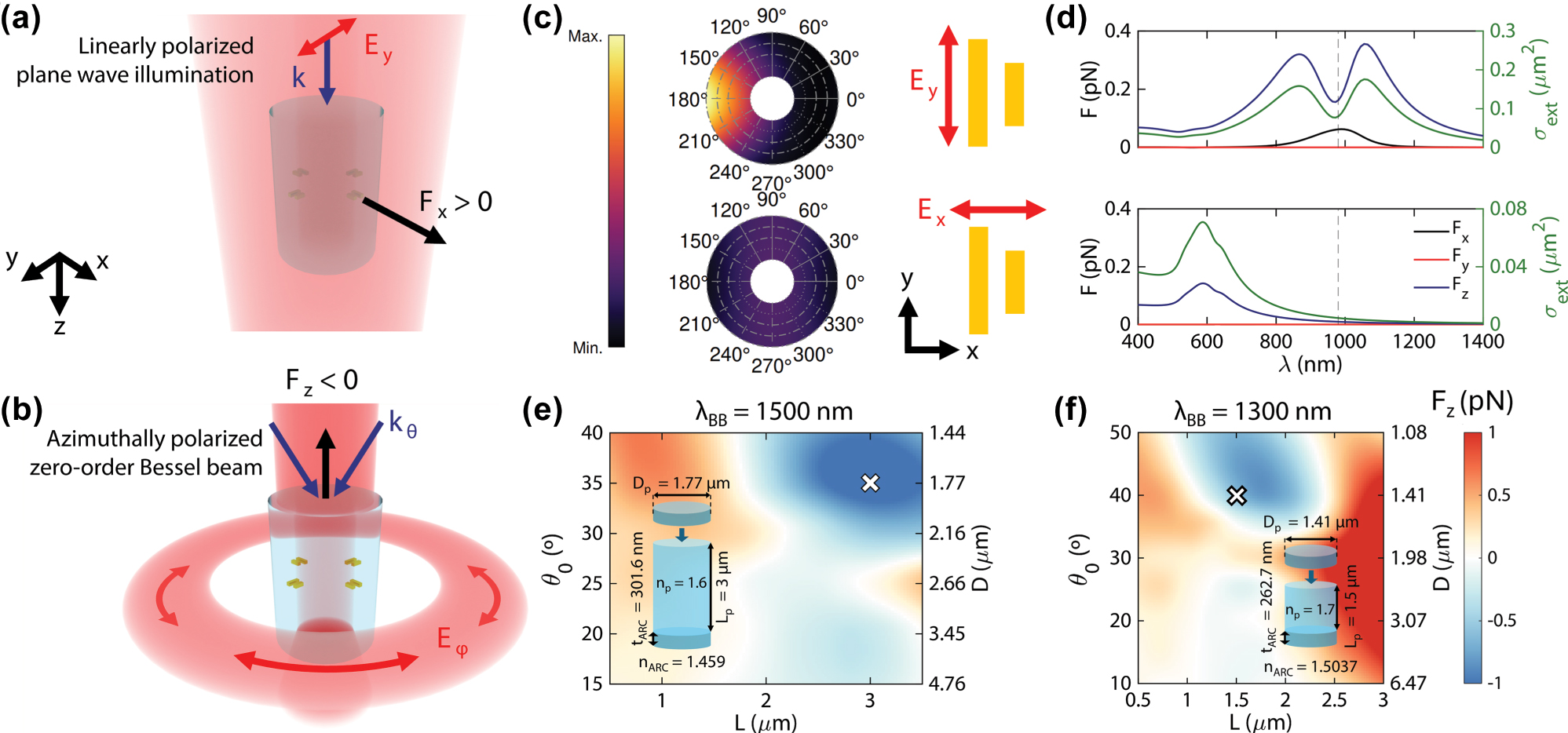
Scheme of the nanomotor’s lateral movement, provided by the plane wave illumination (a) and its pulling force mechanism with the Bessel beam (b). (c) Scattering pattern of plasmonic nanorod dimers at a wavelength of 980 nm, for both parallel (E y ) and perpendicular polarizations (E x ). The nanorods are characterized by lengths of 170 and 130 nm, separated by a distance of 100 nm. Their depth and width are the same, at 50 nm. (d) Optical forces and extinction cross section for the aforementioned dimers and polarizations. The illumination intensity is 0.4 mW μm−2. (e) Longitudinal force on a dielectric cylinder upon interaction with an azimuthally polarized Bessel beam (characterized by angle θ0) at a wavelength of 1,500 nm and a wavelength of 1,300 nm (f). The insets reflect the geometrical and material features of the two selected designs, corresponding to the white crosses in their respective maps. The different-coloured cylinders above and below correspond to the ARCs, whose index is indicated below the cylinders.
As can be seen in Figure 1(d), the optical force exerted in these dimers has a dominant longitudinal (z) component, which closely follows the dimer’s extinction cross-section. This z-component force is also quite large for even moderate illumination intensities (0.4 mW μm−2), meaning that the pulling force exerted by a Bessel beam might be suppressed if strong interaction with the dimers occurs. This interaction can be avoided by employing wavelengths higher than 1,000 nm and a polarization perpendicular to the dimer’s orientation, so that no resonance is excited. To achieve a cylinder design working at such wavelengths, we explore different combinations of Bessel beams (1 mW μm−2 maximum intensity) with wavelengths
The dynamics of a cylinder in an aqueous medium strongly depend on its geometrical aspect ratio, defined as p = L/D, where L is the cylinder’s length and D its diameter. To investigate such different dynamics, we select two suitable configurations characterized by different cylinder length/diameter aspect ratios, as shown in Figure 1(e) and (f). In particular, Figure 1(e) shows the longitudinal (z-component) force map for a 1,500 nm Bessel beam and a 1.6 index cylinder, where long cylinders are generally required to excite the FWM and generate the pulling force, with a maximum negative force of −1.2 pN, located at an angle of 35° (1.77 µm diameter) and a length of 3 µm (2.04 aspect ratio).
On the other hand, Figure 1(f) shows the force map for a 1,300 nm wavelength Bessel beam and a 1.7 index cylinder, where the maximum negative force of −0.6 pN is located at an angle of 40° (1.44 µm diameter) and a length of 1.8 µm. To ensure that we can work with a sufficiently different aspect ratio, here we select a suboptimal configuration (same diameter, length of 1.5 µm) with a lower (1.44) length/diameter aspect ratio.
3 Plasmonic dimer placement for optical pulling preservation and lateral motion
As stated previously, minimizing the interaction with the dimers is key to preserve the pulling force. As shown in Figure 1(d), interaction is minimized for polarizations orthogonal to the dimers, given that the wavelength is sufficiently long as to avoid the resonance of the rod’s short dimension and the intrinsic absorption of gold. However, the complex interaction of the Bessel beam with the nanomotor’s glass chassis might result in complex polarization patterns, meaning that the force exerted on the dimers can be difficult to predict.
To characterize the general properties of the incident field impinging on the dimers, we show in Figure 2(a) the electric field inside and in the vicinity of the cylinder in Figure 1(f) (1.44 µm diameter and 1.5 µm length), upon interaction with its suitable pulling Bessel beam. Cut planes below, in the middle and above the cylinder are featured in Figure 2(b)–(d), with the field’s polarization. As can be seen in Figure 2(a), the field has a similar shape to the incident beam below the cylinder, with a clear azimuthal polarization pattern in Figure 2(d). Meanwhile, in the inner part of the cylinder field gets concentrated around its center due to its higher refractive index. Due to the TE FWM excitation, the field retains its azimuthal polarization (Figure 2(c)). Finally, the field above the cylinder has a more complex shape, owing to interference with the parts of the beam that impinge laterally on the cylinder. However, a close examination in Figure 2(b) shows that the field is generally less focused due to the collimation effect and remains azimuthally polarized.
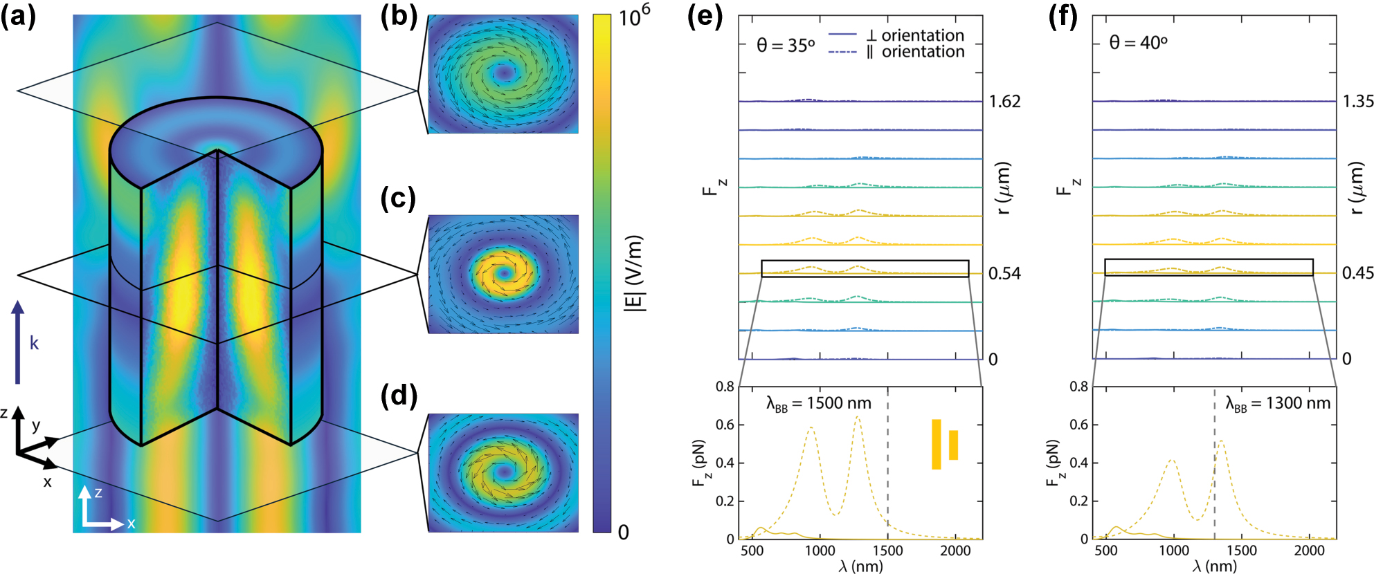
Interaction of plasmonic dimers with Bessel beams. (a) Electric field within the cylinder in Figure 1(f) (1.44 µm diameter, 1.5 µm), upon interaction with a 40°, 1,300 nm Bessel beam, with cut planes below (b), in the middle (c) and above (d) the cylinder, featuring the field polarization with black arrows. Incidence of the beam is in the positive z direction. (e) and (f) Wavelength dependence of longitudinal forces exerted on the asymmetric plasmonic dimers (rods 50 nm wide and deep, 170 and 130 nm long, 100 nm gap) by Bessel beams with angles θ = 35° (e) and θ = 40° (f). The dimers are located at different radial positions r with respect to the beam center. Solid lines represent an orientation of the rods perpendicular to the azimuthal polarization of the beams while dashed lines represent a parallel orientation. The dimers are placed in a background medium (without the pulling cylinder, hence the positive F z values) with refractive indices corresponding to those of the cylinders (n p = 1.6 for the 35° beam and n p = 1.7 for the 40° beam).
In general, the incident field on the dimers will correspond to the same profile of the incident Bessel beam, corrected by the higher refractive index of the cylinder. Thus, we can find the Lorentz’s force exerted on a single nanorod by approximating said rod as a dipole with dipolar moment
p
. For harmonic fields, the time-averaged force
where ω is the angular frequency of light and
B
is its magnetic field. Using the electric field from equation (1) with m = 0 and letting
p
= ɛ
b
α
E
(with
where E φ is the azimuthal field in equation (1). This expression can be further simplified to
where x ρ = k0 sin θ0ρ. As can be seen, a transversal force in the radial direction arises as well as a longitudinal force. Note that the conjugate polarizability α*, at the Frölich condition of a plasmonic nanoparticle, will have a negative imaginary part [36], meaning that the longitudinal force will be positive (pushing force). Both force components can be eliminated by: (1) placing the dipole at zero field points (zeroes of the Bessel function J1(x ρ )), which can be impractical due to the size constraints imposed by the optical pulling force as well as fabrication issues; and (2) minimizing the polarizability, making both force components effectively zero and allowing independent control of pulling and lateral forces.
For rod-like particles, characterized by highly anisotropic polarizabilities, interaction can be suppressed by polarizing light along the shorter dimension of the rod, minimizing and shifting the resonance to lower wavelengths. Although interactions in a dimer can result in more intricate force patterns, a parallel rod dimer, as previously shown in Figure 1(d), can present a similar response to a single rod system. This means that parallel rod dimers, in contrast with other proposals, could be employed to effectively select between transversal and longitudinal motion.
Due to the non-trivial interactions between the rods in a dimer, we propose a semi-analytical coupled dipole approximation (CDA) method approach, following [37], to calculate the optical forces from such beams onto a single plasmonic dimer (see Supplementary Information for details on this method).
We select the same angles and refractive indices featured in Figure 1(e) and (f) and calculate the longitudinal optical force on a dimer formed by the same rods shown in Figure 1(d) (50 nm wide and deep, 170 and 130 nm long), and explore different radial positions within the beam, enough to cover the higher intensity regions. We also consider two different orientations, one oriented along the beam polarization and one perpendicular to it. Due to the nature of CDA simulations, the dielectric cylinder was omitted, and its refractive index (in both cases) was used as the background index for the CDA simulations.
Results are shown in Figure 2(e) (35° Bessel beam, for the 1.6 refractive index cylinder in Figure 1(e)) and Figure 2(f) (40° Bessel beam, for the 1.7 refractive index cylinder in Figure 1(f)). Both figures display a dual peak shape for the parallel orientation, following closely the shape in Figure 1(c), with z-component forces up to 1 pN. As expected from the single-rod behavior, the magnitude of forces correlates with the positions of higher intensities. On the other hand, the perpendicular orientation, characterized by a lower and blue-shifted polarizability, displays a flatter profile, with forces up to 0.1 pN near 500 nm, and near-zero forces for wavelengths higher than 1,000 nm. In particular, the insets of Figure 2(e) and (f) show the force profile for radial positions near the edge of their respective cylinders. These positions can be advantageous, enabling the integration of several dimers within the cylinder that can be operated independently. Despite being high-intensity sites, the exerted force is near-zero when oriented orthogonally to polarization, due to their very low and blue-shifted polarizability. Thus, optical pulling is preserved. We highlight that this result showcases the independent physical mechanisms that induce the two types of forces, with no coupling between them. Additional components for the inset cases in Figure 2(e) and (f) can be found in the Supplementary Information (Figure S5), where it can be seen that, as occurs with a single rod, the transversal forces in dimers can be avoided with a perpendicular orientation with respect to the azimuthal polarization.
Due to the axial symmetry of this design, we can position several dimers within the cylinder, making sure that all of them are oriented perpendicular to the Bessel beam polarization. An illustration of this configuration is shown in Figure 3(a). In this case, the use of 4 dimers allows independent control of movement in the x and y directions upon linearly-polarized plane wave illumination. This is supported by Figure 3(b)–(e), where the optical forces and torques on both cylinders are shown. As expected, the component of force perpendicular to polarization dominates, with a clear peak around 1,100 nm. On the other hand, forces on the polarization axis are small, meaning that movement between the two directions can be independently controlled. For both designs, forces are in the 0.1 pN range, sufficient to overcome Brownian motion and obtain a steady movement speed [12].
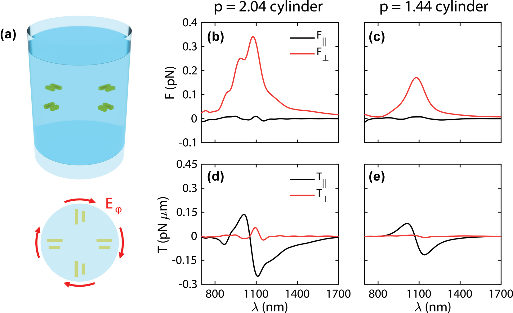
Simulation results for lateral movement. (a) Scheme of a full 3D nanomotor design, with four plasmonic dimers perpendicularly oriented to the azimuthal polarization of a pulling Bessel beam. (b) Optical transversal forces exerted by a 0.4 mW μm−2 plane wave on the nanomotors based on cylinders with aspect ratios 2.04 and 1.44 (c). (d) Optical transversal torques exerted by a plane wave on the same nanomotors. (e). The cylinder with aspect ratio 2.04 contains three layers of plasmonic dimers, in contrast with the 1.44 aspect ratio cylinder, which only includes one. The background refractive index is n b = 1.33.
Looking at the torques, the parallel component dominates, with an oscillating shape around the same wavelength. While the peaks for the perpendicular force component fall within positive torque values (meaning that the cylinder could tumble with time), this effect can be suppressed by using slightly different wavelengths, where the torque can be suppressed.
The longitudinal components of both force and torque (F z and T z ) are provided in the Supplementary Information (Figure S6). The longitudinal force is much larger than either F‖or F⊥, pointing to strong forward movement when using plane wave illumination. As shown in the Supplementary Information, control of the pushing movement can be done independently of lateral movements if out-of-resonance wavelengths are employed. On the other hand, the longitudinal torque T z is around 10 times weaker than the T‖ component in Figure 3, meaning that for such illumination T‖ is the only relevant component.
The scheme described so far only provides translational motion, but a similar strategy can be employed to implement rotational motion. As shown in the Supplementary Information (Figure S8), silver nanorods can be inserted between the dimers. Illumination with circularly polarized light allows transfer of spin angular momentum into the nanorods [38], [39], [40], [41], permitting efficient clockwise and anticlockwise rotations depending on the incident helicity. Furthermore, by placing the rods perpendicular to the azimuthal polarization, the optical pulling force is still preserved.
4 Optical pulling stability in diffusion simulations
The longitudinal force maps, shown in Figure 1(e) and (f), correspond to cylinders fully aligned with the incident beam. However, when nanomotors are immersed in a fluid such as water, they can undergo Brownian motion, meaning that the pulling must be preserved upon small displacements and rotations from the beam center. Furthermore, as shown in Figure 3, interaction with light can induce transversal forces and torques, further prompting the need for stable pulling forces for a realistic application of these nanomotors. In particular, and contrary to optical tweezers, the incident Bessel beams have a ring-shaped maximum intensity, leading to the possibility of gradient optical forces driving the nanomotor away from the beam center [42], [43].
To elucidate the impact of these rotations, we performed FDTD simulations considering displacements from the center along the x axis. As the cylinder moves along the x axis and away from the center, the incident azimuthal polarization becomes similar to a linear y-polarization. Inspired by Figure 3, both the x-component force and the y-component torque will become important and dominate against the other transversal components. Therefore, rotations around the y axis are also considered in simulations.
The stability of the optical pulling effect provided by the Bessel beams is showcased in Figure 4(a) and (b). While a maximum negative force is found at the beam center, pulling is preserved to rotations up to 20° in both cylinders, and for up to 150–200 nm displacements. The expected dominant transversal components of force and torque are shown in Figure 4(c) and (d) (transversal force) and Figure 4(e) and (f) (transversal torque), with insets depicting the non-dominant components. As shown in the insets, the non-dominant components are homogeneous and their contribution can generally be neglected against the dominant components, especially in the case of the longer nanomotor. In contrast, the dominant components of both force and torque resemble those observed in optical tweezers in the ray optics regime [44], leading to equilibrium positions and orientations. The x-component force reaches zero around the center of the beam, with the position of this zero slightly shifting to the left or right depending on the nanomotor angular orientation. Similarly, the y-component torque reaches zero for most angles at the beam center, and this zero is shifted to angles up to 10° (p = 2.04 nanomotor, 40° for the p = 1.44 one) outside the beam center. The non-dominant longitudinal torque T z can be consulted in the Supplementary Information. Once again, the near-zero lateral forces and torques at the beam’s positional and angular center highlight the negligible coupling between the optical pulling force and the lateral forces observed in Figure 3.
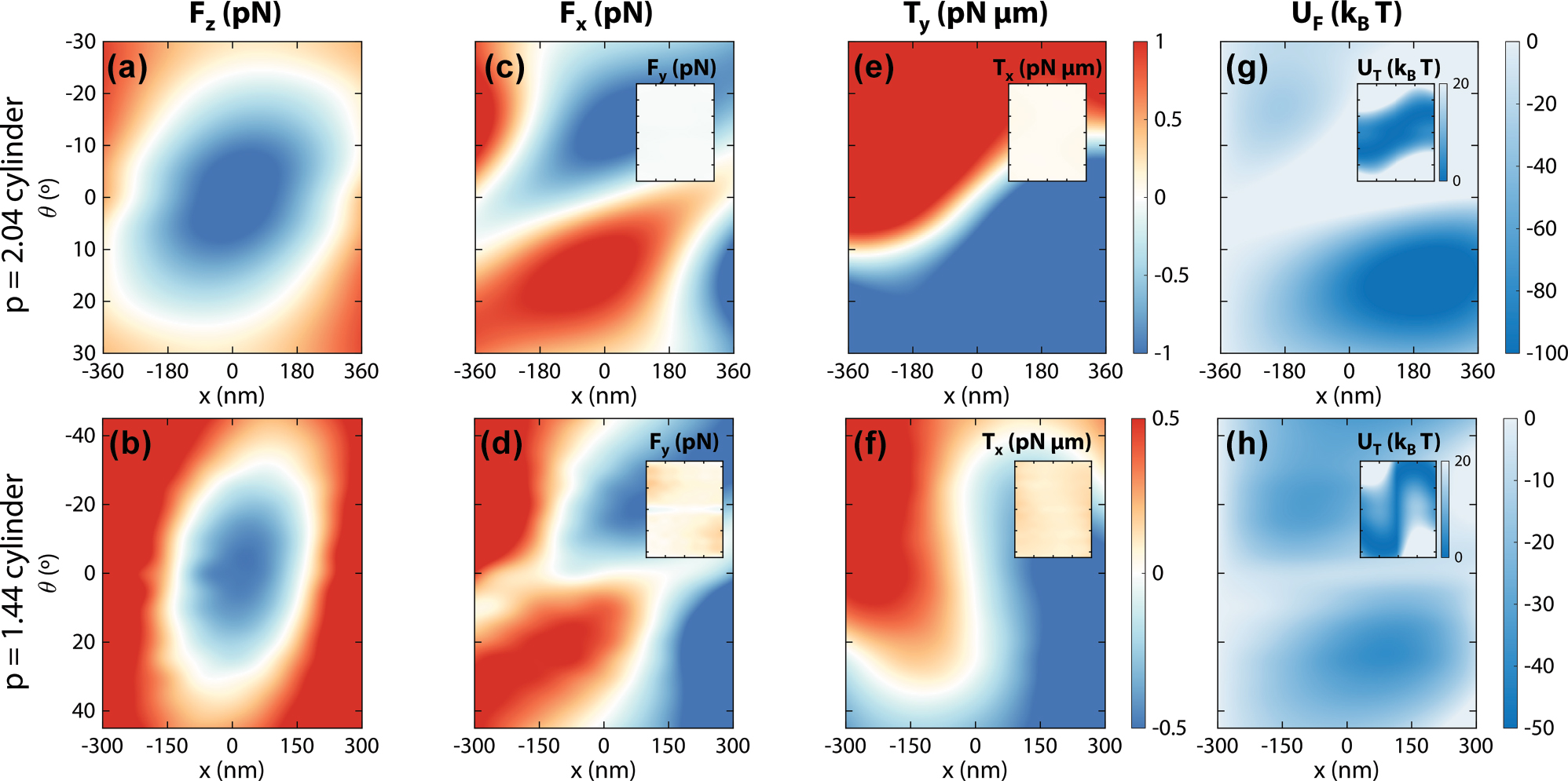
Position and angular dependence of the optical pulling scheme. (a) and (b) Longitudinal force exerted on the p = 2.04 and 1.44 nanomotors by their corresponding Bessel beams at different x positions and tumbling angles θ. (c) and (d) Dominant transversal optical forces (x-component), with the negligible y-component optical forces shown in the respective insets. (e) and (f) Dominant transversal optical torques (y-component), with the negligible x-component optical forces shown in the respective insets. (g) and (h) Potential maps associated with the transversal force (U F ), with the potential associated to the torques (U T ) in the insets. Simulations for this figure include the full 3D-nanomotor system as in Figure 3 (dielectric cylinder plus plasmonic dimers) in a background medium with refractive index n b = 1.33.
These zero positions and orientations point towards equilibrium points of the nanomotor when illuminated with the Bessel beams. For a further understanding of these restoring forces and torques, we compute potentials from both the dominant transverse forces and torques by integration
Ultimately, the closeness of the integration domain to the beam center and the difficulty to apply appropriate boundary conditions to the angular integration in U T , disallows adding the two potentials together for a quantitative total potential, meaning that we must make a qualitative interpretation of their shapes.
In principle, the U T wells, at opposite positions from the ones in U F , should balance a total potential, allowing the nanomotor to travel across all the central region. To address rigorously the non-trivial dynamics in this system, we set up hydrodynamic diffusion simulations (details can be found in the Methods section as well as in the Supplementary Information). We assume an overdamped low-Reynolds-number regime, with external forces given by the dominant components of force and torque from Figure 4. To evaluate the stability of the system, we target a long illumination time of 1 s and run 10,000 simulations per case in order to obtain significative statistical information.
The overall stability of the nanomotors is demonstrated by the results shown in Figure 5. As can be seen in the upper panels of Figure 5(a) and (b), nanomotors are distributed around two different positions (one positive, one negative), which is compatible with the two different potential wells in both Figure 4(g) and (h). The longer nanomotor design also follows a similar shape in its angular distribution. However, the shorter design displays a less bi-morph distribution, with a 0° maximum. This can be explained by the similar U T wells of both designs. As U F wells are much deeper in the first design, the contribution from U T does not allow easy passage between the two potential wells.
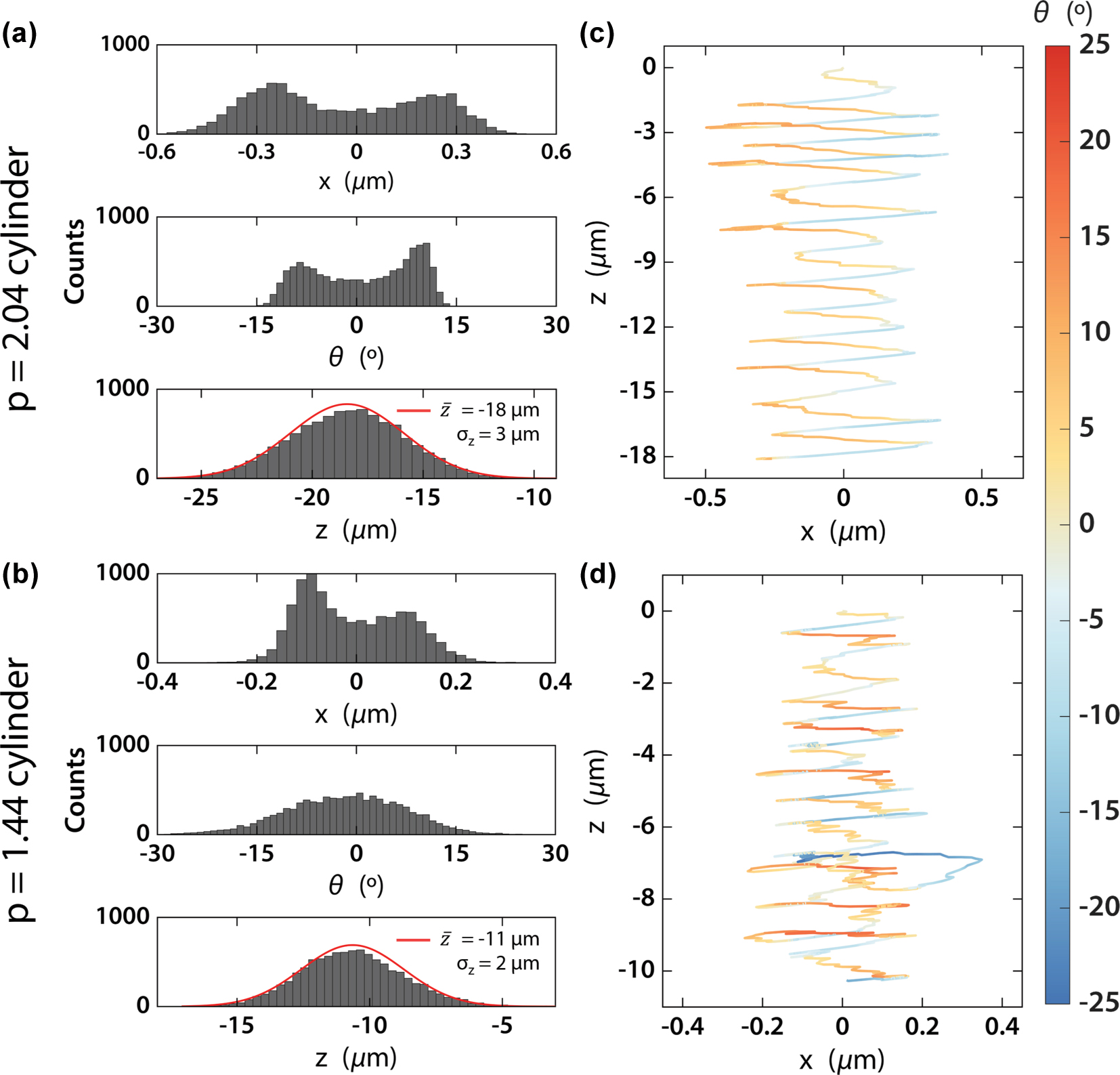
Results of hydrodynamic simulations. (a) and (b) Histograms of the final positions, orientations and longitudinal displacement for the p = 2.04 (a) and 1.44 (b) aspect ratio nanomotors after 1 s illumination. Gaussian fittings are provided for longitudinal positions. (c) and (d) Typical trajectories of the nanomotors, starting at
Meanwhile, the much lower and homogeneous U F wells for the shorter design point to a joint total potential near the beam center and low angles. This bigger contribution from U T in the shorter nanomotor also creates a more homogeneous angular profile in the total potential, which is reflected by the wider angular distribution in Figure 5(b).
This is further confirmed by the typical trajectory of nanomotors, displayed in Figure 5(c) and (d) and characterized by an oscillation between the two different x positions, together with small angular oscillations. This results in the nanomotor being in the pulling region in Figure 4(a) and (b) for most of the illumination time. This, as shown in the lower panels of Figure 5(a) and (b), results in large pulling distances, characterized by Gaussian distributions around 18 and 11 µm, with standard deviations of 3 and 2 µm, respectively. Although the range of both distributions is relatively large (over 10 µm), the standard deviations are comparatively small, leading to moderately narrow distributions. It must be noted that the average values correspond to several times the lengths of the nanomotors, meaning that the speed of nanomotors pulling with moderate intensities is relatively fast. Note that gravitational effects, which could suppose a force contribution close to 0.1 pN (nanomotor masses can be estimated around 10 pg), have been neglected in this analysis. Assuming optical pulling is acting against it, gravitational drag could significantly slow this movement. However, its low magnitude against the optical pulling force means that it can be compensated using a slightly higher illumination intensity.
5 Conclusions
In this work, we have revealed how optical pulling can be integrated synergically into transverse light-driven nanomotors, unlocking a new and important degree of freedom to optical manipulation. Optical pulling can be attained employing azimuthally polarized Bessel beam illumination on carefully designed dielectric cylinders, where a FWM is excited and interference at its end produces a collimation of the incident beam. This scheme allows for an efficient generation optical pulling forces, where high-angle Bessel beams are not required and microscale pulling becomes practical. To combine this approach with transverse movements, plasmonic rod dimers were embedded perpendicular to the azimuthal polarization to allow preservation of the optical pulling effect due to the weak plasmonic interaction. Candidate materials for dielectric cylinders that generate optical pulling force include SU-8, Al2O3, and GaN, which are transparent in the visible and near-infrared regions and can be fabricated with high aspect ratios [45], [46], [47]. Additionally, the plasmonic rod dimers can be precisely embedded into the cylinder of these materials through double-exposure electron beam lithography [11], [12], [13], [14]. Experimental realization of Bessel beams with azimuthal polarizations has been done with appropriate metasurfaces [48].
Then, upon illumination with linearly polarized plane waves, the asymmetric scattering from the metallic dimers results in two independent lateral motions, which can be selected with the incident polarization. Pushing motion can also be obtained as a byproduct of the plane wave illumination for lateral movement and can also be independently controlled by shifting the incident wavelength. As demonstrated in the Supplementary Information, complementary structures can be implemented into the design to efficiently provide controlled rotations [33], [38], [39], [40], [41], which can be independently controlled from other degrees of freedom upon tuning their plasmonic resonances to a different wavelength than the one for translation movement. This can be accomplished using different sizes or materials [36].
Finally, we have demonstrated how this approach is robust enough against rotations, displacements and misalignments, which can be caused by either Brownian motion, the complex Bessel beam profile, or a combination of both. The restoring nature of the transversal forces and torques exerted by the beam produces an intricate potential profile, where the nanomotors oscillate around the beam center while maintaining a straight orientation over long times. This stability, together with the low intensities required for manipulation, greatly enhances the applicability of our approach. We note that other nanomotor designs are characterized by lower height/lateral size aspect ratios (for example, p < 0.1 in [13]). However, these aspect ratios do not consider the strict conditions imposed by optical pulling forces. Nonetheless, this could also be reached by our design, if the wavelength of the Bessel beam is drastically lowered. For that, the plasmonic dimers should be tuned to UV wavelengths, for which the use of materials different than gold would be required [49], [50].
6 Methods
6.1 Numerical electrodynamic simulations
All numerical electromagnetic calculations in this work, excepting those specified with the Couple Dipole Approximation approach in Figure 2 (a detailed discussion can be found in the Supplementary Information), were performed by 3D full-wave electrodynamic simulation software Lumerical FDTD, providing an accurate solution of the Maxwell equations. The non-diffracting Bessel beams were implemented into FDTD using a combination of 60 different total field/scattered field (TFSF) sources, following [51] (more details in the Supplementary Information). The angular dispersion for broadband sources in Lumerical FDTD meant that simulations had to be single-frequency to provide accurate results. This motivated us to use the CDA approach for broadband simulations when considering the plasmonic dimer. Calculation of optical forces F and torques T was done following the Maxwell stress tensor formalism [44]:
where
r
is the position vector,
n
is the outward normal unit vector and the integration is performed over a surface Σ enclosing the nanomotor.
where ɛ
r
is the relative permittivity, ⊗ denotes the dyadic product, ∗ the complex conjugate and
6.2 Hydrodynamic simulations
Hydrodynamic simulations were done following the formalism for diffusion of non-spherical particles in [44]. Due to the axial symmetry and the prevalence of x-component forces and y-component torques against other components, diffusion along the x and z axes, and increments in the β angle (tumbling along the x axis) were considered. Assuming a low-Reynolds-number regime, with external forces F x , F z and torques T y , the movement of the particle after a time step Δt will be given by the overdamped Langevin equation
where the p subindex denotes the particle’s frame of reference. k
B
is the Boltzmann constant and T is the environment temperature.
Following [52], each of the components of this diffusion tensor will be strongly dependent on the cylinder aspect ratio p, and can be extracted using interpolating equations. Finally, w
x
, w
z
and w
β
, accounting for Brownian motion; correspond to a set of random numbers extracted from a multivariate normal distribution with mean zero and covariance
For each time step (Δt = 0.001 s), external forces and torques are extracted from FDTD results based on the particle’s position and orientation, and converted to the particle’s frame of reference. Particle position and orientation are updated based on equation (8), and then the particle’s frame of reference is updated accordingly.
We note that the overdamped approximation in equation (8) must be justified by the ratio of the characteristic time of an optical trap τ
OT
= γ/κ and the momentum relaxation time τ
m
= m
NM
/γ, where
Funding source: Japan Science and Technology Corporation
Award Identifier / Grant number: FOREST Program (JPMJFR213O)
Funding source: Japan Society for the Promotion of Science
Award Identifier / Grant number: JP24H00424 and JP22H05132
Funding source: Agencia Estatal de Investigación
Award Identifier / Grant number: PID2022-139560NB-I00
Acknowledgments
GS thanks the Spanish Ministry of Education for his predoctoral contract grant (FPU21/02296). GS would also like to thank Y. Gutiérrez for her assistance in the development of the CDA calculation method.
-
Research funding: This work acknowledges funding by the MOPHOSYS Project (PID2022-139560NB-I00) from Proyectos de Generación de Conocimiento provided by the Spanish Agencia Estatal de Investigación. This work was supported by Grants-in-Aid for Scientific Research (KAKENHI) (Nos. JP24H00424 and JP22H05132 in Transformative Research Areas (A) “Chiral materials science pioneered by the helicity of light” to YYT) from the Japan Society for the Promotion of Science (JSPS), and JST FOREST Program (No. JPMJFR213O to YYT).
-
Author contributions: All authors contributed to the conceptualization of the study. GS carried out numerical simulations, formal analysis, and writing of the original draft. YYT and PA participated in the discussion of results and supervised the project. All authors have accepted responsibility for the entire content of this manuscript and consented to its submission to the journal, reviewed all the results and approved the final version of the manuscript.
-
Conflict of interest: Authors state no conflict of interest.
-
Data availability: The datasets generated and/or analysed during the current study are available from the corresponding author upon reasonable request.
References
[1] W. Crookes, “Attraction and repulsion caused by radiation,” Nature, vol. 12, no. 294, p. 125, 1875. https://doi.org/10.1038/012125a0.Search in Google Scholar
[2] A. Ashkin, “Applications of laser radiation pressure,” Science, vol. 210, no. 4474, pp. 1081–1088, 1980. https://doi.org/10.1126/SCIENCE.210.4474.1081.Search in Google Scholar
[3] J. Glückstad, “Sorting particles with light,” Nat. Mater., vol. 3, no. 1, pp. 9–10, 2004. https://doi.org/10.1038/nmat1041.Search in Google Scholar PubMed
[4] J. Qin, X. Wu, A. Krueger, and B. Hecht, “Light-driven plasmonic microrobot for nanoparticle manipulation,” Nat. Commun., vol. 16, no. 1, pp. 1–9, 2025. https://doi.org/10.1038/s41467-025-57871-x.Search in Google Scholar PubMed PubMed Central
[5] S. Maruo and H. Inoue, “Optically driven micropump produced by three-dimensional two-photon microfabrication,” Appl. Phys. Lett., vol. 89, no. 14, 2006, Art. no. 144101. https://doi.org/10.1063/1.2358820/331953.Search in Google Scholar
[6] S. Maruo and H. Inoue, “Optically driven viscous micropump using a rotating microdisk,” Appl. Phys. Lett., vol. 91, no. 8, 2007, Art. no. 084101. https://doi.org/10.1063/1.2768631/326519.Search in Google Scholar
[7] A. Terray, J. Oakey, and D. W. M. Marr, “Microfluidic control using colloidal devices,” Science, vol. 296, no. 5574, pp. 1841–1844, 2002. https://doi.org/10.1126/science.1072133.Search in Google Scholar PubMed
[8] S. L. Neale, M. P. Macdonald, K. Dholakia, and T. F. Krauss, “All-optical control of microfluidic components using form birefringence,” Nat. Mater., vol. 4, no. 7, pp. 530–533, 2005. https://doi.org/10.1038/nmat1411.Search in Google Scholar PubMed
[9] D. G. Grier, “A revolution in optical manipulation,” Nature, vol. 424, no. 6950, pp. 810–816, 2003. https://doi.org/10.1038/nature01935.Search in Google Scholar PubMed
[10] U. G. Būtaitė, G. M. Gibson, Y. L. D. Ho, M. Taverne, J. M. Taylor, and D. B. Phillips, “Indirect optical trapping using light driven micro-rotors for reconfigurable hydrodynamic manipulation,” Nat. Commun., vol. 10, no. 1, pp. 1–10, 2019. https://doi.org/10.1038/s41467-019-08968-7.Search in Google Scholar PubMed PubMed Central
[11] M. Liu, T. Zentgraf, Y. Liu, G. Bartal, and X. Zhang, “Light-driven nanoscale plasmonic motors,” Nat. Nanotechnol., vol. 5, no. 8, pp. 570–573, 2010. https://doi.org/10.1038/nnano.2010.128.Search in Google Scholar PubMed
[12] Y. Y. Tanaka, P. Albella, M. Rahmani, V. Giannini, S. A. Maier, and T. Shimura, “Plasmonic linear nanomotor using lateral optical forces,” Sci. Adv., vol. 6, no. 45, p. eabc3726, 2020. https://doi.org/10.1126/sciadv.abc3726.Search in Google Scholar PubMed PubMed Central
[13] X. Wu, R. Ehehalt, G. Razinskas, T. Feichtner, J. Qin, and B. Hecht, “Light-driven microdrones,” Nat. Nanotechnol., vol. 17, no. 5, pp. 477–484, 2022. https://doi.org/10.1038/s41565-022-01099-z.Search in Google Scholar PubMed
[14] D. Andrén, D. G. Baranov, S. Jones, G. Volpe, R. Verre, and M. Käll, “Microscopic metavehicles powered and steered by embedded optical metasurfaces,” Nat. Nanotechnol., vol. 16, no. 9, pp. 970–974, 2021. https://doi.org/10.1038/s41565-021-00941-0.Search in Google Scholar PubMed
[15] J. Chen, J. Ng, Z. Lin, and C. T. Chan, “Optical pulling force,” Nat. Photonics, vol. 5, no. 9, pp. 531–534, 2011. https://doi.org/10.1038/nphoton.2011.153.Search in Google Scholar
[16] E. Lee and T. Luo, “Long-distance optical pulling of nanoparticle in a low index cavity using a single plane wave,” Sci. Adv., vol. 6, no. 21, p. eaaz3646, 2020. https://doi.org/10.1126/sciadv.aaz3646.Search in Google Scholar PubMed PubMed Central
[17] T. Zhu, et al.., “Self-induced backaction optical pulling force,” Phys. Rev. Lett., vol. 120, no. 12, 2018, Art. no. 123901. https://doi.org/10.1103/PHYSREVLETT.120.123901/FIGURES/4/THUMBNAIL.Search in Google Scholar
[18] H. Li, et al.., “Momentum-topology-induced optical pulling force,” Phys. Rev. Lett., vol. 124, no. 14, 2020, Art. no. 143901. https://doi.org/10.1103/PhysRevLett.124.143901.Search in Google Scholar PubMed
[19] H. Li, et al.., “Optical longitudinal-lateral force directed in arbitrary directions by a linearly polarized beam,” Laser Photonics Rev., vol. 19, no. 1, 2025, Art. no. 2400330. https://doi.org/10.1002/lpor.202400330.Search in Google Scholar
[20] K. Ding, J. Ng, L. Zhou, and C. T. Chan, “Realization of optical pulling forces using chirality,” Phys. Rev. A (Coll Park), vol. 89, no. 6, 2014, Art. no. 063825. https://doi.org/10.1103/PhysRevA.89.063825.Search in Google Scholar
[21] A. Canaguier-Durand and C. Genet, “Chiral route to pulling optical forces and left-handed optical torques,” Phys. Rev. A (Coll Park), vol. 92, no. 4, 2015, Art. no. 043823. https://doi.org/10.1103/PhysRevA.92.043823.Search in Google Scholar
[22] H. Li, et al.., “Mode-symmetry-assisted optical pulling by bound states in the continuum,” Phys. Rev. Lett., vol. 132, no. 25, 2024, Art. no. 253802. https://doi.org/10.1103/PHYSREVLETT.132.253802/FIGURES/4/THUMBNAIL.Search in Google Scholar
[23] D. B. Ruffner and D. G. Grier, “Optical conveyors: a class of active tractor beams,” Phys. Rev. Lett., vol. 109, no. 16, 2012, Art. no. 163903. https://doi.org/10.1103/PhysRevLett.109.163903.Search in Google Scholar PubMed
[24] D. G. Grier and D. B. Ruffner, “Universal, strong and long-ranged trapping by optical conveyors,” Opt. Express, vol. 22, no. 22, pp. 26834–26843, 2014. https://doi.org/10.1364/OE.22.026834.Search in Google Scholar PubMed
[25] V. Shvedov, A. R. Davoyan, C. Hnatovsky, N. Engheta, and W. Krolikowski, “A long-range polarization-controlled optical tractor beam,” Nat. Photonics, vol. 8, no. 11, pp. 846–850, 2014. https://doi.org/10.1038/NPHOTON.2014.242.Search in Google Scholar
[26] J. J. Sáenz, “Optical forces: laser tractor beams,” Nat. Photonics, vol. 5, no. 9, pp. 514–515, 2011. https://doi.org/10.1038/nphoton.2011.201.Search in Google Scholar
[27] O. Brzobohatý, V. Karásek, M. Šiler, L. Chvátal, T. Čižmár, and P. Zemánek, “Experimental demonstration of optical transport, sorting and self-arrangement using a ‘tractor beam’,” Nat. Photonics, vol. 7, no. 2, pp. 123–127, 2013. https://doi.org/10.1038/nphoton.2012.332.Search in Google Scholar
[28] J. Damková, L. Chvátal, J. Ježek, J. Oulehla, O. Brzobohatý, and P. Zemánek, “Enhancement of the ‘tractor-beam’ pulling force on an optically bound structure,” Light: Sci. Appl., vol. 7, no. 1, p. 17135, 2018. https://doi.org/10.1038/lsa.2017.135.Search in Google Scholar PubMed PubMed Central
[29] F. G. Mitri, R. X. Li, L. X. Guo, and C. Y. Ding, “Resonance scattering of a dielectric sphere illuminated by electromagnetic Bessel non-diffracting (vortex) beams with arbitrary incidence and selective polarizations,” Ann. Phys. (N. Y.), vol. 361, pp. 120–147, 2015. https://doi.org/10.1016/j.aop.2015.06.004.Search in Google Scholar
[30] X. Li, J. Chen, Z. Lin, and J. Ng, “Optical pulling at macroscopic distances,” Sci. Adv., vol. 5, no. 3, p. eeau7814, 2019. https://doi.org/10.1126/sciadv.aau7814.Search in Google Scholar PubMed PubMed Central
[31] T. Kosako, Y. Kadoya, and H. F. Hofmann, “Directional control of light by a nano-optical Yagi-Uda antenna,” Nat. Photonics, vol. 4, no. 5, pp. 312–315, 2010. https://doi.org/10.1038/nphoton.2010.34.Search in Google Scholar
[32] A. B. Evlyukhin, et al.., “Detuned electrical dipoles for plasmonic sensing,” Nano Lett., vol. 10, no. 11, pp. 4571–4577, 2010. https://doi.org/10.1021/nl102572q.Search in Google Scholar PubMed
[33] A. Wu, Y. Y. Tanaka, Y. Y. Tanaka, and T. Shimura, “Plasmon-hybridization-induced optical torque between twisted metal nanorods,” Opt. Express, vol. 28, no. 2, pp. 2398–2410, 2020. https://doi.org/10.1364/OE.382671.Search in Google Scholar PubMed
[34] L. Novotny, “Forces in optical near-fields,” in Near-Field Optics and Surface Plasmon Polaritons. Topics in Applied Physics, vol. 81, S. Kawata, Ed., Berlin, Heidelberg, Springer, 2001, pp. 123–141.10.1007/3-540-44552-8_7Search in Google Scholar
[35] A. G. Hoekstra, M. Frijlink, L. B. F. M. Waters, and P. M. A. Sloot, “Radiation forces in the discrete-dipole approximation,” J. Opt. Soc. Am. A, vol. 18, no. 8, pp. 1944–1953, 2001. https://doi.org/10.1364/josaa.18.001944.Search in Google Scholar PubMed
[36] S. A. Maier, Plasmonics: Fundamentals and Applications, New York, Springer, 2007.10.1007/0-387-37825-1Search in Google Scholar
[37] V. D. Miljković, T. Pakizeh, B. Sepulveda, P. Johansson, and M. Käll, “Optical forces in plasmonic nanoparticle dimers,” J. Phys. Chem. C, vol. 114, no. 16, pp. 7472–7479, 2010. https://doi.org/10.1021/jp911371r.Search in Google Scholar
[38] L. Tong, V. D. Miljković, and M. Käll, “Alignment, rotation, and spinning of single plasmonic nanoparticles and nanowires using polarization dependent optical forces,” Nano Lett., vol. 10, no. 1, pp. 268–273, 2010. https://doi.org/10.1021/nl9034434.Search in Google Scholar PubMed
[39] A. Lehmuskero, R. Ogier, T. Gschneidtner, P. Johansson, and M. Käll, “Ultrafast spinning of gold nanoparticles in water using circularly polarized light,” Nano Lett., vol. 13, no. 7, pp. 3129–3134, 2013. https://doi.org/10.1021/nl4010817.Search in Google Scholar PubMed
[40] L. Shao, Z. J. Yang, D. Andrén, P. Johansson, and M. Käll, “Gold nanorod rotary motors driven by resonant light scattering,” ACS Nano, vol. 9, no. 12, pp. 12542–12551, 2015. https://doi.org/10.1021/acsnano.5b06311.Search in Google Scholar PubMed
[41] L. Shao and M. Käll, “Light-driven rotation of plasmonic nanomotors,” Adv. Funct. Mater., vol. 28, no. 25, 2018, Art. no. 1706272.10.1002/adfm.201706272Search in Google Scholar
[42] J. Ng, Z. Lin, and C. T. Chan, “Theory of optical trapping by an optical vortex beam,” Phys. Rev. Lett., vol. 104, no. 10, 2010, Art. no. 103601. https://doi.org/10.1103/physrevlett.104.103601.Search in Google Scholar PubMed
[43] O. M. Maragò, P. H. Jones, P. G. Gucciardi, G. Volpe, and A. C. Ferrari, “Optical trapping and manipulation of nanostructures,” Nat. Nanotechnol., vol. 8, no. 11, pp. 807–819, 2013. https://doi.org/10.1038/nnano.2013.208.Search in Google Scholar PubMed
[44] P. H. Jones, O. M. Maragò, and G. Volpe, Optical Tweezers: Principles and Applications, 1st ed. Cambridge, Cambridge University Press, 2015.10.1017/CBO9781107279711Search in Google Scholar
[45] L. Amato, et al.., “Fabrication of high-aspect ratio SU-8 micropillar arrays,” Microelectron. Eng., vol. 98, pp. 483–487, 2012. https://doi.org/10.1016/J.MEE.2012.07.092.Search in Google Scholar
[46] H. Li and C. Xie, “Fabrication of ultra-high aspect ratio (>420:1) Al2O3 nanotube arrays by sidewall TransferMetal assistant chemical etching,” Micromachines (Basel), vol. 11, no. 4, p. 378, 2020. https://doi.org/10.3390/MI11040378.Search in Google Scholar
[47] E. D. Le Boulbar, C. J. Lewins, D. W. E. Allsopp, C. R. Bowen, and P. A. Shields, “Fabrication of high-aspect ratio GaN nanostructures for advanced photonic devices,” Microelectron. Eng., vol. 153, pp. 132–136, 2016. https://doi.org/10.1016/J.MEE.2016.03.058.Search in Google Scholar
[48] C. Pfeiffer and A. Grbic, “Controlling vector bessel beams with metasurfaces,” Phys. Rev. Appl., vol. 2, no. 4, 2014, Art. no. 044012. https://doi.org/10.1103/physrevapplied.2.044012.Search in Google Scholar
[49] X. Zhang, et al.., “Size-tunable rhodium nanostructures for wavelength-tunable ultraviolet plasmonics,” Nanoscale Horiz., vol. 1, no. 1, pp. 75–80, 2015. https://doi.org/10.1039/C5NH00062A.Search in Google Scholar
[50] Y. Gutiérrez, R. A. de la Osa, D. Ortiz, J. M. Saiz, F. González, and F. Moreno, “Plasmonics in the ultraviolet with aluminum, gallium, magnesium and rhodium,” Appl. Sci., vol. 8, no. 1, p. 64, 2018. https://doi.org/10.3390/APP8010064.Search in Google Scholar
[51] Z. Wu, Y. Han, J. Wang, and Z. Cui, “Generation of Bessel beam sources in FDTD,” Opt. Express, vol. 26, no. 22, 2018, Art. no. 28727. https://doi.org/10.1364/oe.26.028727.Search in Google Scholar
[52] A. Ortega and J. Garcia De La Torre, “Hydrodynamic properties of rodlike and disklike particles in dilute solution,” J. Chem. Phys., vol. 119, no. 18, pp. 9914–9919, 2003. https://doi.org/10.1063/1.1615967.Search in Google Scholar
Supplementary Material
This article contains supplementary material (https://doi.org/10.1515/nanoph-2025-0374).
© 2025 the author(s), published by De Gruyter, Berlin/Boston
This work is licensed under the Creative Commons Attribution 4.0 International License.
Articles in the same Issue
- Frontmatter
- Research Articles
- All-photon logic gate calculation based on phase change materials
- Strong broadband intensity noise squeezing from infrared to terahertz frequencies in lasers with nonlinear dissipation
- Optical phased arrays for wavefront shaping in forward scattering media
- Oxygen vacancy-driven bandgap tuning and ultrafast laser performance in Bi2O2Se
- Phase-matched electron–photon interactions enabled by 3D-printed helical waveguides
- Deterministic time rewinding of waves in time-varying media
- Biomaterial-based random lasers achieved from peanut kernel doped with birch leaf–derived carbon dots
- Arbitrary polarization and rotation multiplexed metasurface hologram
- Statistical regimes of electromagnetic wave propagation in randomly time-varying media
- Neural network enabled wide field-of-view imaging with hyperbolic metalenses
- 3-dimensional plasmonic nanomotors enabled by independent integration of optical pulling and lateral forces
- Erratum
- Corrigendum to: Janus metagrating for tailoring direction-dependent wavefronts